TEXTILE BASED VENTILATION Draft-free air distribution with sustainable and customised textile ducts
Issuu converts static files into: and more. Sign up and create your flipbook.
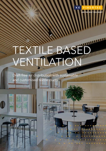
TEXTILE BASED VENTILATION Draft-free air distribution with sustainable and customised textile ducts