

FLC USER MANUAL

1 INTRODUCTION
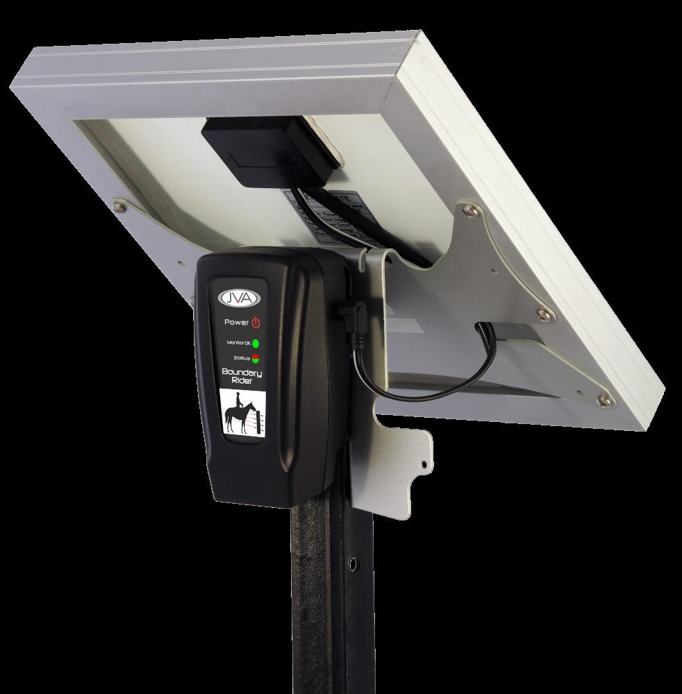
The JVA Boundary Rider and Base Station is an electric fence monitoring system that allows you to view your fence’s operation from anywhere in the world. It provides peace of mind that your property’s electric fence is working and it can also send an alert/notification to a mobile phone if a fault occurs. The JVA monitoring system adds more functionality to already popular JVA MB8/12/16 energizers, however it can also be used with most other branded energizers.
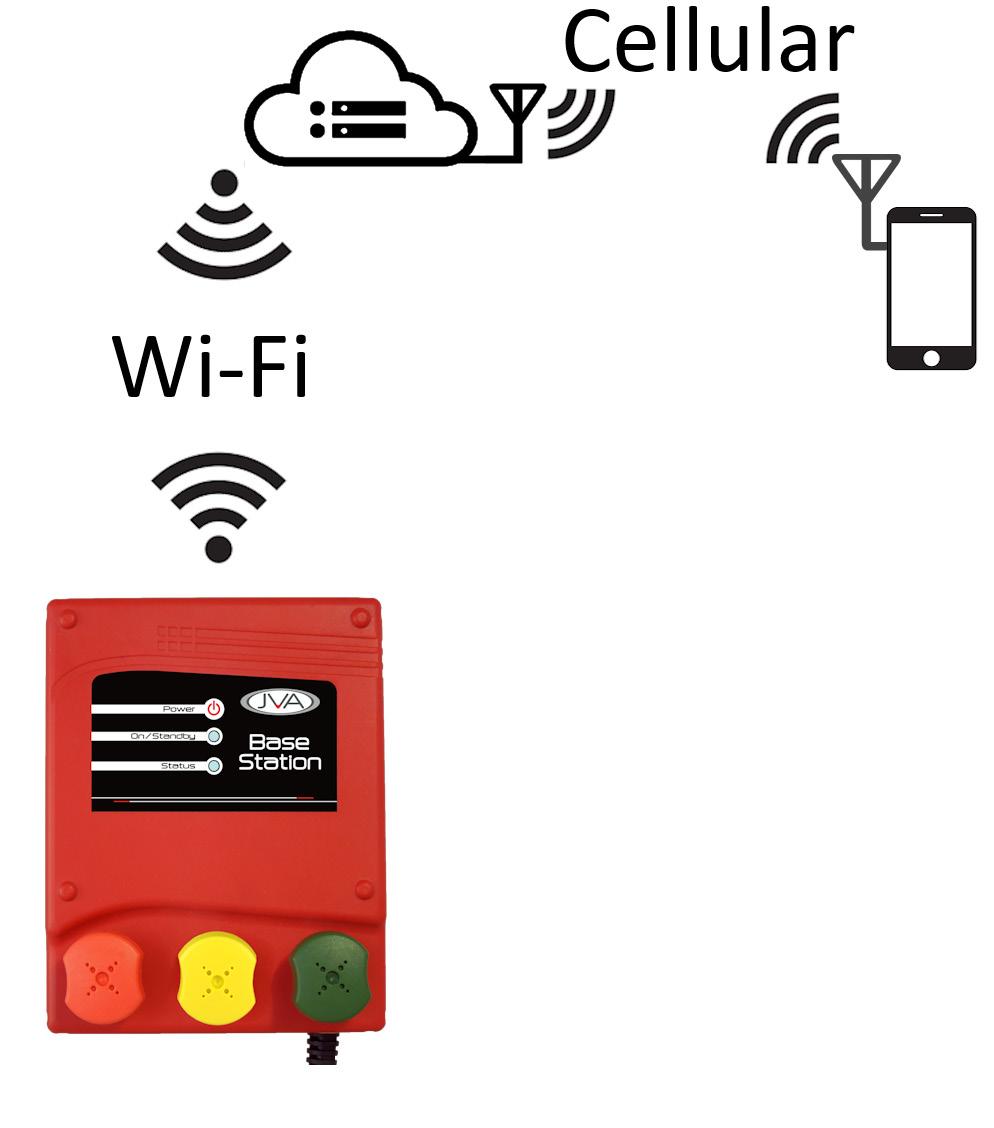
How does it work? Each Boundary Rider periodically sends the fence voltage information along the fence wires to the Base Station. The Base Station transfers this information to the JVA Cloud Servers over a Wi-Fi link.
1.1 FEATURES
The below table shows the features of FLC compatible devices.
• Electric fence voltage monitoring
• Communicates through the electric fence live wires
• Solar powered with integrated panel and bracket
• Star picket mounting bracket included
• Inbuilt Li-ion battery
• Compatible with all medium to high powered JVA energizers
• Auto power on / down
• Simple LED display
Introduction
2 JVA FENCE MONITORING SYSTEM
The Base Station is usually placed at the “Start” of the fence near the electric fence energizer to report on the quality of the entire fence. The voltage and current (amps) readings provides a good overall indication of the fence condition.
The Boundary Rider(s) should be placed at various points round the fence, or at fence ends to provide localized readings. Up to 10 Boundary Riders can be paired with one Base Station.
The Boundary Rider reports the fence voltage through the fence live wire using a “radio frequency” signal injected onto the fence live wires. The fence live wires carry the signal back to the Base Station. This transmission system uses the same tried and tested method as electric fence remote controls.
The Base Station receives these “radio” signals and forwards them to a User Interface via a Wi-Fi connection to the Internet (not included). This information can be accessed using the JVA IPEC App or Cloud Router App as long as the mobile phone has internet access. JVA recommends using an existing Wi-Fi Access point and Internet Plan if available; or a JVA Wi-Fi Anywhere® system that converts Wi-Fi to Cellular (4G) - signal strength permitting.
The fence communication system removes the need for a Wi-Fi or 4G router at each of the monitoring locations, reducing ongoing system costs and complexity.
A mobile phone, or tablet can also connect directly to the Base Station using Wi-Fi when close to the unit - within 25 meters. This connection is used to access the Virtual Keypad via an Internet Browser to access more detailed information about the monitoring system. The Virtual Keypad also allows configuration of the Base Station settings.

Fence Line Communication
3 MONITORING LAYOUTS
The simplest method of using Boundary Rider(s) to monitor your fence is to place one at each extremity of your farm. This is known as “End of Fence Monitoring”. By doing so you can check the voltage at the end and be assured that power is flowing all the way from the energizer to this point. I.e. your entire fence is fine.

An alternative is to use more Monitors to create “Sectors” within your fence system. The easiest way to think about this is to imagine a very long boundary fence. If you placed a Boundary Rider at regular intervals you will create a sector between each Boundary Rider. If Boundary Rider 2 says the fence is ok, but Boundary Rider 3 says it isn’t, then the fault is in sector 3.
Note: the Boundary Rider has been designed to operate at maximum distance of up to 6km away from the Base Station. This limitation can be ‘overcome’ by installing the Base Station in the middle/centre of the Boundary Riders.

End of fence Monitoring

Sector Monitoring
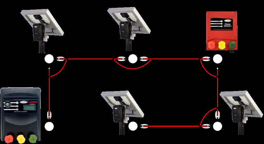
Centre of fence Monitoring
Monitoring Layouts
Parts
4 PARTS OF THE SYSTEM
THE BASE STATION

1. Power Button
2. On/Standby LED
3. Status LED
4. Energizer Terminal
5. Fence Terminal
6. Mains Cord
7. Negative Terminal
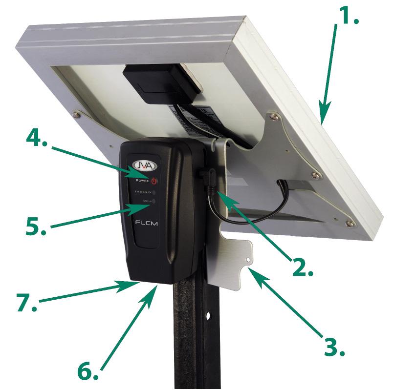
1. Solar Panel 2. Solar Panel lead and plug 3. Solar Bracket
Power Button
LED display 6. Earth terminal and lead 7. Fence terminal and lead
Parts of the system
4.3 FRONT DISPLAY
4.3.1 Base Station LEDs
On/Standby (GREEN)
OFF
Description
The Base Station is powered off ON The Base Station is Armed and the fence is On Flash The LED will flash off with each good pulse received from the Energizer. This shows that the fence is live.
Status (RED/GREEN)
OFF
Description
The Base Station powered down Green ON Normal operation, connected to Wi-Fi
1 Red Flash Not connected to Wi-Fi, needs to be configured
2 Red Flashes Attempting to connect to Wi-Fi
3 Red Flashes Connection to Wi-Fi established, will change to green soon
4 Red Flashes Connection to Wi-Fi failed, will try again
5 Red Flashes The FLCI has an incorrect password. Default the unit and enter password again
*Note: If the On/Standby LED is off but the status LED is on, the Base Station is disarmed, meaning the fence is off.
4.3.2 Base Station Power Button
4.3.3
Monitor
Boundary Rider
The Boundary Rider is powered off
Short Flash Battery is low
Long Flash Unit is on, Battery is charging ON Battery is fully charged
Status (RED/GREEN)
The Boundary Rider is powered off or No Fence Voltage in 10 seconds
Short Green Flash Fence Pulse seen over threshold
Short Red Flash Fence Pulse seen under threshold
Long Red ON No Fence Pulse seen for 2 seconds
Multiple Flashes Error code
4.3.4
serial number (factory use only)
Battery flat or failed - place the solar panel in the sun or replace the battery
General fault - return the product for service
Boundary Rider Power Button
Press the power button once to wake the Boundary Rider up.
Press and hold for 5 seconds to put the Boundary Rider to Sleep.
On/Sleep indicated by the Monitor OK LED
The Boundary Rider has two modes.
On: Green LED on or flashing
Sleep: No LED’s - will wake on button press, solar power or fence voltage
5 JVA USER INTERFACE OPTIONS
The Boundary Rider fence voltages can be checked using the Virtual Keypad (VKP) of the Base Station. This can only be accessed within 25m of the Base Station as this uses a direct connection between the Base Station and a smart phone/tablet. To check the fence condition from further afield, the Base Station will need to be connected to the Internet (Wi-Fi), and one of the Free JVA Electric Fence Apps download.
The JVA IPEC (IP Energizer Controller App) system is the recommended interface for remote monitoring. This can be downloaded from either the Google Play Store, or App Store. The simple interface is also used for the JVA MB8/MB12/MB16 Energizer information.

The JVA Cloud Router system has been geared towards the security sector and therefore contains more detail and features. This can be accessed from an Internet Browser, or from downloading the Cloud Router App from Google or Apple. This is ideal if you are already using a JVA Security Energizer and are comfortable using a slightly more complex interface.

JVA User Interface Options
6 INSTALLATION
6.1 CREATING A MONITORING SYSTEM
A JVA monitoring system only requires three devices, the Base Station, Boundary Rider(s) and an electric fence energizer.
1. Mount the Energizer and Base Station in suitable locations (See ‘Mounting’)
2. Wire the Energizer and Base Station together, and then to the fence
3. Temporarily connect the Boundary Rider to the fence. Ensure the Boundary Rider is not sitting on the ground.
*See “Wiring” for steps 2 & 3
4. Check the devices are working
*See “Unit Display”
5. Pair the Boundary Rider(s) to the Base Station
6. Connect the Base Station to the Internet
*See “VKP Setup” for steps 5 & 6
7. Download the User Interface of your choice
8. Add the Base Station to your IPEC or Cloud Routed Site
*See “UI Setup”
9. Press the Boundary Rider(s) button for 5 seconds to put it to sleep.
10. Move the Boundary Rider(s) to their intended position.
6.2 MOUNTING
6.2.1 Base Station
The Base Station should be installed near to the Energizer, close enough to allow a wired connection. Ensure a minimum separation of 50cm to reduce the electrical noise generated by the energizer interfering with the current (Amps) reading in the Base Station. The Base Station can be powered from either the Mains Power-pack, or from a 12Vdc battery system. Do not place the Base Station on the ground and ensure plenty of clearance between the fence terminals and any metal cabinet/enclosure.
6.2.2
Boundary Rider
After pairing the Boundary Rider(s) to the Base Station, mount each on a star picket or sturdy pole, up to 6km away from the Base Station, do not place it on the ground! Face the Solar Panel towards the equator.
Make a note of the Serial number of this Boundary Rider, you can use it to give it a location or name later. For example, serial number 123456 = Western fence end.
6.3 WIRING
6.3.1
Base Station
If an Energizer is not wired to the fence yet, go to step 3.
1. Turn the energizer off. Remove the power source from the energizer, and wait at least 10 seconds.
2. Disconnect the positive terminal of the energizer.
3. Using high voltage double insulated fencing cable
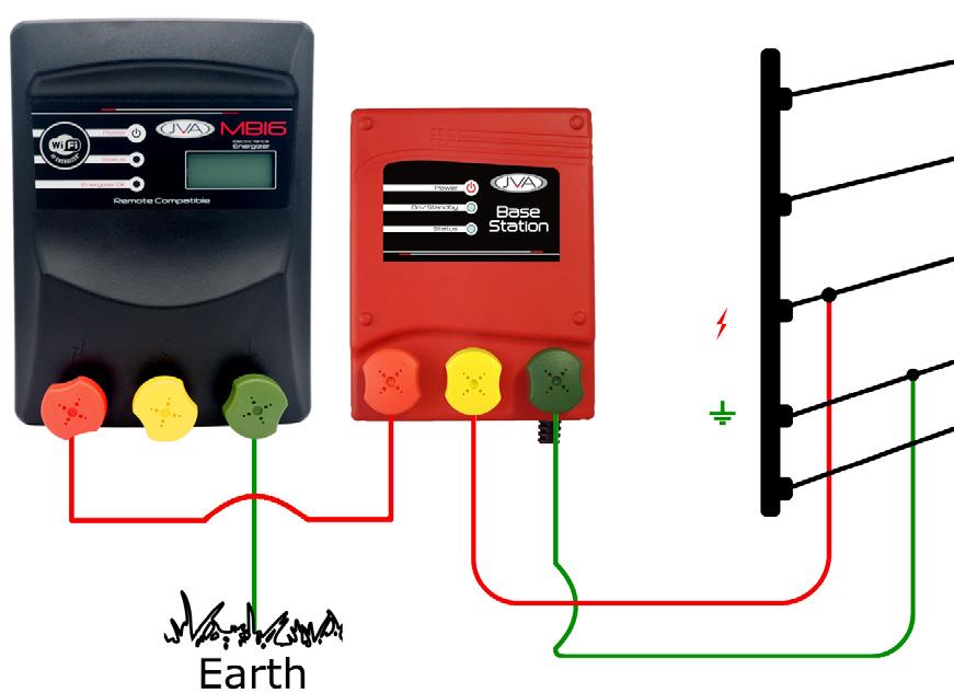
A. Wire the Base Station “Fence” terminal (Middle, Yellow terminal) to the electric fence live wire.
B. Wire the Base Station “Earth” terminal (Right, Green terminal) to a (non-live) grounded fence wire. *
C. Wire the Base Station “Energizer” terminal (Left, Red terminal) to the energizer’s ‘Fence’ Terminal (Red terminal).
*The Earth terminal of the Energizer should be creating a suitable earth connection (See energizer manual)
Installation
6.3.2 Boundary Rider
1. Turn the energizer off.
2. Wire the Boundary Rider “Fence” terminal to the electric fence live wire. If there are more than one live wire on the fence, connect them all together at this point.
3. Wire the Boundary Rider “Earth” terminal to a suitable Earth stake.
4. Plug the solar panel into the socket on the side of the Boundary Rider.
5. The Boundary Rider will automatically power up, if not press the switch on the front of the case.

6.4 VIRTUAL KEYPAD
6.4.1 Fast Pairing
Switch off the power to the Base Station, wait 10 seconds and then turn it back on. This starts the 4 hour ‘automatic pairing’ system.
Now for each Boundary Rider, press the button to send a signal to the Base Station, wait 5 seconds and press the button to send a signal again, wait another 5 seconds and press the button a third time. The Boundary Riders should now be paired to the Base Station. This should be confirmed in the Virtual Keypad.
6.4.2 Virtual Keypad Pairing
The JVA Virtual Keypad (VKP) is a browser based user interface used to view and manage the Base Station and Boundary Rider(s). To connect to the VKP ensure the Base Station is powered and you are within 25m of the unit. On your smart phone/tablet scan the QR code on the side of the Base Station. This will try to automatically connect to the Wi-Fi named “IPE-xxxxxx” where xxxxxx is the serial number of the Base Station. If this does not work, open your phone Wi-Fi settings and connect manually.

The phone browser should automatically open to the Base Station page. If it does not, you can manually access this by entering the address 192.168.4.1 into the browser.

Installation
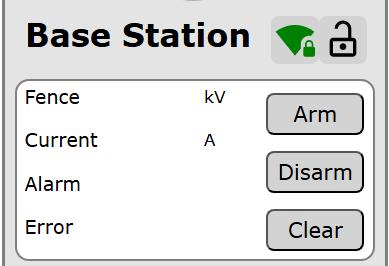
When the Base Station main page opens, click on the “Paired List” button at the bottom of the page.

Boundary Riders that have already been paired will be displayed in the list. To start pairing more Boundary Riders, click on the Start Pairing button. For each Boundary Rider, press its button twice with a 5 seconds pause between presses. The Paired List updates every 5 seconds and if the unit does not appear, press the Boundary Rider button again.

Press the Finish Pairing button when all Boundary Riders have been paired. Update the Name of each unit for better reference.
6.4.3 Connecting to the Internet
To connect your device to the internet, from the Base Station main page, click on the “Wi-Fi Settings” button.
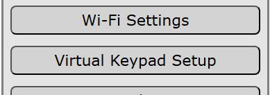
Select the App the Base Station will connect to, update the IPEC password if connecting to IPEC and then press the “Scan” button. After a few seconds the drop down list can be clicked to choose one of the available networks. Select the desired network and type the password. Press the “Connect” button. The Status LED on the Base Station will show the connection progress.
Status LED
Connection Progress
Red - 1 flash Ready for configuration
Red - 2 flash Wi-Fi settings entered
Red - 3 flash Connected to Wi-Fi Access Point
Green Connected to JVA Server
6.5 CHECK IT IS WORKING
In the Virtual Keypad of the Base Station, click on the “Boundary Riders” button on the main page. The details of each Boundary Rider will be displayed. Confirm the monitors are still sending information by looking at the Last Updated value. Each Boundary Rider sends a message every 3 minutes.

6.6
USER INTERFACE SETUP
You will need to choose one of the available options for User Interfaces. Download the App and setup your Site.
See www.jva-fence.com/agric/ipenergizer for information on setting up IPEC
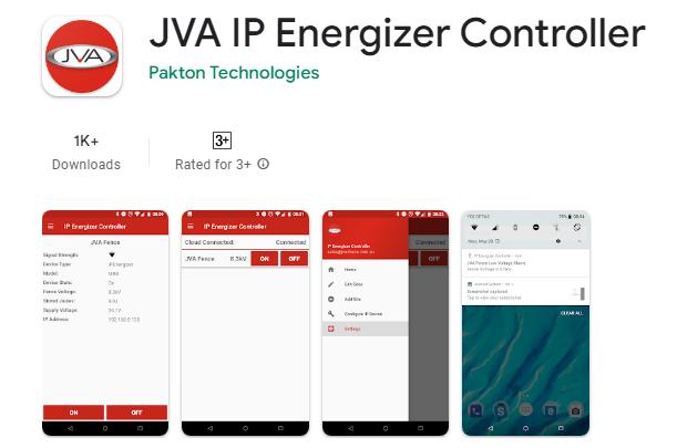
See www.jva-fence.com/CloudRouterGuide for information on setting up Cloud Router.

7 OPERATION
Use the JVA IPEC or Cloud Router to check your fence on a regular basis. You will get to know what the normal running voltages are at the various points on your fence.
If there is a fault on your fence, for example the voltage at a Boundary Rider falls below the set threshold, you should receive a notification. This is dependent on the setup of your chosen User Interface.
If the fence is damaged to the extent that FLC signals cannot get back to the Base Station the system will generate a coms fail alarm. Again you will receive a notification.
7.1 FAULT FINDING
1. Coms Fail Alarm: The Base Station does not see the Boundary Rider. This means that the RF signals from the FLC are not making it back to the Base Station.
a. There could be a break or short in the live wire somewhere between the Base Station and the Boundary Rider. Check your fence for faults
b. Try moving the Boundary Rider closer to the Base Station
2. If the Boundary Rider flashes a low / bad battery code
a. Make sure the solar panel is not shaded. It should get full sun from at least 10am to 4pm each day.
7.2 LIMITATIONS
The Boundary Rider (PTE0352) will only read electric fence voltage for positive pulsed energizers. All JVA Agric and Security energizers produce a positive pulse. Some other brands use a negative pulse.
There is no galvanic isolation from the Fence Ground to the solar panel power input. This means that the solar panel and bracket become live if the Earth connection is lost or is inadequate.
The Boundary Rider will last 6 days without direct sunlight, and will be fully operational during that period.

