A BLOG BY JUNRONG WANG ABOUT GITHUB LINK INTRO-TO-IOT_CUBOCTAHEDRON-POMODORO
CUBOCTAHEDRON POMODORO RETHINKING THE GEOMETRY OF FOCUS
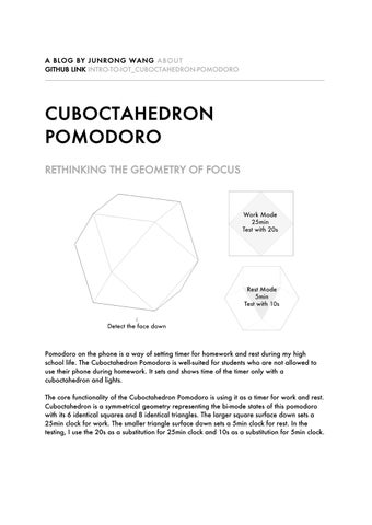
Pomodoro on the phone is a way of setting timer for homework and rest during my high school life. The Cuboctahedron Pomodoro is well-suited for students who are not allowed to use their phone during homework. It sets and shows time of the timer only with a cuboctahedron and lights. The core functionality of the Cuboctahedron Pomodoro is using it as a timer for work and rest. Cuboctahedron is a symmetrical geometry representing the bi-mode states of this pomodoro with its 6 identical squares and 8 identical triangles. The larger square surface down sets a 25min clock for work. The smaller triangle surface down sets a 5min clock for rest. In the testing, I use the 20s as a substitution for 25min clock and 10s as a substitution for 5min clock.
The circuit consists of an Arduino MKR Wi-Fi 1010 microcontroller1,2, an MPU-6050 module for motion sensing (combining a 3-axis gyroscope and a 3-axis accelerometer)3, a green LED push button (DFR0785-G)4, and a 3.7V Polymer Lithium-Ion (LiPo) battery for power5.
INSTRUCTION FOR USERS Plug in the data cable and connect the Arduino board to a computer. Upload the script to Arduino through data cable so it would connect to the WIFI and MQTT. If the battery power is enough, unplug the cable and close the lid to use it. Otherwise, charge it for 30 - 60min. Or just use it with a cable plugged in to test. Press the button to start detection (chaser runs on the lights) or press again to stop detection. Place the object with a square face down to start a work session. Or place it with a triangle face down to start a rest session. Hold a face steady for 10s (demo mode) to confirm; LEDs and the website visualize the state. Production timings: 25min work, 5 min rest; demo timings: 20s/10s.
EFFECTS WAITING FOR DETECTION
The chaser blocks traverse through the 72 pixels repeatedly.
Arduino (n.d.) Arduino MKR WiFi 1010 (ABX00023) datasheet. Available at: https://docs.arduino.cc/resources/datasheets/ABX00023-datasheet.pdf (Accessed: 6 November 2025). 2 Arduino (n.d.) MKR WiFi 1010 pinout (latest). Available at: https://content.arduino.cc/assets/PinoutMKRwifi1010_latest.pdf (Accessed: 6 November 2025). 3 InvenSense (n.d.) MPU-6000 and MPU-6050 Register Map and Descriptions. Rev. 4.0. Available at: https://cdn.sparkfun.com/datasheets/Sensors/Accelerometers/RM-MPU-6000A.pdf (Accessed: 5 November 2025). 4 DFRobot (n.d.) LED Button (SKU: DFR0785). Available at: https://wiki.dfrobot.com/_SKU_DFR0785_LED_Button (Accessed: 6 November 2025). 5 Li-Polymer Battery (n.d.) 3.7V Standard Li-Polymer Battery 6000mAh. Available at: https://li-polymerbattery.com/3-7v-standard-li-polymer-battery-6000mah+/ (Accessed: 6 November 2025). 1
DETECTION STOPPED
No pixel is lightened.
WORK MODE (SQUARE FACE DOWN)
The gradient fills the pixels row by row gradually. A row of pink pixels traverses from top to bottom repeatedly.
REST MODE (TRIANGLE FACE DOWN)
The veered gradient blink through the pixels from left to right repeatedly. The greyscale monochrome lighten pixels are filled by a gradient from left to right column by column.
CUBOCTAHEDRON AS INTERNET OF THINGS SCHEMATIC DIAGRAM
CORE BUILDING BLOCKS Things (Devices/Sensors/Actuators)
MKR Wi-Fi 1010, MPU-6050, button, LiPo battery
Connectivity
Wi-Fi → TCP 1884 →MQTT →WebSockets
Messaging / Broker
mqtt.cetools.org:1884 (the MQTT broker)
Applications (Dashboards/Services/Logic)
web app rendering frames + sending commands
Security/Identity
MQTT Client ID
ACTORS Device/Edge Developer
Maker, Arduino code
Broker Operator
Professor
Application Developer
Maker, professor
End User
viewer/controller
builds sensing/logic and MQTT client behaviour runs and secures the MQTT broker builds the browser UI, subscribes/publishes topics uses the web UI to view LEDs and send commands
EDGE COMPUTING, CLIENT, AND CLOUD SERVER
MKR + MPU-6050 is an edge device that runs inference locally and then, as an MQTT client, publishes its results and listens for simple commands via the cloud, MQTT broker. The website and the Vespera lights subscribe to the MQTT Broker Cloud as Clients. MKR WIFI 1010 (WITH MPU-6050) → EDGE DEVICE/MQTT CLIENT
The MKR WiFi 1010 does the heavy lifting on-device: read accel, normalize, smooth, detect face, generate LED frames. It then publishes frames + status JSON, subscribes to user/brightness topics. This is the edge computing part. It is a MQTT client because it does the things an MQTT client does, initiating a connection to a MQTT broker. These include using PubSubClient, publishing messages to topics, subscribing to topics and handles incoming messages, and maintaining the session and reconnects. The benefits of being a client at the edge includes NAT/firewall friendly, decoupled, lightweight, and resilience. NAT/firewall friendly means there is only outbound connection to the broker, no inbound ports on the device. Decoupled means the device does not need to know who is listening. Lightweight means it does not need to run a broker which is perfect for micro controllers. Resilience means simple reconnect logic. Retained messages are stored by the broker as the latest values for a topic even if the Wifi is unconnected. In this case, it retains the user and brightness messages. While reconnected, the edge device will automatically get the last values of user and brightness if they are not reassigned. MQTT.CETOOLS.ORG:1884 → MQTT BROKER (CLOUD)
The MQTT is the cloud, which is the central hub that routes messages between clients. In the code: mqtt_base_topic = student/CASA0014/luminaire publishes to .../<user> and .../cmd, subscribes to .../user and .../brightness. COMPUTER (IDE AND WEBSITE) → MQTT CLIENT (VIEWER/CONTROLLER/CLIENT)
The browser app subscribes to student/CASA0014/luminaire/<user> to render the virtual Luminaire, and can publish commands in Arduino IDE(e.g., brightness/user). VESPERA LIGHTS (CLIENT)
The Vespera works as a web client. It subscribes to the frame topic.
CUBOCTAHEDRON POMODORO AND IoT’s IMPACT ON THE BUILT ENVIRONMENT The cuboctahedron pomodoro shows the combination of design and IoT, using shape as the controller in IoT to replace a switch. The shape detection in this prototype is a pose detection and analyzation of the sensor data using linear algebra and stereo-geometry. It can be applied to installations in built environment, for example, a drivable house. The direction of the drivable house determines the window directions, affecting the light shed into the house. Therefore, the similar pose detection logic can be used to control the kinetic curtains on the windows. The same logic can also be used to deal with wind. These are critical in extreme climate and weather. Normally these kinetic windows in built environment are using temperature sensors. Adding a pose detection combined with local climate data can make the detection more accurate. If the pose detection and temperature detection yields the same or similar results, it increases the confidence measure.
MERITS It connects physical interaction, edge computing, event-driven networks and visualization into a closed loop. Edge-side filtering + hysteresis + dwell time can eliminate "false triggering" at the device end and reduce the noise of uplink data (the value of edge computing). Robustness. ROBUSTNESS Unit-vector normalization + zero-guard
I compute n2 and bail if it’s ≈0, then normalize → prevents NaNs and ensures stable dot products. If I don’t normalize the accelerometer vector, the direction test gets contaminated by magnitude, which breaks thresholds, hysteresis, and dwell logic. Because the thresholds are set assuming that the n2 is normalized LPF + re-normalize
Exponential smoothing (LPF_ALPHA) damps jitter; re-normalizing keeps math stable. Hysteresis (ENTER_TH/EXIT_TH)
It avoids flicker when the score hovers near the threshold. 10-second dwell confirmation (DWELL_MS)
It suppresses false triggers from bumps. Re-arm dip (REARM_DROP_MS)
After confirming a face, don’t consider any new face until the current face’s score has dipped below a lower threshold (EXIT_TH) for at least REARM_DROP_MS milliseconds. Last-confirmed suppression
This is to ignore the same face immediately after confirming it to prevent repeats.
DEMERITS The function of the pomodoro needs to be explained to the user. The prototype needs to be improved even after adding a button to enable/disable detection and a LIPO battery for unplugged use. The LIPO battery power cannot be turned off by the current push button. Possible solution 1: Connect a toggle switch or a push-button switch with self-locking function in series between the positive terminal of the battery and the positive terminal of the CPU board1. Possible solution 2: Use a P-channel MOSFET as a high-side switch on the power supply → MKR WiFi 1010 line (for example, 5V → VIN). The gate is pulled up to the power supply, so the MOSFET is off by default. Pressing a non-self-locking button momentarily pulls the gate to a low level → the MOSFET conducts → the board powers on. As soon as the board powers on, the CPU immediately uses an I/O pin to keep the gate pulled low. This way, even if the button is released, the MOSFET will remain on - this is self-holding. To turn off the device, the CPU sets this I/O pin to high impedance ors high level, allowing the gate to be pulled up again, the MOSFET turns off, and the entire board powers down6.
Mosaic Industries (n.d.) Push Button ON–OFF Soft Latch Circuits, Battery Powered Applications. Mosaic Industries. Available at: https://www.mosaic-industries.com/embedded-systems/microcontrollerprojects/electronic-circuits/push-button-switch-turn-on/latching-toggle-power-switch (Accessed: 6 November 2025). 6
MESSAGE TO MQTT 1)72-LED frame bytes (binary) à
Topic: student/CASA0014/luminaire/ (built into mqtt_data_topic as "%s/%d" % (mqtt_base_topic, LUMINAIRE_USER))
à
Payload: raw binary buffer frameBuf of length 216 bytes (= 72 LEDs × 3 bytes per LED). Format per LED: GRB order (that’s how NeoPixel expects it): [G0, R0, B0, G1, R1, B1, ... G71, R71, B71]
When sent, every time call publishFrame() from effect loops, it shows as a blob of bytes that can be toggled to hex7. 2)JSON “telemetry/commands” for status/timer
These are the two snprintf(...) payloads published to the MQTT: à
Timer/transition message (called in updateEffects() when switching modes): Example payload: {"device":"MKR1010_Cubo_FaceEffects","cmd":"timer","palette":"row_temporal_grad" ,"seconds":20,"face":"+X"} {"device":"MKR1010_Cubo_FaceEffects","cmd":"timer","palette":"grad_chaser","secon ds":0,"face":"square"}
à
State/lock message (sent on 10-second confirmation): {"device":"MKR1010_Cubo_FaceEffects","cmd":"state","face":"+X","type":"square","sc ore":0.913,"valid":true,"locked":true}
3)Control inputs to listen for: /user and /brightness (plain numbers)
Wilson, D. (2025) Chrono Lumina. GitHub repository. Available at: https://github.com/ucl-casace/casa0014(Accessed: 5 November 2025). 7
DESIGN
Form follows function. - Louis Sullivan The design follows the design principle that form follows functions in architecture8. This geometry works as an abstract switch with correspondence from shape to time. The larger surface with 4 edges means a longer time of working mode. The smaller surface with 3 edges means a shorter time of working mode.
The first demo: This demo consists of Arduino MKR Wi-Fi 1010 microcontroller, and an MPU-6050 module for motion sensing (combining a 3-axis gyroscope and a 3-axis accelerometer). There is no button and battery, so it must be connected to computer with cable while using. The second demo: In this demo, I added a green LED push button (DFR0785-G), and a 3.7V Polymer Lithium-Ion (LiPo) battery for power. Therefore, after uploading the script to MKR Wi-Fi 1010 microcontroller, it can still be used after unplugging. A button is added to enable or disable detection.
Sullivan, L.H. (1896) ‘The Tall Office Building Artistically Considered’, Lippincott’s Monthly Magazine, 57 (March), pp. 403–409. 8
ALGORITHM FOR FACE DETECTION USING ACCELERATION FROM IMU Instead of computing the angle on 3 axes, I calculate the angle between gravity vector of square faces and triangle faces predefined and measured acceleration vector from IMU (MPU 6050) over I²C two-wire serial bus3.
THE SENSOR DATA PREPROCESSING The sensor data preprocessing includes normalization, smoothing, and renormalization. Let 𝑔 = #𝑔! , 𝑔" , 𝑔# % be the raw vector, which is the acceleration data read from the sensor. It is composed of data on X, Y, and Z axes. Compute squared norm: 𝑛$ = |𝑔|$ = 𝑔!$ + 𝑔"$ + 𝑔#$ Guard against near-zero vector: if 𝑛$ < 𝜀 (𝜀 = 10%& ), skip/return.
NORMALIZATION The normalization of to make it easy for calculating dot product to compute the angle. 𝑔 !=
𝑔
"|𝑔|"
=
1
√𝑛2
%𝑔𝑥 , 𝑔𝑦 , 𝑔𝑧 &
Update the value of 𝑔0 = #𝑔 1, 𝑔" , 𝑔 1%: ! 1 # 𝑔'𝑥 = 𝑔𝑥 × (𝑔2𝑥 + 𝑔2𝑦 + 𝑔2𝑧 𝑔'𝑦 = 𝑔𝑦 × (𝑔2𝑥 + 𝑔2𝑦 + 𝑔2𝑧 𝑔'𝑧 = 𝑔𝑧 × (𝑔2𝑥 + 𝑔2𝑦 + 𝑔2𝑧 So"|𝑔 ! |" = 1, 𝑔! is the unit gravity direction vector9.
Shanghai Jiao Tong University, Faculty of Mathematics (n.d.) Linear Algebra. Shanghai: Shanghai Jiao Tong University Press. 9
SMOOTHING The ‘Low-pass’ part is doing smoothing: It removes high-frequency jitter/noise and short bumps from the accelerometer, so the “which face is down” logic doesn’t flicker. LPF_ALPHA (α) is the smoothing factor for the exponential moving average(EMA) on the gravity vector. f(𝑔! ) = (1.0 − α) × f(𝑔! ) + α × 𝑔! f#𝑔" % = (1.0 − α) × f#𝑔" % + α × 𝑔" f(𝑔# ) = (1.0 − α) × f(𝑔# ) + α × 𝑔# It employs the function: New = (1-LPF_ALPHA)·Old + LPF_ALPHA·Current10. Smaller values of LPF_ALPHA result in greater smoothing, leading to a slower response but reduced jitter. Larger values of LPF_ALPHA yield a faster response, albeit at the cost of allowing more jitter to pass through.
RENORMALIZATION Re-normalize the 𝑔⃗ to unit length. 2
2
2
𝑚2 = f)𝑔𝑥 * + f %𝑔𝑦 & + f)𝑔𝑧 * f(𝑔! ) = f(𝑔! ) × 9𝑚$ f#𝑔" % = f#𝑔" % × 9𝑚$ f(𝑔# ) = f(𝑔# ) × 9𝑚$
+𝑔⃗ = -f)𝑔𝑥 *,
f %𝑔𝑦 & ,
f)𝑔𝑧 *.
THE PREDEFINED VECTORS OF SQUARES AND TRIANGLES Defining the vectors for squares and triangles. 𝑁6 = {(1,0,0), (−1,0,0), (0,1,0), (0, −1,0), (0,0,1), (0,0, −1)} 1
1
1
1
1
1
1
1
1
1
1
1
⎧- , , . , - , , − . , - , − , . , - , − , − . ,⎫ √3 √3 √3 √3 √3 √3 √3 √3 √3 √3 √3 √3 ⎪ ⎪ ⎪ ⎪ 1 1 1 1 1 1 1 1 1 -− , , . , -− , , − . , -− , − , . , 𝑁8 = √3 √3 √3 √3 √3 √3 √3 √3 √3 ⎨ ⎬ 1 1 1 ⎪ ⎪ ⎪ ⎪ -− , − , − . ⎩ ⎭ √3 √3 √3
NIST/SEMATECH (n.d.) e-Handbook of Statistical Methods. Available at: https://www.itl.nist.gov/div898/handbook/(Accessed: 5 November 2025). 10
ANGLE CALCULATION BETWEEN THE CURRENT AND EXPECTED STATES The general rule is:
+𝑎⃗ ∙ 𝑏+⃗ = "|𝑎|""|𝑏|"𝑐𝑜𝑠𝜃 E⃗ are unit vectors: So if 𝑔⃗ and 𝑁 E⃗ ∙ 𝑔⃗ = −𝑐𝑜𝑠𝜃 𝑠𝑐𝑜𝑟𝑒 = −𝑁 E⃗ ∙ 𝑔⃗) 𝜃 = 𝑎𝑟𝑐𝑐𝑜𝑠(𝑁 E⃗ 4. 𝜃 is the angle between the normal 𝑔⃗ and surface normal 𝑁 E⃗ points opposite 𝑔⃗ , so 𝜃 ≈ 𝜋 and 𝑐𝑜𝑠𝜃 ≈ −1. When the surface faces are down, 𝑁 E⃗ ∙ 𝑔⃗ is the largest(≈ 1) when the face is down, near 0 when orthogonal, and Therefore, −𝑁 negative when it is up. E⃗ belongs to collection 𝑁& , it is square. If the 𝑁 E⃗ belongs to collection 𝑁- , it is triangle. If the 𝑁
THE 2 ANGLE THRESHOLDS TO DETERMINE THE STATE The tolerance angle is set by 2 thresholds, ENTER_TH and EXIT_TH11, 12. The ENTER_TH is to set angle tolerance to lock a surface. The EXIT_TH is to set angle threshold to exit the current surface state. So the condition for exiting the state is more tolerant for the condition for entering the state. I record the parameters of the current best candidate face in variable bestIdx, bestIsSquare, and bestScore. The bestScore is the dot product. The bestIsSquare holds what you are locked onto, square or triangle. The idx==-1 means ‘not tracking anything yet’.
So if there is no face locked, compare the bestScore to ENTER_TH, if it is larger than ENTER_TH, substitute the parameters of best surface to those of this surface. It means it does not start tracking until the best candidate is confident enough (>ENTER_TH, 𝜃 > arccos (−0.80) ≈ 143.13°) and 𝜃 < 180°. The hysteresis on the angle aspect is achieved by comparing the score to EXIT_TH. The score < EXIT_TH means the 𝜃 < arccos (−0.72) ≈ 136.1°. It exits when this condition is met.
Schmitt, O.H. (1938) ‘A Thermionic Trigger’, Journal of Scientific Instruments, 15(1), pp. 24–26. doi:10.1088/0950-7671/15/1/305. 12 Wikipedia (n.d.) ‘Schmitt trigger’. Available at: https://en.wikipedia.org/wiki/Schmitt_trigger (Accessed: 5 November 2025). 11
REFERENCES 1. Arduino (n.d.) Arduino MKR WiFi 1010 (ABX00023) datasheet. Available at: https://docs.arduino.cc/resources/datasheets/ABX00023datasheet.pdf (Accessed: 6 November 2025). 2. Arduino (n.d.) MKR WiFi 1010 pinout (latest). Available at: https://content.arduino.cc/assets/Pinout-MKRwifi1010_latest.pdf (Accessed: 6 November 2025). 3. InvenSense (n.d.) MPU-6000 and MPU-6050 Register Map and Descriptions. Rev. 4.0. Available at: https://cdn.sparkfun.com/datasheets/Sensors/Accelerometers/RM -MPU-6000A.pdf (Accessed: 5 November 2025). 4. DFRobot (n.d.) LED Button (SKU: DFR0785). Available at: https://wiki.dfrobot.com/_SKU_DFR0785_LED_Button (Accessed: 6 November 2025). 5. Li-Polymer Battery (n.d.) 3.7V Standard Li-Polymer Battery 6000mAh. Available at: https://li-polymer-battery.com/3-7v-standard-li-polymerbattery-6000mah+/ (Accessed: 6 November 2025). 6. Mosaic Industries (n.d.) Push Button ON–OFF Soft Latch Circuits, Battery Powered Applications. Mosaic Industries. Available at: https://www.mosaic-industries.com/embeddedsystems/microcontroller-projects/electronic-circuits/push-button-switchturn-on/latching-toggle-power-switch (Accessed: 6 November 2025). 7. Wilson, D. (2025) Chrono Lumina. GitHub repository. Available at: https://github.com/ucl-casa-ce/casa0014(Accessed: 5 November 2025). 8. Sullivan, L.H. (1896) ‘The Tall Office Building Artistically Considered’, Lippincott’s Monthly Magazine, 57 (March), pp. 403– 409. 9. Shanghai Jiao Tong University, Faculty of Mathematics (n.d.) Linear Algebra. Shanghai: Shanghai Jiao Tong University Press. 10. NIST/SEMATECH (n.d.) e-Handbook of Statistical Methods. Available at: https://www.itl.nist.gov/div898/handbook/(Accessed: 5 November 2025). 11. Schmitt, O.H. (1938) ‘A Thermionic Trigger’, Journal of Scientific Instruments, 15(1), pp. 24–26. doi:10.1088/0950-7671/15/1/305. 12. Wikipedia (n.d.) ‘Schmitt trigger’. Available at: https://en.wikipedia.org/wiki/Schmitt_trigger (Accessed: 5 November 2025).