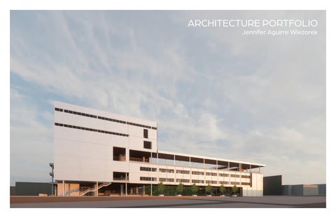
Thank you for taking the time to review my work! The projects included in this portfolio were selected to represent my comprehensive approach to architectural design. I welcome the opportunity to connect and can be reached at: jenniferaguirregarcia@gmail.com
archive and reading room building for Columbia University at the Manhattanville Campus.
University of Texas at Arlington School of Architeture
Bijan Youssefzadeh
TRININTY HALL
CAPPA SOUTH
MUSIC HALL
FINE ARTS
CAPPA NORTH
NANOTECH BUILDING
CAPPA
UNIVERSITY VILLAGE
MAVERICK ACTIVITY CENTER
PROPOSED CAPPA
W NEDDERMAN DR.
GREEK ROW
1/16"=1'-0"
1"=40'-0"
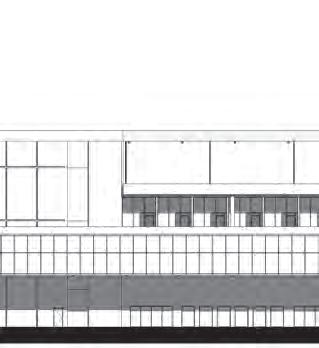
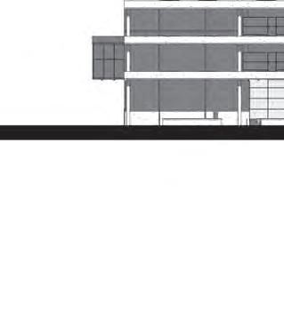
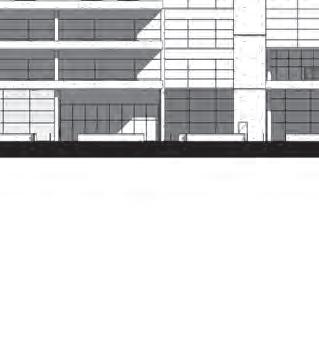
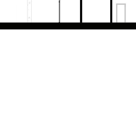
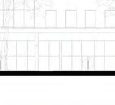
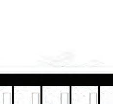
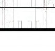
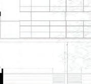
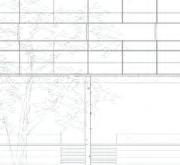
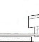
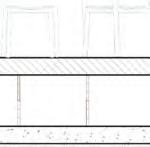
SOUTH ELEVATION
1"=40'-0"
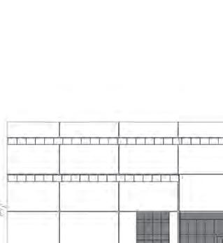
EAST ELEVATION
1"=40'-0"
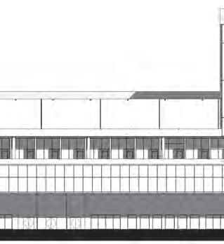
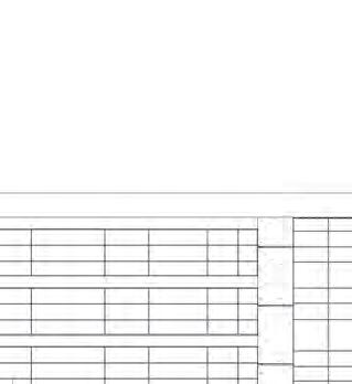
1"=40'-0" NORTH ELEVATION
WEST ELEVATION
1/16"=1'-0"
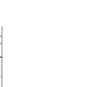
A-A
SECTION
SECTION
1/16"=1'-0"
SECTION C-C 1/16"=1'-0"
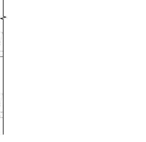
SECTION C-C
1/16"=1'-0"
SECTION D-D
1/16"=1'-0"
LEVEL 02 MECHANICAL
LEVEL 01 MECHANICAL
LEVEL 01 LIGHTING PLAN 1"=40'-0"
STRUCTURE
ISOMETRIC
EXPLODED
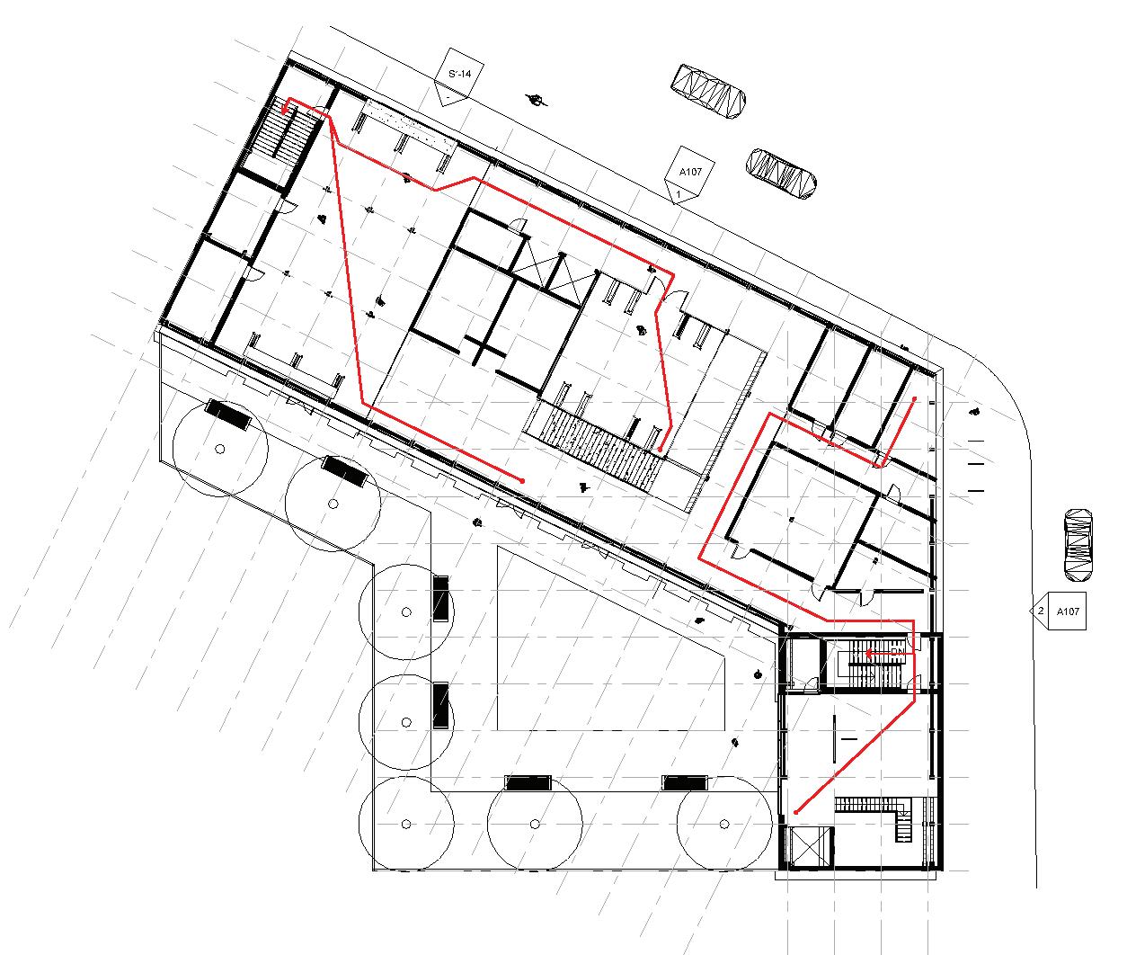
LEVEL 06 EGRESS
LEVEL 04 EGRESS
LEVEL 02 EGRESS
LEVEL 01 EGRESS
GRANT ARCHIVE
PROJECT 02
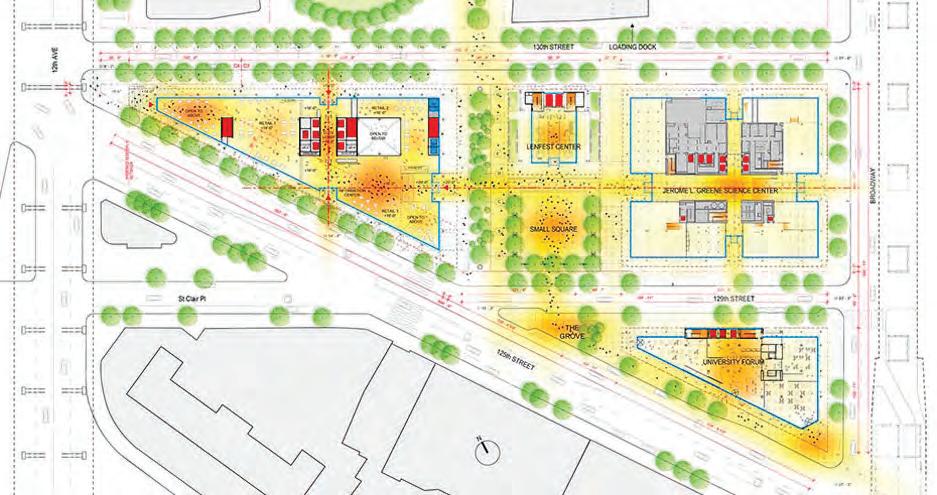
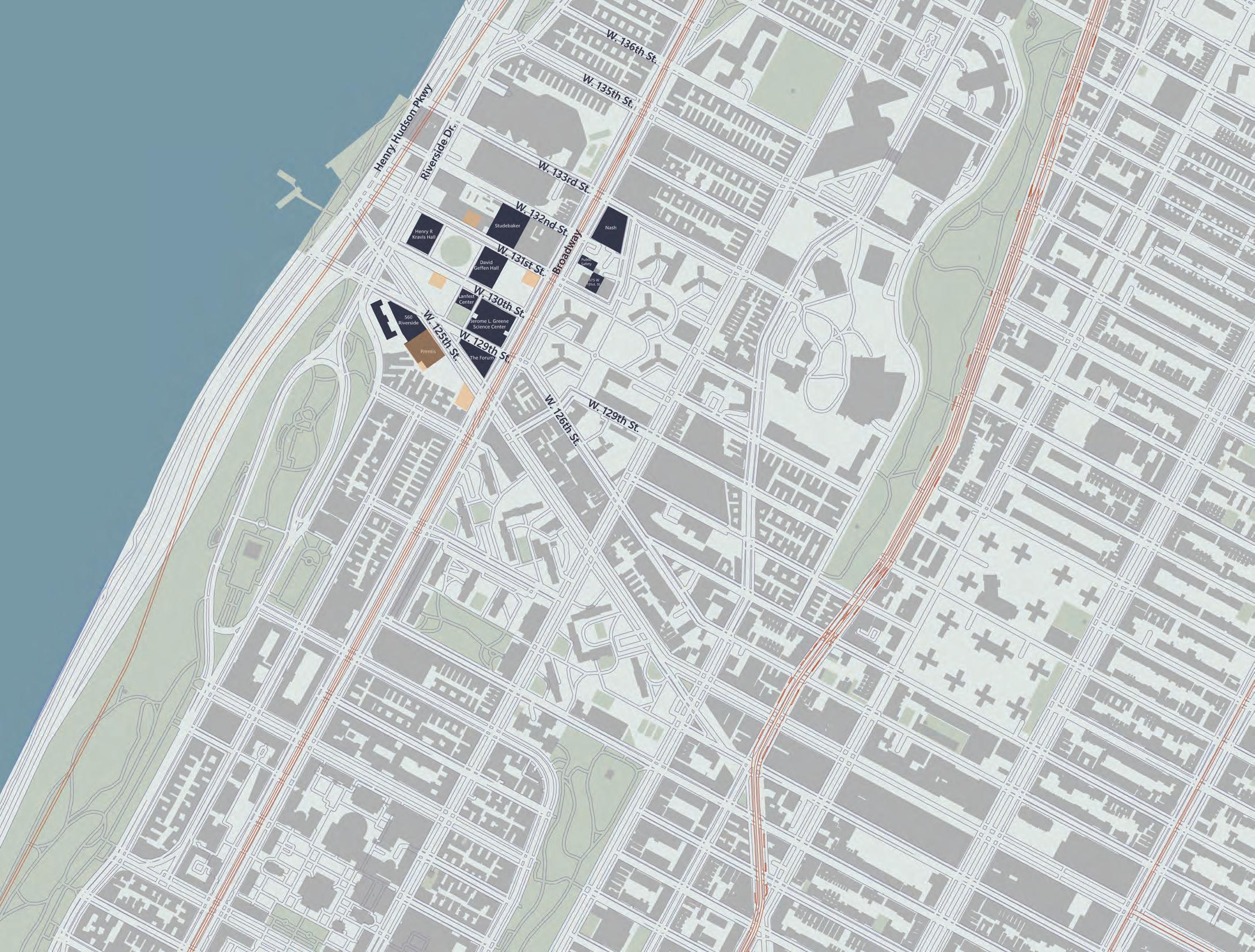
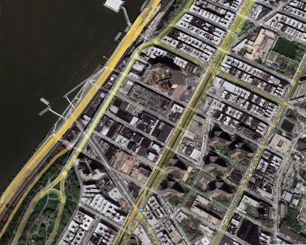
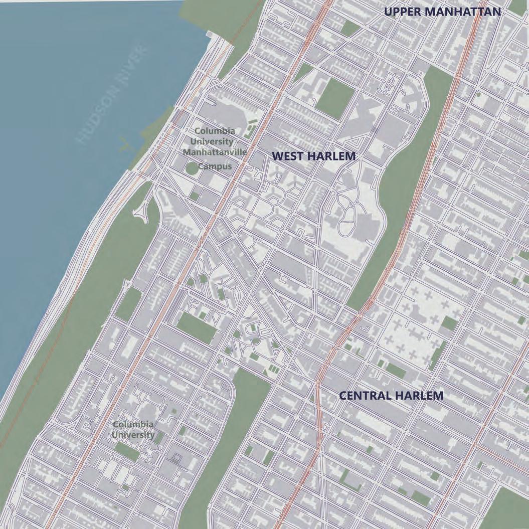
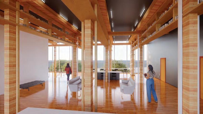
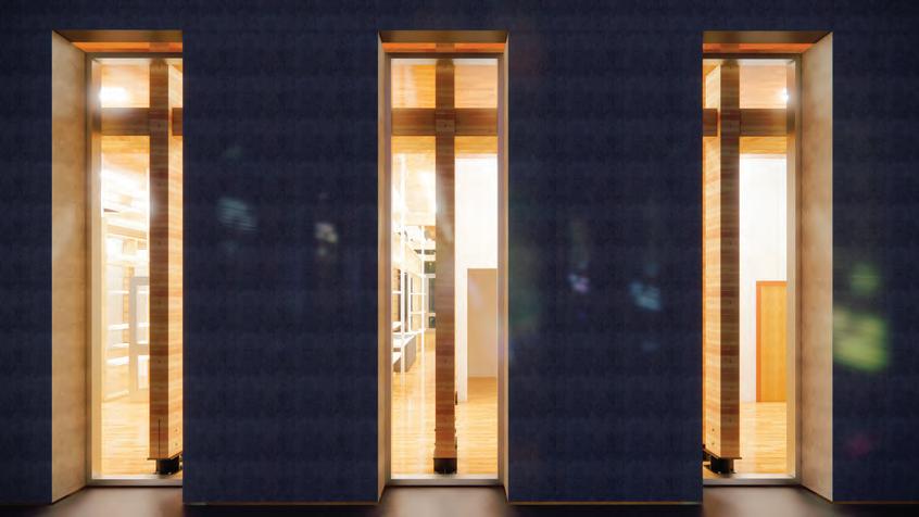
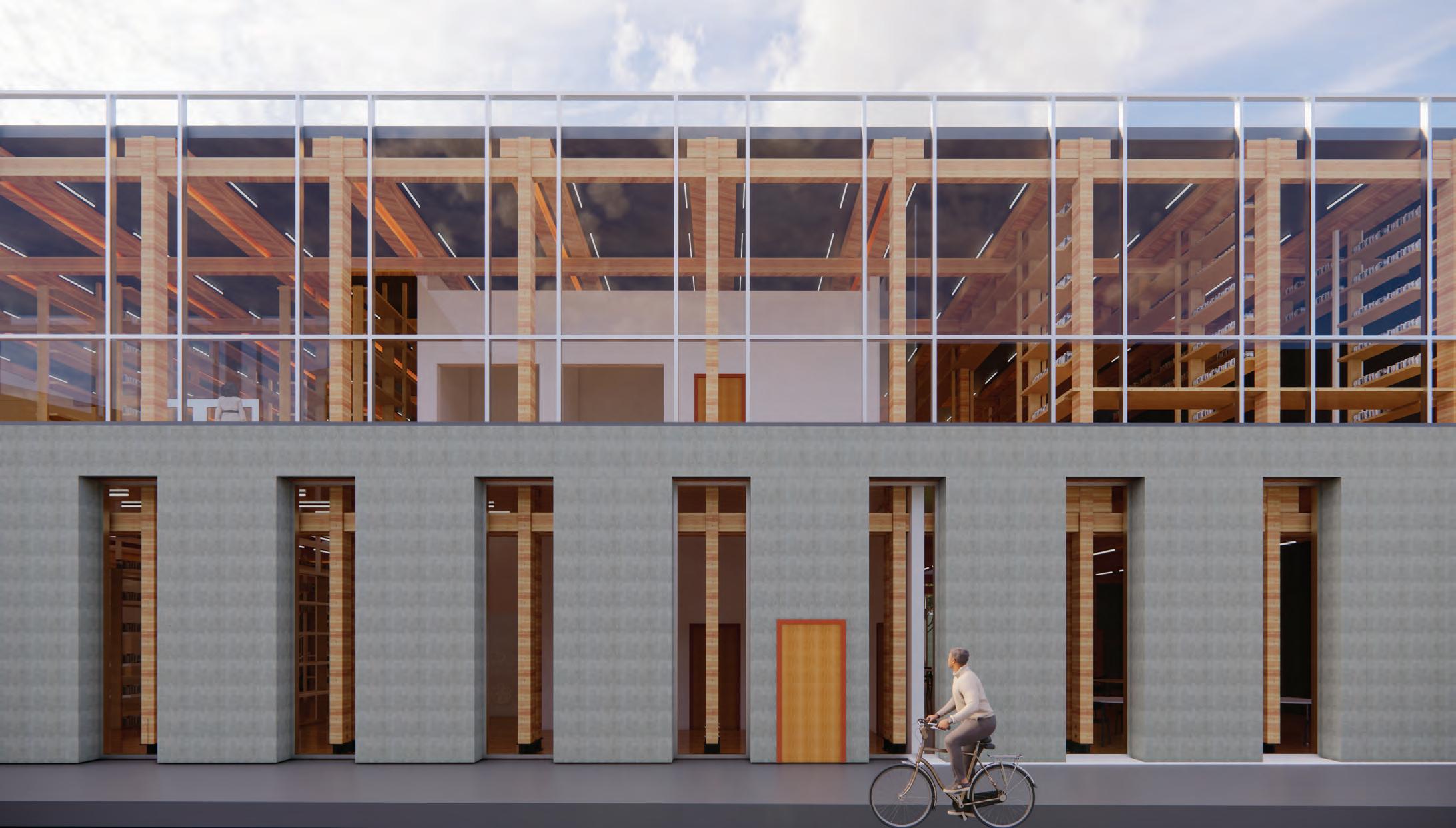
The Grant Archive building is an archive and reading room building for Columbia University at the Manhattanville Campus. The location was chosen on the corner of Broadway and W. 125th Street, to create a new beginning to the edge of campus. Its footprint is gained through the circulation created through the Forum Building, Jerome L. Greene Science Center, and the Lenfest Center. The campus holds Renzo Piano buildings that are concrete-heavy; therefore, the archive building holds a concrete feel on the outside to fit in with the campus while keeping its character inside through its timber structure. As you walk along the sidewalk, you’ll see thin window openings to give you a sneak peek of what’s inside.
ARCH 5671 SP 2023
Charles Macbride
Grant Archive - Table of Contents
Precedent Studies
A-01 Precedent Study 01 Statement
A-02 Precedent Study 01 Thumbnails
A-03 Precedent Study 02 Statement
A-04 Precedent Study 02 Thumbnails
Programming Research, Analysis & Documentation
B-01 Programming Statement
B-02 Columbia University Mission & Goals
B-03 Manhattanville Master Plan Program Analysis
B-04 Building Program Analysis & Narrative
B-05 Building Program & Tabulation
Site Research, Analysis & Documentation
C-01 Site Design Statement
C-02 Individual Site Research
C-03 Regional Map
C-04 Formal Analysis Drawing
C-05 Site Circulation Diagrams
C-06 Topography & National Features Diagram
C-07 Historical Site Analysis
C-08 Site Use Information
C-09 Planning/Zoning/Municipal Analysis
C-10 Site Opportunities Diagram
C-11 Additional Site Analysis & Drawings
Tectonics / Concept Design / Design Charrette
D-01 Tectonic Path Statement
D-02 Charrette 01: FOURS Models & Statement
D-03 Charrette 02: FIVES Models & Statement
D-04 Charrette 03: SIXES Models & Statement
D-05 Charrette 04: Prototype Model & Statement
D-06 Charrette 01 & 02 Drawings
D-07 Charrette 03 & 04 Drawings
D-08 Charrette 05: Reading Room Proposal
Building Proposal
E-01 Building Design Statement
E-02 Building Dedication
E-03 Additional Building Images
E-04 Additional Building Images & Diagrams
F-01 Building Concept
F-02 Building Program & Tabulation Diagrams
F-03 Site Circulation & Site Opportunities Diagram
F-04 Building Circulation & Egress Diagrams
F-05 Initial Building Framing/Structural Diagrams
F-06 Final Building Framing/Structural Diagrams
F-07 Building Environmental System Diagrams
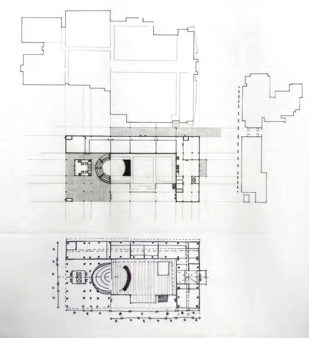
G-01 Site Plan
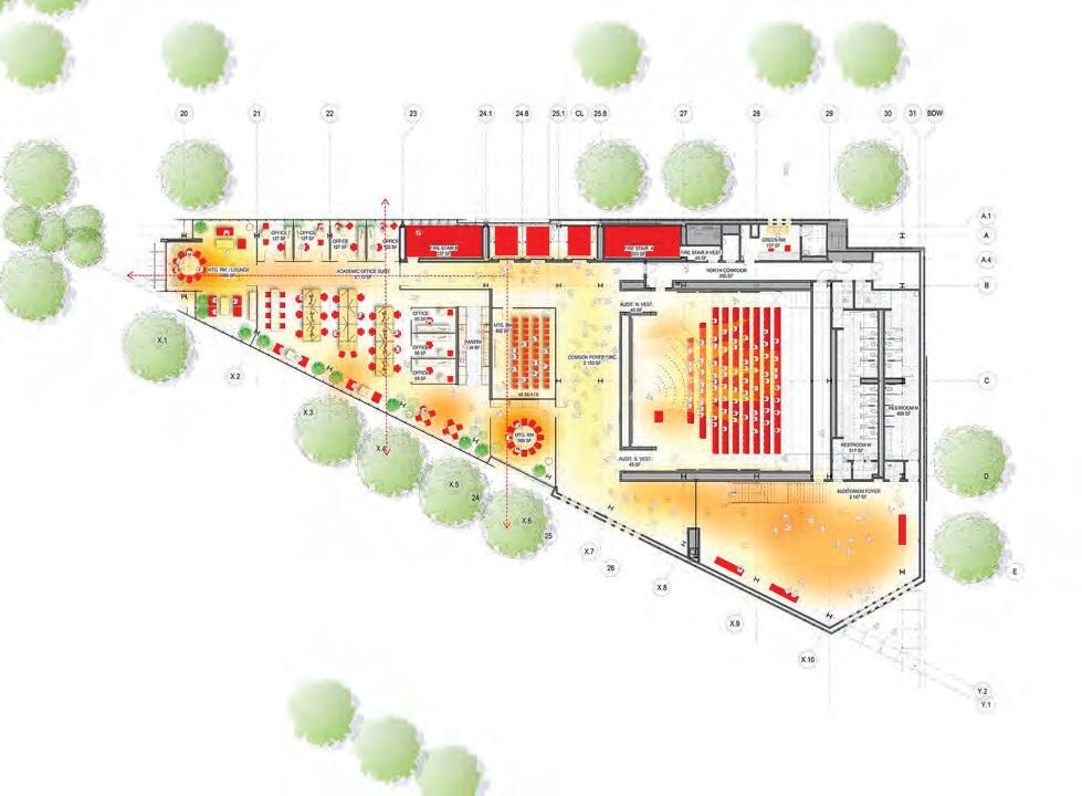
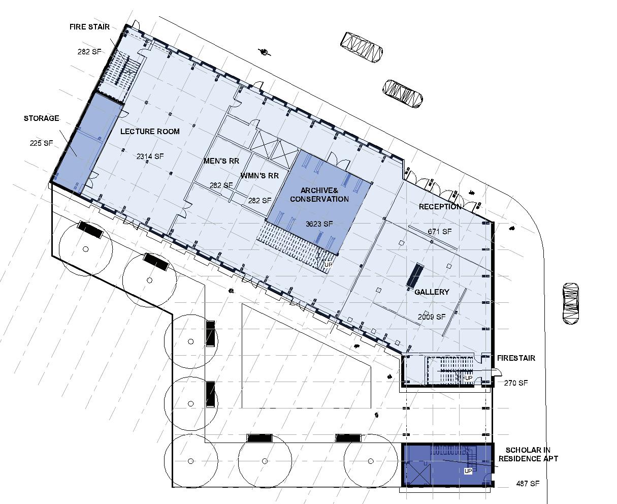
G-02 Ground Floor Plan
G-03 Upper Floor Plan
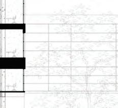
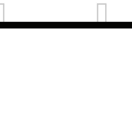
G-04 Building Longitudinal Section
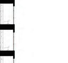
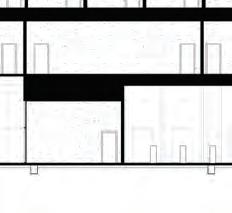
G-05 Building Transverse Sections
G-06 Reading Room Section
G-07 Archive Section
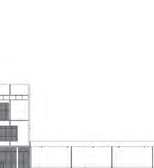
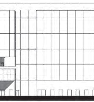
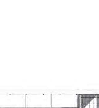
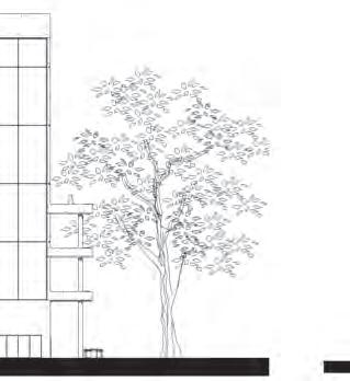
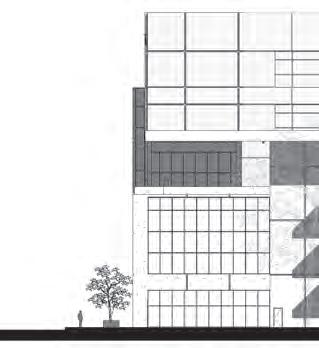
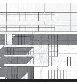
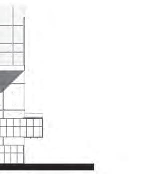
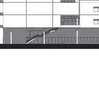
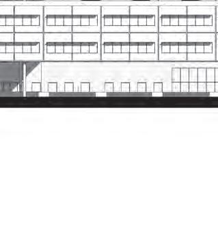
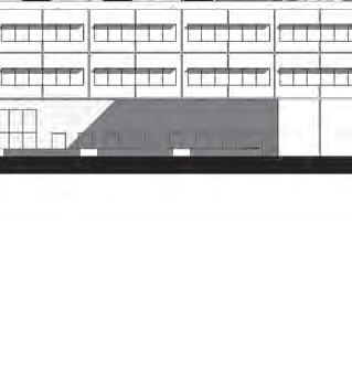
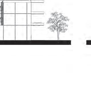
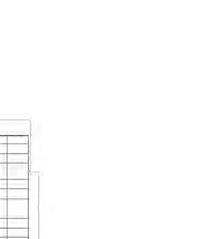
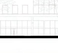
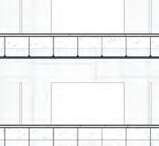
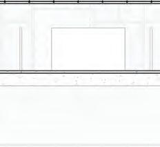
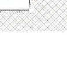
G-08 Building Elevations
G-09 Physical Site Model photographs
G-10 Physical Building/Framing Model Photographs
G-11 Physical Building/Framing Model Photographs
H-01 Detail Design Statement & Axonometric
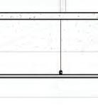
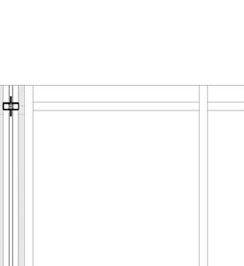
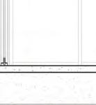
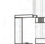
H-02 Wall Section Detail
H-03 Elevation & Plan Detail
H-04 Physical Detail Model Photographs
H-05 Physical Detail Model Photographs
H-06 Physical Detail Model Photographs
PRECEDENT STUDIES
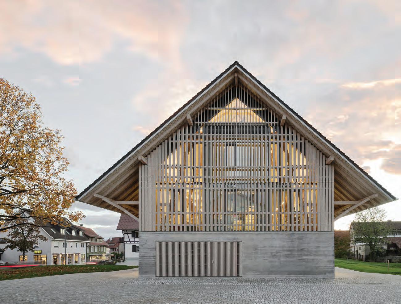
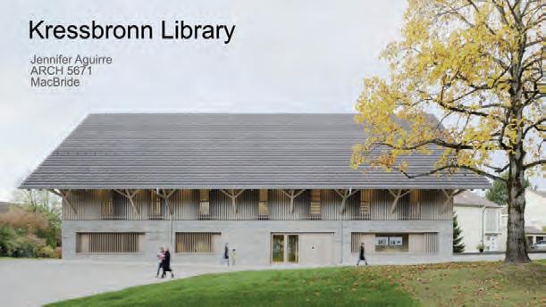
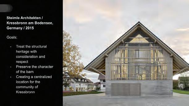
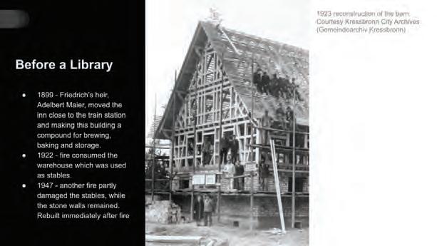
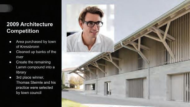
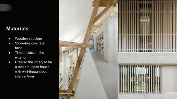
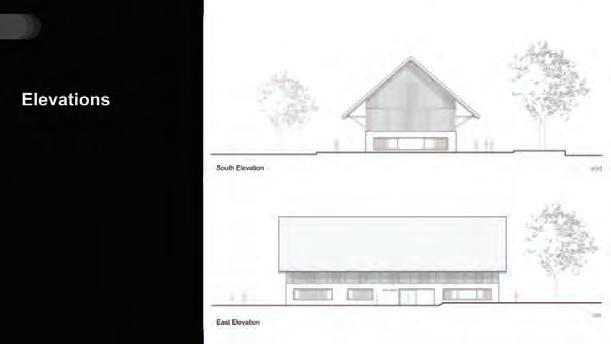
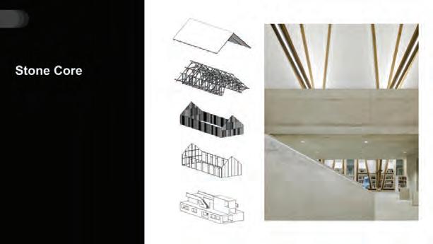
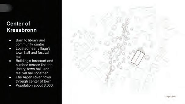
KRESSBRONN LIBRARY
Steimle Architekten / Kressbronn am Bodensee, Germany / 2015
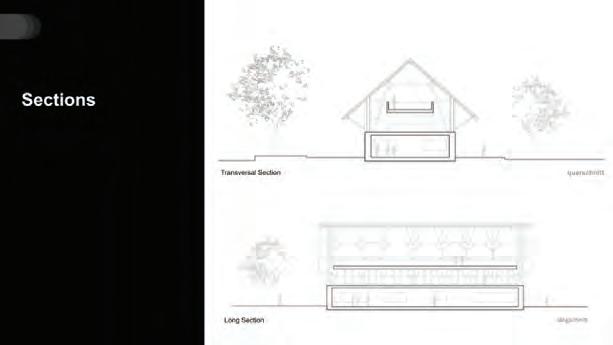
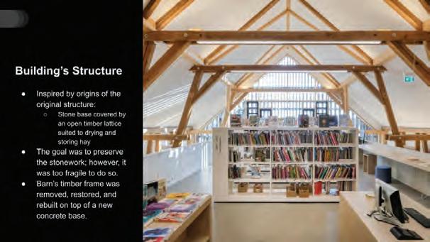
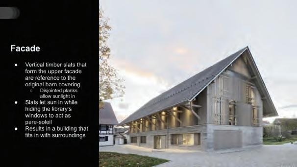
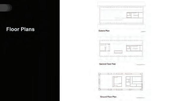
The Kressbronn Library is a renovated agricultural barn, turned into a library in the heart of Kressbronn am Bodensee in Germany. The building holds on to a few original elements such as the concrete base, footprint of building, and preserving the structure. The building plays with the tectonics of a concrete base and exposed interior structure while having a facades that account for the light.
Precedent Study 01 Statement
Precedent
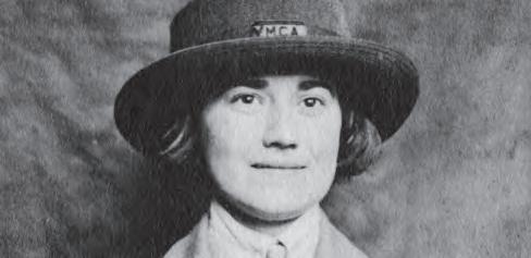
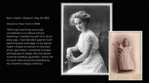
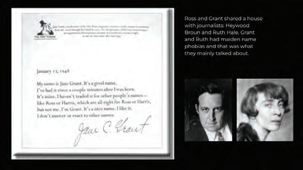
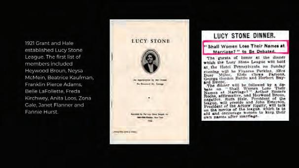
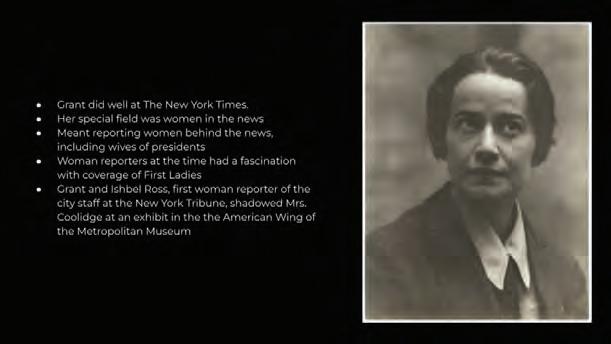
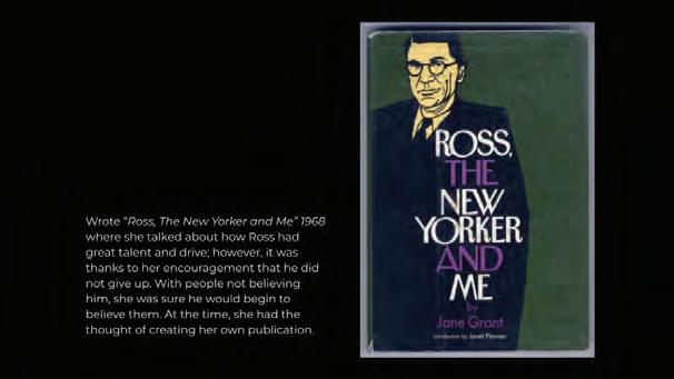
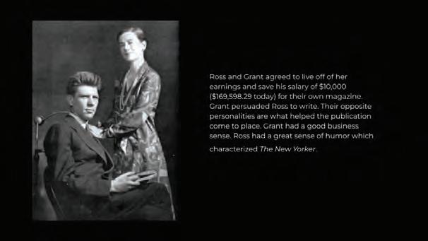
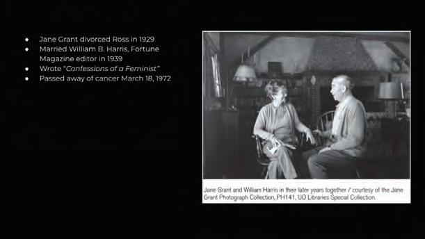
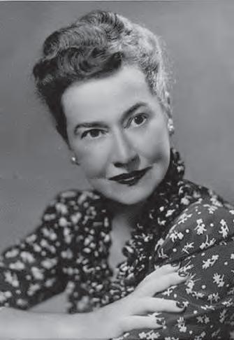
JANE GRANT
Singer / Writer / Feminist
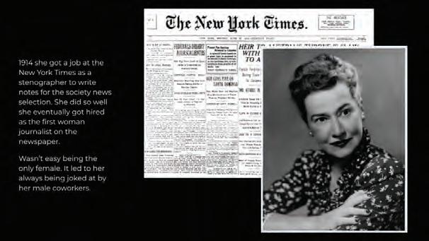
With a heart for singing, Grant moved to New York where she took the journalistic route as she felt it was a more practical choice. There, she was the first woman journalist at the New York Times. She was a member of the Algonquin Round Table where she met her husband, Harold Ross. Together, they started their own magazine, The New Yorker.
Precedent Study 02 Statement
Precedent Study
PROGRAMMING RESEARCH, ANALYSIS & DOCUMENTATION
Programming statement
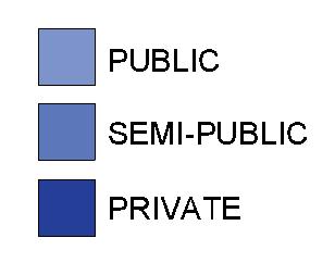
The archive is placed in the center of the building as a glass box and becomes the heart of the building as it extends through both levels. Although the archive is not open to everyone, people can still see what is going on inside as they circulate between both levels. From here, accessible spaces surround the archive making the entire building feel open.
Programming Statement
Columbia University Expansion of Manhattanville Campus
GOALS
Manhattenville Campus to become a new expansion to the Morningside Heights Campus of Columbia University. The new campus will serve as a new symbol for New York and a renaissance to the cultural and social history of crime and violence. The new campus will serve both students and the community.
Columbia University Mission & Goals
Manhattanville Campus Plan
Designers
Renzo Piano Building Workship
Skidmore, Owings & Merrill, urban designers (New York)
Davis Brody Bond
Phase One:
- Jerome L. Greene Science Center (completed)
- Lenfest Center for the Arts (completed)
- The Forum (completed)
- The School of International and Public Affairs.
Looking for a new place that stands as a symbol for New York.
A place for a cultural and social renaissance after a long parenthesis of crime and violence.
Columbia University at Morningside Heights
- District that saw the birth of Jazz
- Marten Luther King’s social struggle
- The Black Panther revolt
- Films of Spike Lee
Manhattanville’s Industrial Past:
West Harlem was the home to many small businesses that stood before the Manhattanville Campus. Through the threat of eminant domain, Columbia University replaced buildings, demolished, or became the landlord of buildings until the final phases of construction took place.
631,740 sq m Long-term Master Plan to include academic, research, recreational, residential, administrative, and support space for the University. Publicly accessible open space, commercial, cultural, and social spaces, were created to engage with the community.
Manhattanville Campus invloves itself more with the community compared to the gated campus of Morningside Heights.
Instead of creating an “Urban Layer” by elevating the campus ground floor from the rest of the community, Manhattanville Campus remained on ground floor in order to tie into public activity, creating a hybrid space. Activities include: retail, restaurants, galleries & performance spaces, health clinics, community meeting space, and more University-community partnerships.
ty-campus
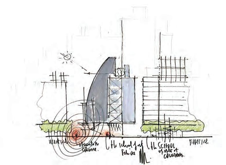
Master Plan Program Anlalysis
Sketches by Renzo Piano Building Workshop https://www.e-architect. com/new-york/columbia-universi-
Manhattanville
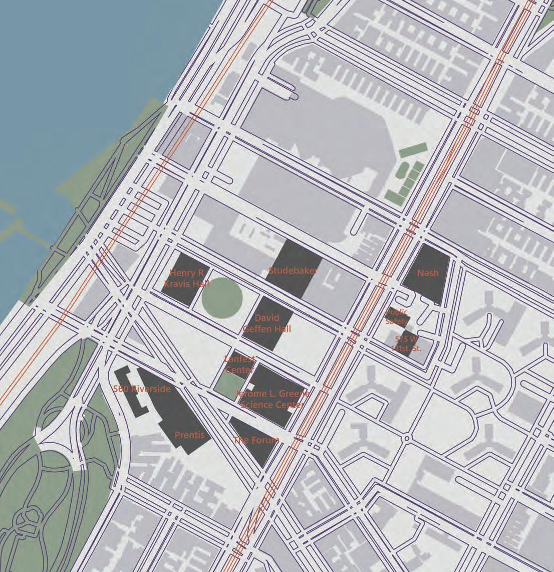
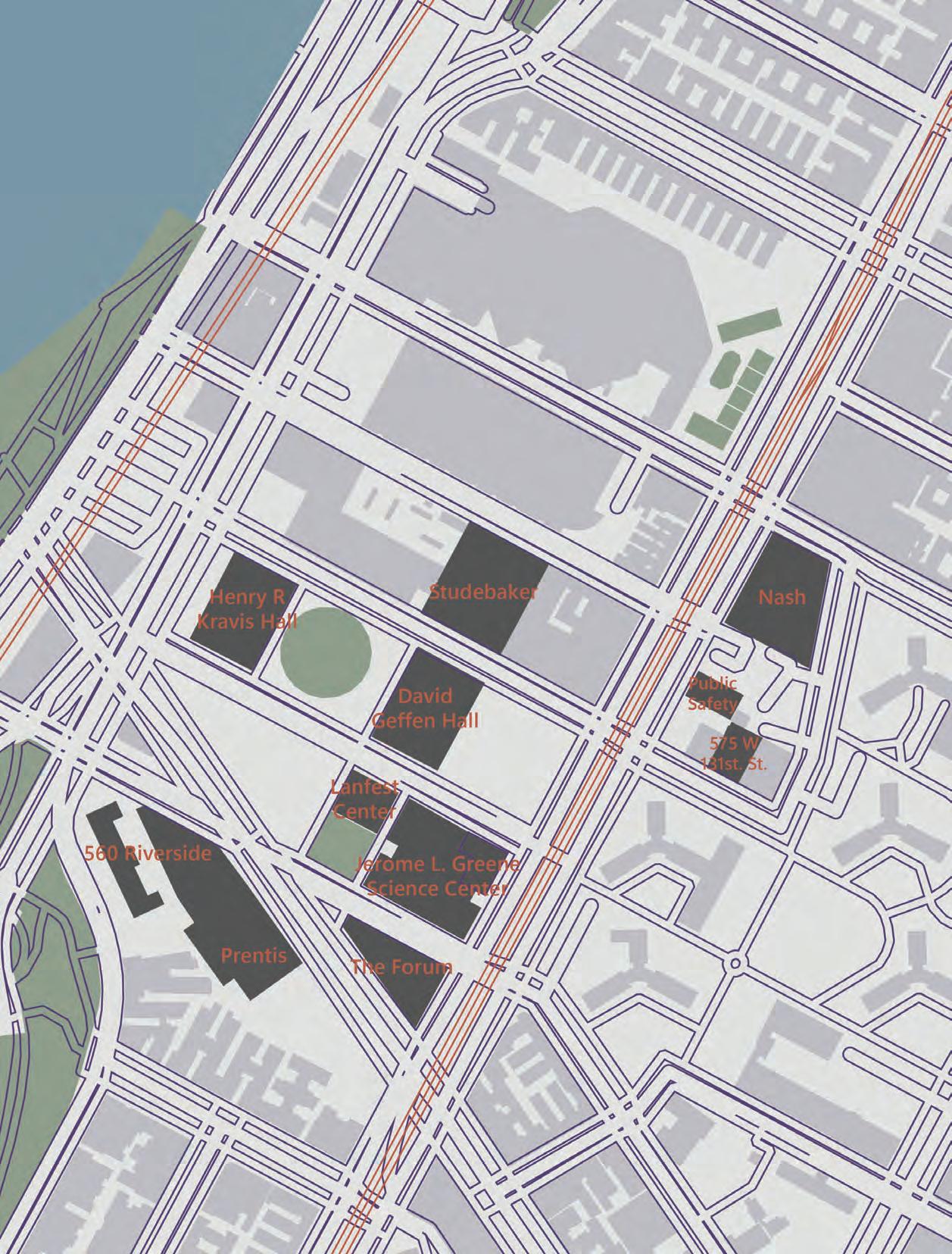
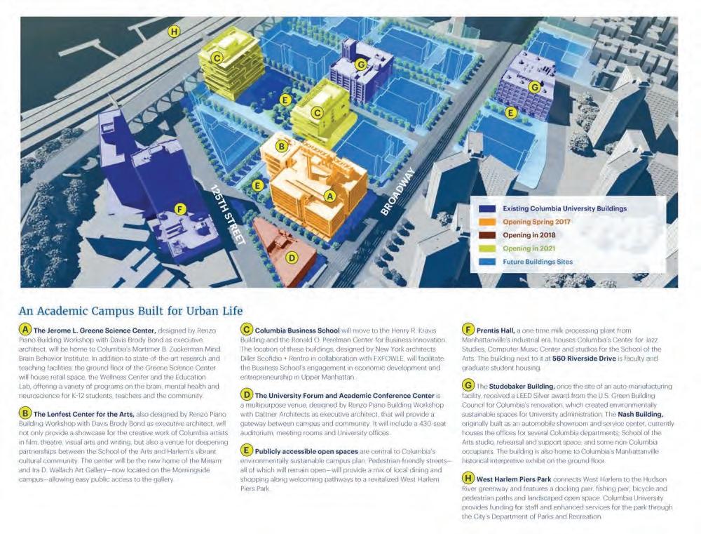
Current Campus Buildings
The Henry R. Kravis Building (Columbia Business School)
Opened 2021
Will facilitate the Business School’s engagement in economic developmentand entrepreneurship in Upper Manhattan.
The Lenfest Center for the Arts
Opened 2017
Will provide a showcase for creative work of Columbia artists in film, theatre, visual arts, and writing. The space provides a venue for partnerships between the School of the Arts and Harlem’s vibrant cultural community. The center will home the Miriam and Ira D. Wallach Art Gallery that is currently at the Morningside campus.
560 Riverside Drive
Existing Building
Faculty and graduate student housing.
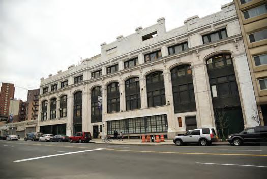
Prentis Hall
Existing Building
Previous milk processing plant from Manhattanville’s industrian era. Currently Columbia’s Center for Jazz Studies. Computer Music Center and studios for the School of Arts.
The Nash Building Existing Building
Previously the automobile showroom and service center. Currently houses the offices for departments such as: School of Arts studio, rehearsal and support space, and some non-Columbia occupants. The building is also the home to Columbia’s Manhattanville historical interpretive exhibit on the ground floor.
Narrative:
The proposed building will add an archive/ reading room building to campus where it will honor a literary figure that relates to the site.
The Forum Opened 2018
A multipurpose venue that will provide a gateway between campus and community. Includes a 430-seat auditorium, meeting rooms and University offices.
The Studebaker Building
Existing Building
Previously the site of an automanufacturing facility. Received a LEED Silver award for the renovation, which created environmentally sustainable spaces for the University administration.
The Jerome L. Greene Science Center
Opened 2017
Home to Columbia’s Mortimer B. Zuckerman Mind Brain Behavior Institute. In addition to state-of-the-art research and teaching facilities, the ground floor includes retail space, the Wellness Center and the Education Lab.
Building Program
Analysis & Narrative
Program Tabulation
Public Program
Entry / Reception / Control Desk ≈ 500sf
Building entrance, reception-informationcontrol desk, security, lobby, and seating area
Exhibit / Gallery spaces ≈ 1000sf
Areas for permanent and temporary exhibitions. Minimum of one gallery dedicated to the author and one dedicated to the literary school. Galleries may double as event spaces.
Lecture Room ≈ 1500sf
A room for lectures, public readings, and educational programming. Capable of holding 50-75 people with non-fixed seating. Easy access and public visibility of events in this space are important. Provide adequate and directly adjacent storage for chairs, equipment, catering items, and events.
Semi-Public Program
Reading Room ≈ 1000sf
Area for study and research connected directly to the archive/document storage areas. Access to this room is limited to scholars or by appointment. The furnishings, lighting, and interior design of this space make it the heart of the entire building.
Archive and Conservation ≈ 3000sf
The archive itself is a storage area for the author’s papers and documents. It must be fully secured and controlled in terms of fire protection, UV radiation, temperature, and humidity. The archive may, however, also be visually accessible and reinforce the larger architecture and movement through
the building. A conservation area for repair, restoration, and cataloging should be included within this space.
Non-Public Program
Scholar-in-Residence Apartment ≈ 1000sf
The Archive building is to contain a private apartment for a Scholar-in-Residence as part of its educational and research mission. It is a one-bedroom apartment with a separate and/or private entry.
Building Services
Administrative, Archivist, and Security offices: provide offices and work spaces as required. Assume that at least one Administrative and one Security person will be in the building during all operating hours. Archivists, curators, and other staff are also likely to be regularly in the building.
Public Restrooms:
number & fixture count based on occupancy; must meet IBC & ADA codes.
Utility room(s) provided based on proper identification & location of building systems. These include:
- heating/cooling/ventilation (HVAC) systems
- electrical & lighting (including electrical generation) systems
- plumbing/hot water/rainwater/fire suppression systems
- communications and security systems
Loading and Custodial area(s)
Circulation & Conveyance: Building accessibility and egress must meet IBC requirements.
Total ≈ 11,000 sf
Exterior Space Requirements
Outdoor Event Space
Site design beyond the building’s footprint is required but will vary based on the exact siting and building scheme. One defined or “contained” outdoor event space capable of hosting 30 people (min.) is required. This may be a courtyard, lawn, patio, terrace, balcony, or other space that can be utilized al fresco. Preference is for an outdoor space “at grade” rather than one contained within the building itself. Of course, while an infill building will have a different response to its site than a stand-alone one, addressing the Manhattanville master plan in a conscious, designed manner must be evident.
Required Program for Proposed Archive/ Reading Room Building for Columbia University / Manhattanville Campus.
Building Program & Tabulation
SITE RESEARCH, ANALYSIS & DOCUMENTATION
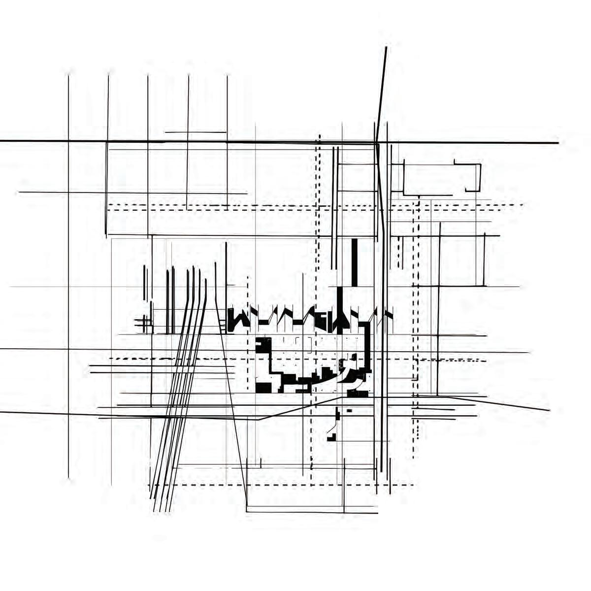
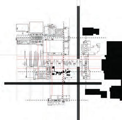
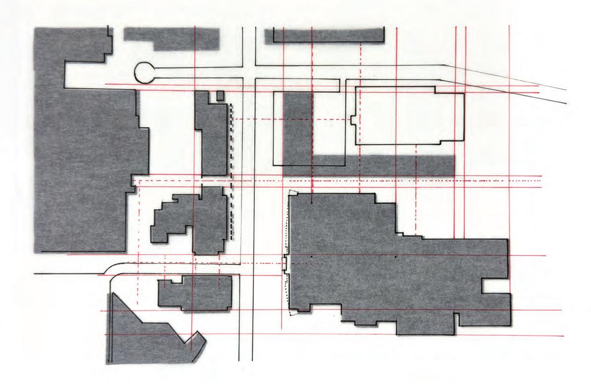
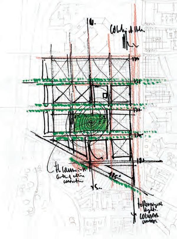
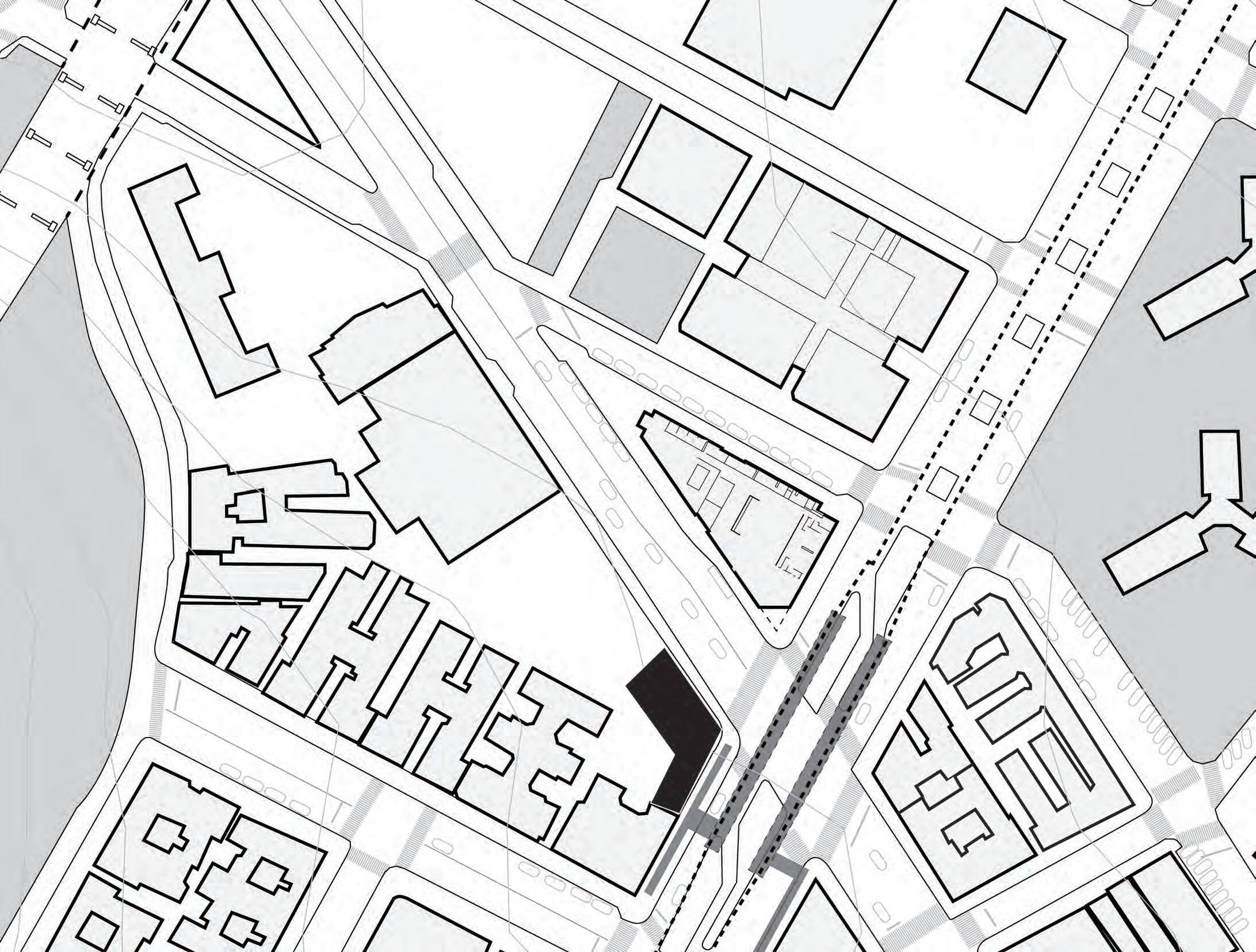
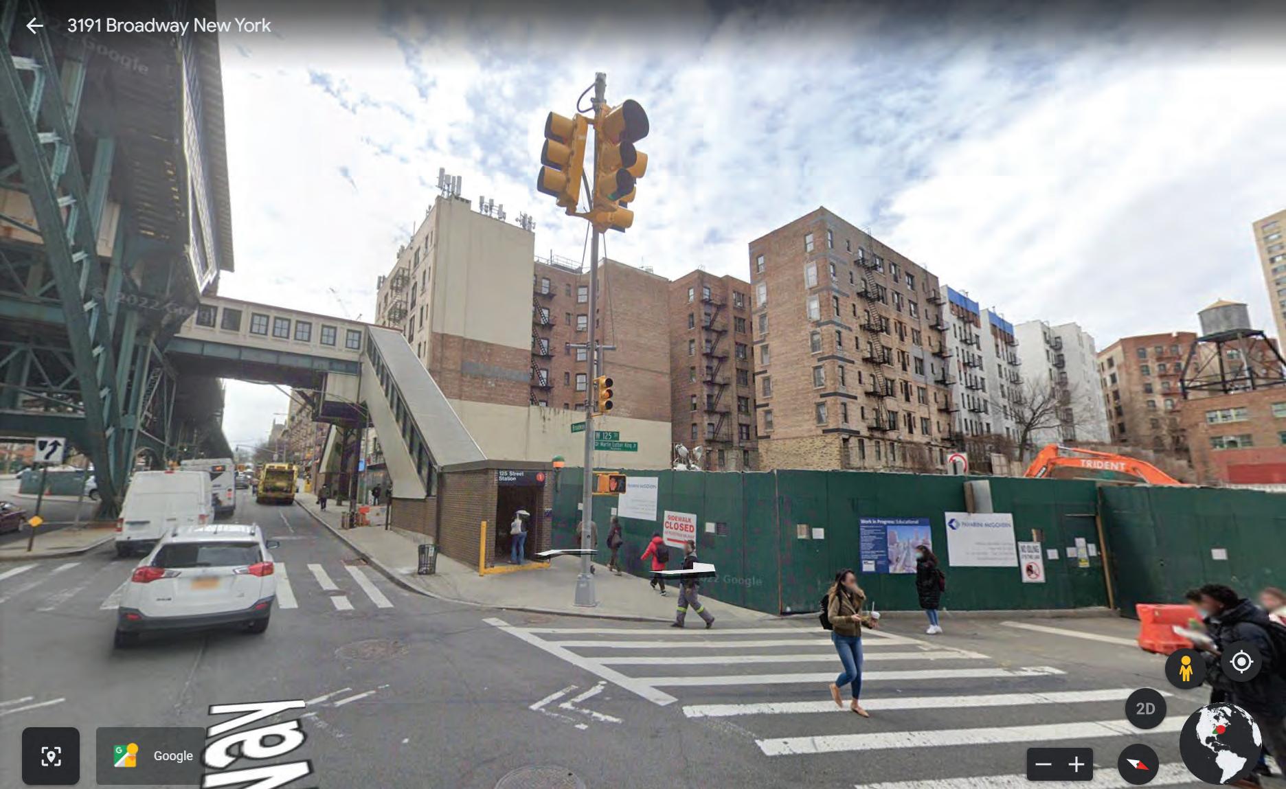
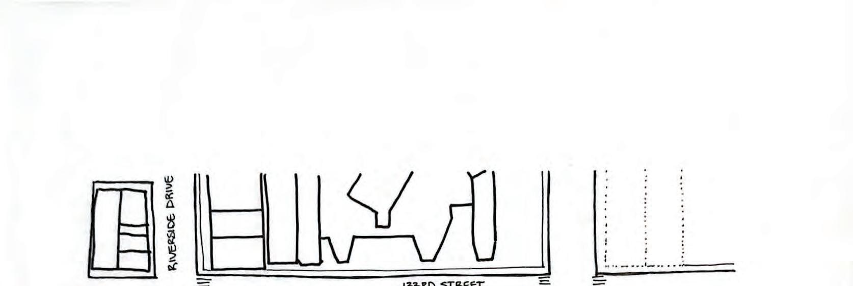
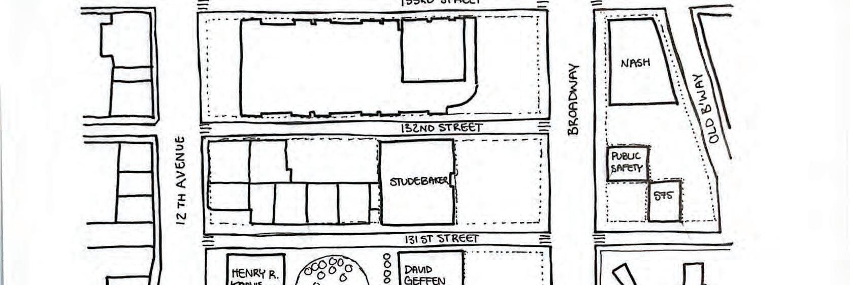
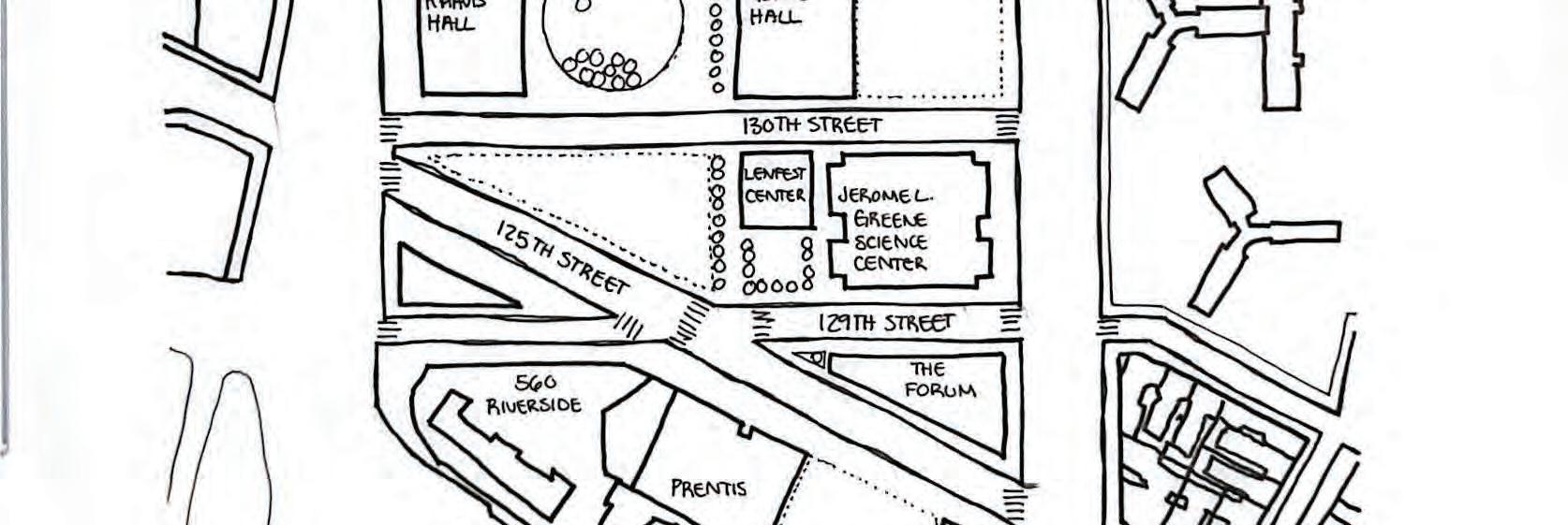
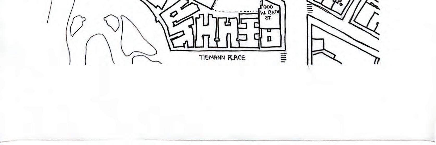
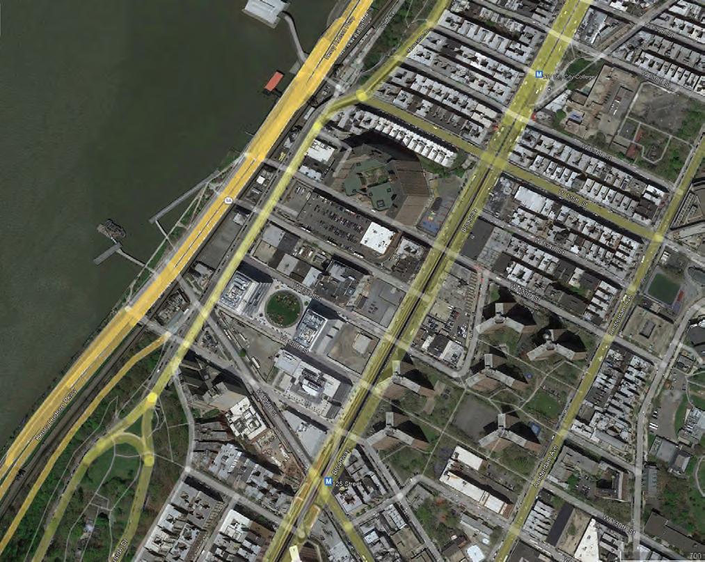
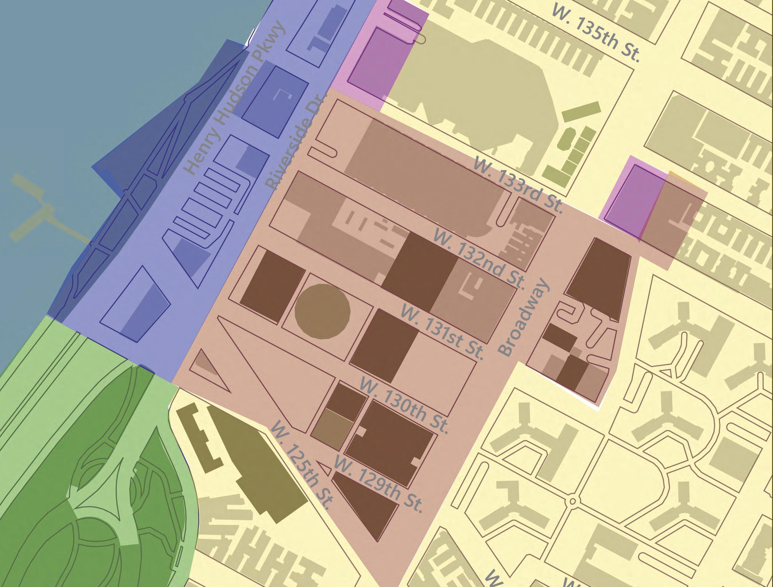
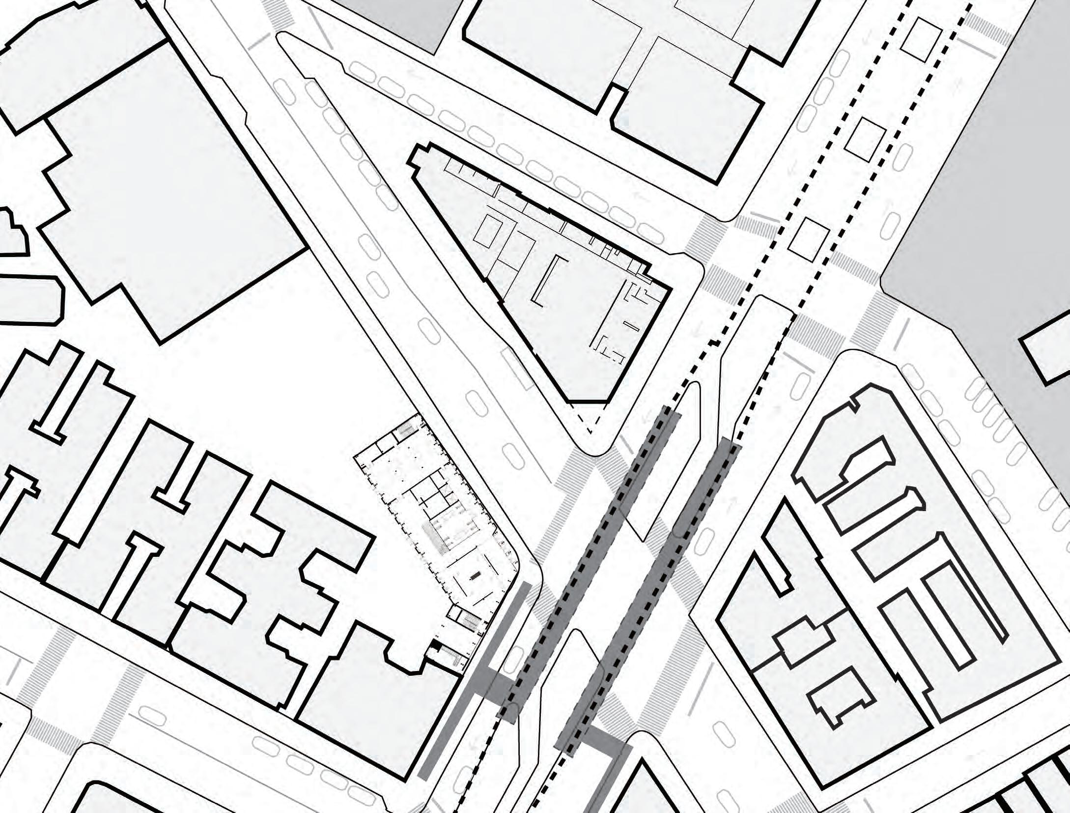
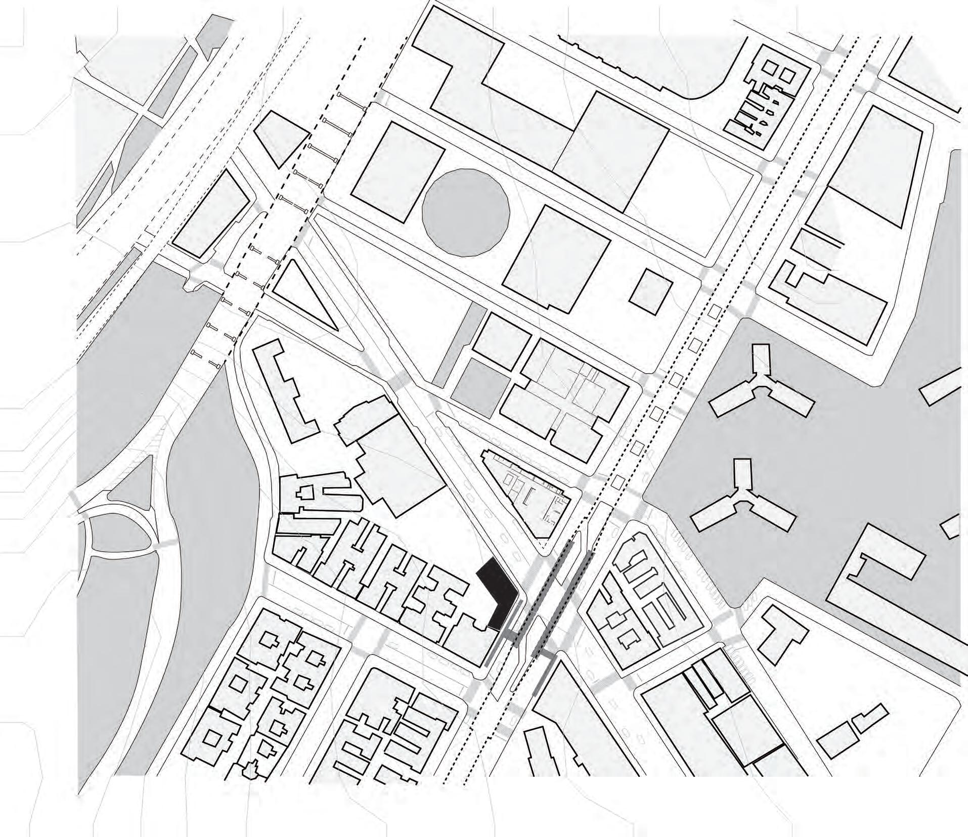
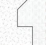
The footprint of the building was decided based on the surrounding building, axis, and circulation. The main driving point was the Renzo Piano circulation between the Forum Building and Jerome L. Green Science Center. This footprint allows for the Grant Archive to become the beginning of the Manhattanville campus on 125th Street and Broadway, replacing the Forum as the beginning point of the campus. The footprint also considers the train entrance on Broadway Street, the use of an entrance on the corner, and the need for a private enclosed courtyard.
Site Design Statement
a.
Renzo Paino’s circulation plan was considered as it shows how people will be walking through the Forum Building from the Jerome L. Green Science Center onto 125th Street where they will see the edge of the building. Furthermore, this feature was a deciding factor to create the edge of the Grant Archive.
b. The Forum Entrance
The entrance to The Forum was located on the corner of 125th Street and Broadway. The Grant Archive reflects the entrance on the opposite side of 125th Street to maintain the connection of a busy entrance to campus and consider pedestrians crossing at the intersection.
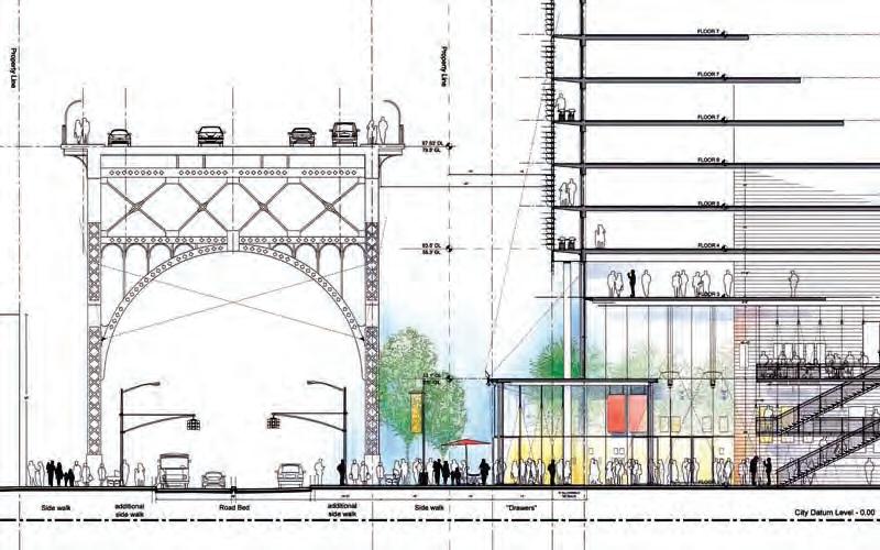
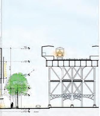
c. Train height
The train height was considered to account for possible views from the archive building to Broadway.
d.
View of the train entrance
Along with the height of the train, the entrance needs to be considered in what views it will obstruct or how much room will be available for the building’s footprint without taking away space from the sidewalk.
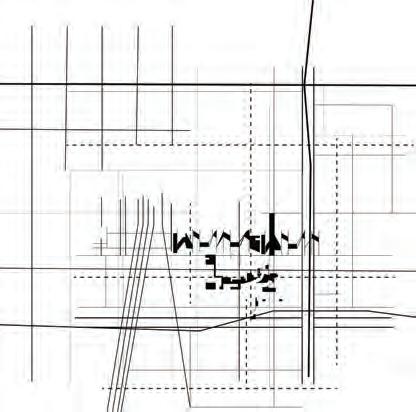
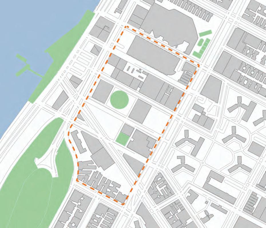
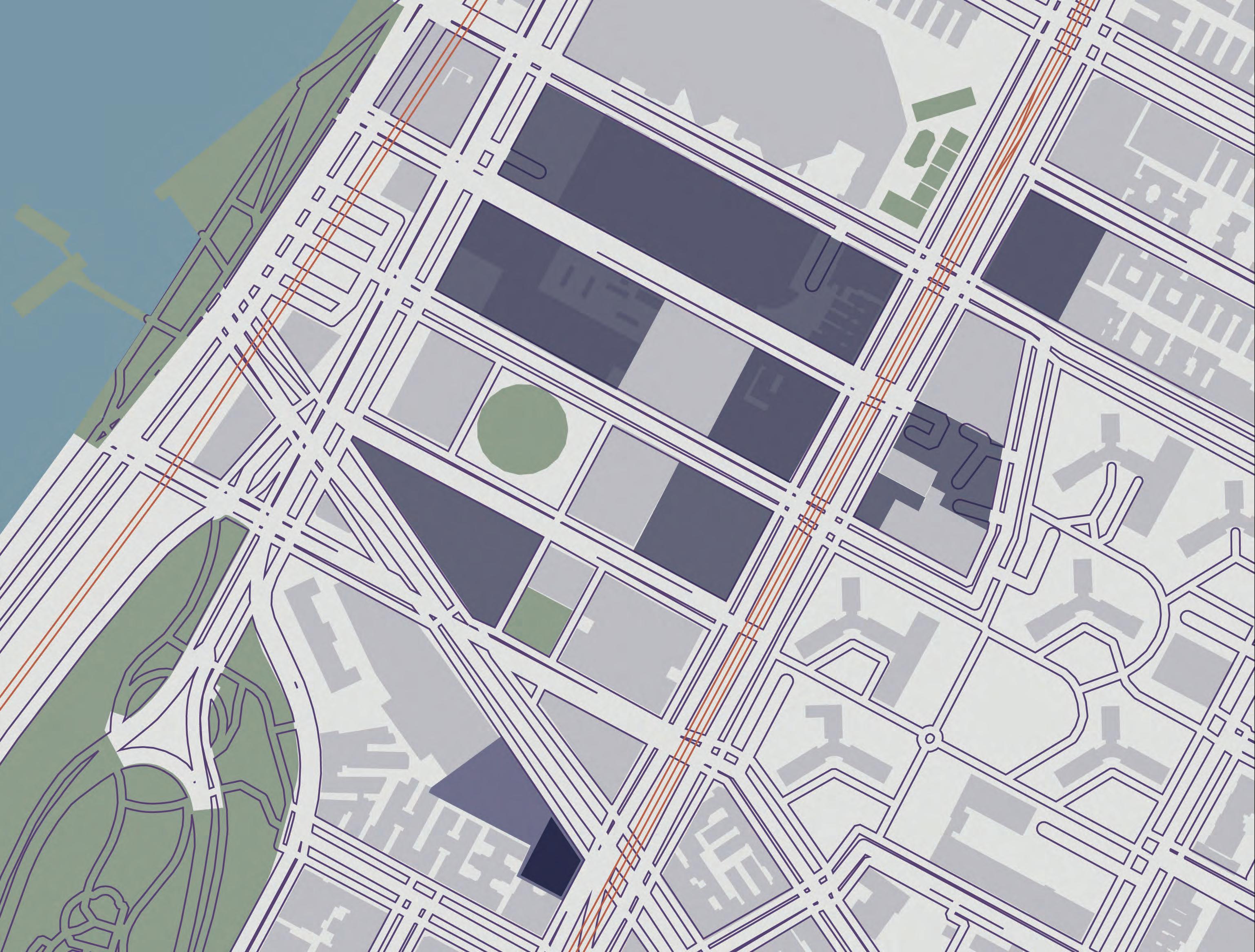
The Manhattanville Campus of Columbia University has a lot of room for growth. With the new master plan, the neighborhood will be creating a turnaround as more educational buildings fill the area. A large slope takes place at the beginning of campus and slopes down to the Hudson River. There are major roads, highways, and viaducts that fill the exterior. New additions to the campus will need to consider current residents, future students, safety, accessibility, and topography.
Formal Analysis Drawing
Existing Campus Program Campus Perimeters Surrounding Streets a. b. c.
Site Circulation Diagrams
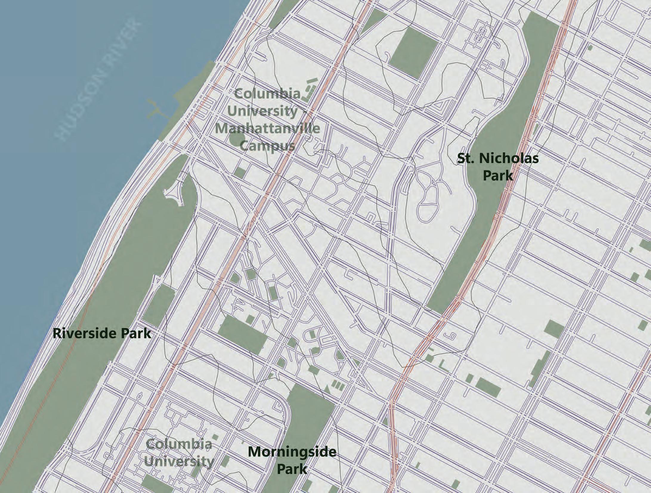
Riverside Park
- Stretches 4 Miles from 72nd to 158th St. along the Hudson River
Morningside Park - 30 acres
- Upper Manhattan
- Bounded by 110th Street and 123rd Street
St. Nicholas Park - 23 acres
- Between Harlem, Hamilton Heights, and Manhattanville
Marcus Garvey Park - 20.16 acre
Riverbank State Park
- 28 acre
- 69 feet above the Hudson River
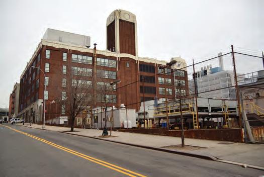
Manhattanville’s Industrial Past
Contained a car wash, gas
at least
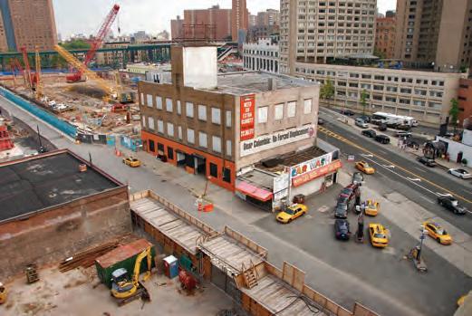
Before the Columbia Expansion, the West Harlem area was home the to Industrial Architecture that included businesses such as: slaughterhouses, dairy factories, warehouses, restaurants, car shops, gas stations, and tenant buildings.
Previously the1924 automobile factory that later became the Borden Milk Company. Currently houses administrative offices for Columbia.
West 125th Street and 12th Avenue
station, and warehouse for
50 years.
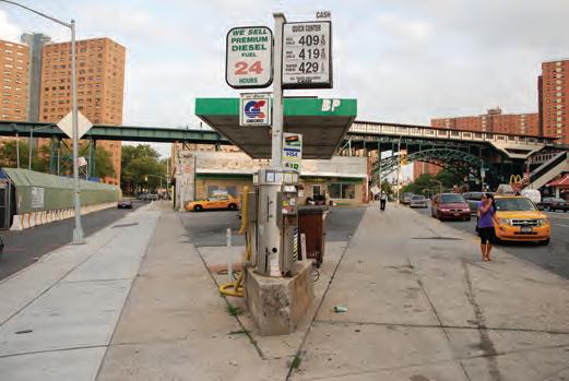
West 129th Street and West 125th Street One of the last three gas stations in the neighborhood.
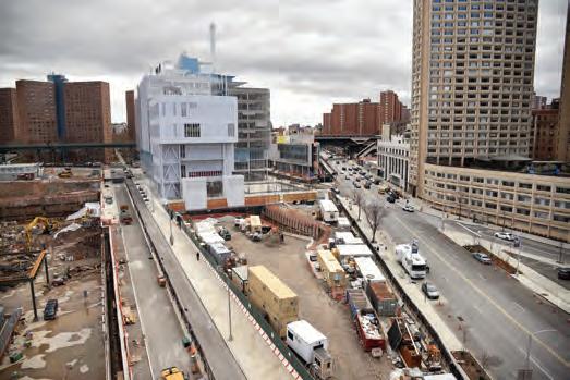
West 125th Street and 12th Avenue (Today)
Empty lot used for construction. Columbia has not yet announced what building may be inserted here.
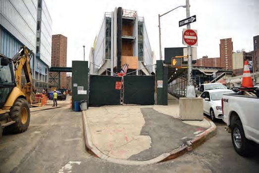
West 129th Street and West 125th Street (Today) New home to the University Forum and Academic Conference Center.
Prentis Hall
Previously The Sheffield Farms dairy plant that opened in 1911 that included a small exhibit nearby about Manhattanville’s milk processing past. Now is used by Columbia for art studios and offices.
Photography and Photo Essay by Nathan Kensinger on NY Curbed https://
Information from: https://www.e-architect.com/ new-york/columbia-university-campus
M1-1 Districts
Designated for areas with light industries.
C6-1 Districts Commercial Areas that require central locations or serve the entire metropolitan region.
C6-2 Districts Commercial Areas that require central locations or serve the entire metropolitan region.
R7-2 Districts
Medium-density apartment house districts that encourage lower apartment buildings on smaller lots and, on larger lots, taller buildings with less lot coverage.
PARK
Public Parks such as: playground, beach, parkway, or roadway within the jurisdiction and control of the New York City Commisioner of Parks and Recreation.
Planning/zoning/ municipal Analysis
Diagram
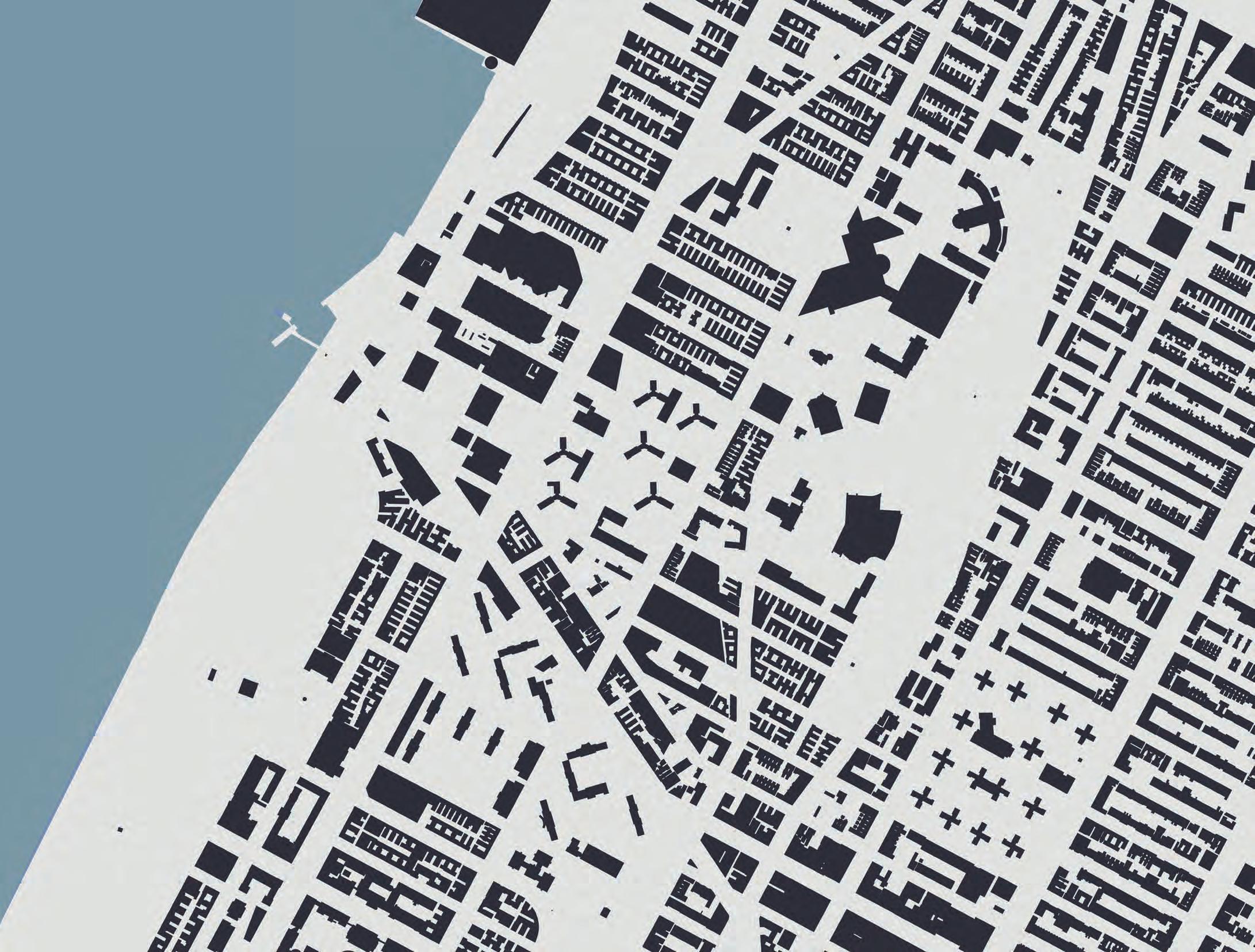
Neighborhoods
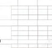
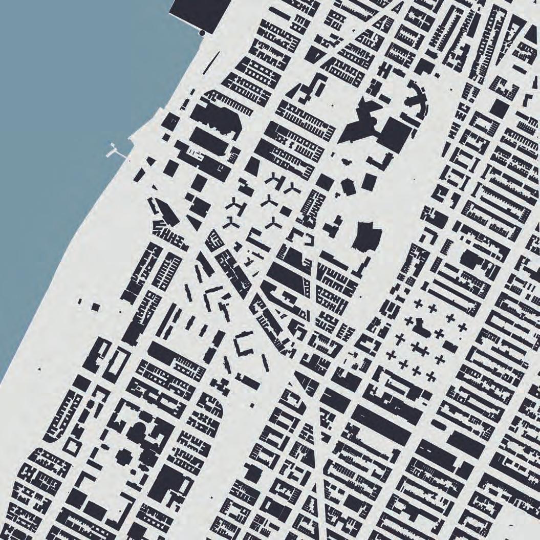
Figure Ground
TECTONICS / CONCEPT DESIGN / DESIGN CHARRETTE
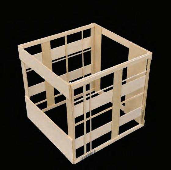
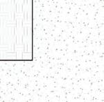
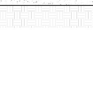
After Charrette 01’s challenge, Charrette 02 became a 5 sided cube but maintained the use of creating unique faces on each side with thick and thin components. The challenge that this charrette needed to solve is making sure the randomization of the faces would allow for them to connect together and rely on each other to make a 5 sided cube. Making pieces rely on each other led to the tectonic path produced in this project.
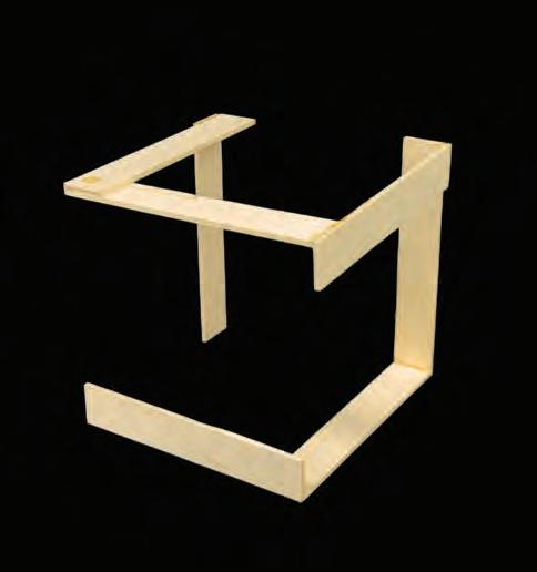
The design of a four-sided cube was assigned for Charrette 01 where this cube had thick and thin components. This cube has four different sides with different patterns but by following directions on how to be constructed, could be replicated in a similar manner in which the cubes will not look the same but will function the same. The challenge after creating this charrette is, how can you make the components on the faces rely on each other to stay up without needing a frame. This led to the production of Charrette 02.
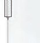
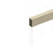
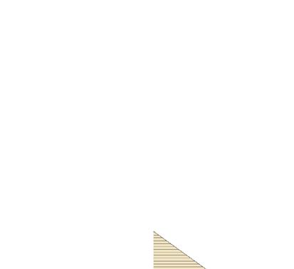
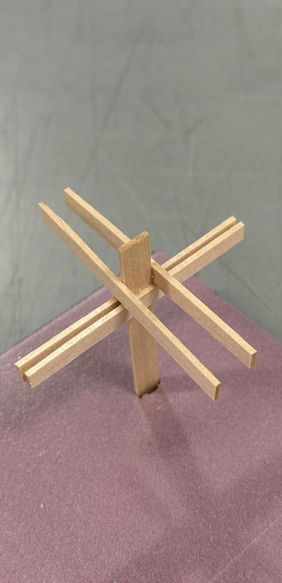
The use of the tectonic design came from a series of charrette models where the construction of structure and tectonics was explored through thick and thin components. From the charrettes challenges, the final tectonic design focused on the joinery item (represented to the right) throughout the building. The joinery was designed with components that are leaning on one another in order to maintain a connection with rigidity and strength to withstand dead, live, and lateral loads within the building. By looking at the two charrette designs, you will see what challenges were initially imposed and led to the development of the final tectonic design.
Tectonic Path Statement
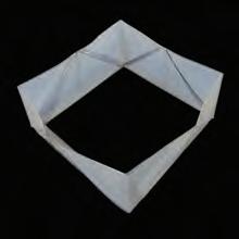
Charrette 02:
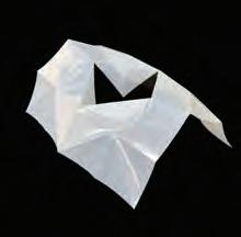
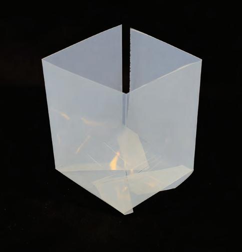
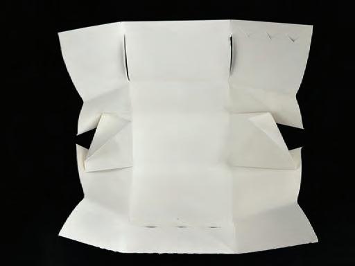
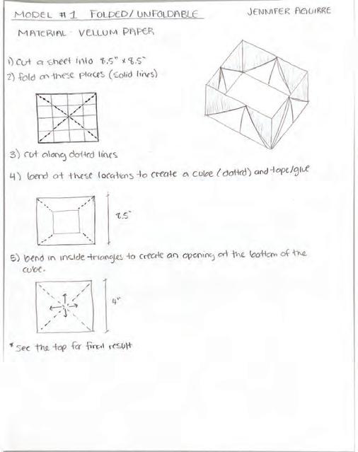
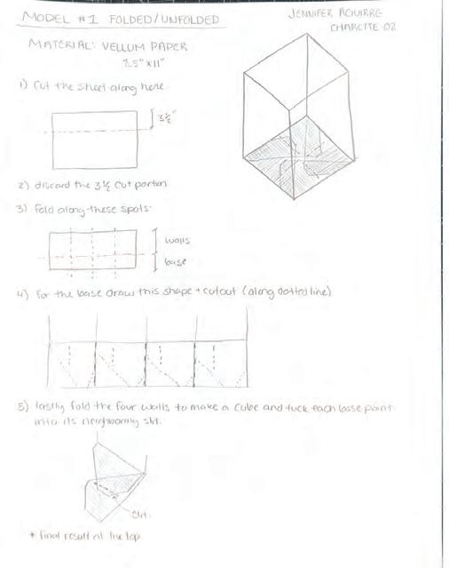
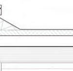
Model #1 Folded/Unfolded
MATERIAL: VELLUM PAPER
TOP: Final Result
The top showes a shape that was cut out of a sheet of vellum paper to create 4 walls but folding after making cuts.
BOTTOM: Attempts
Incorrect attempt where it did not fold into the 4 walls; however, still creates a shape of its own.
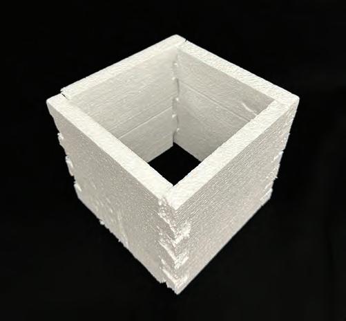
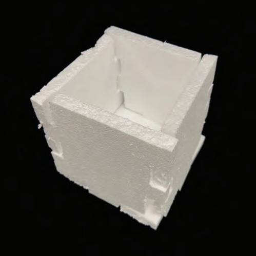
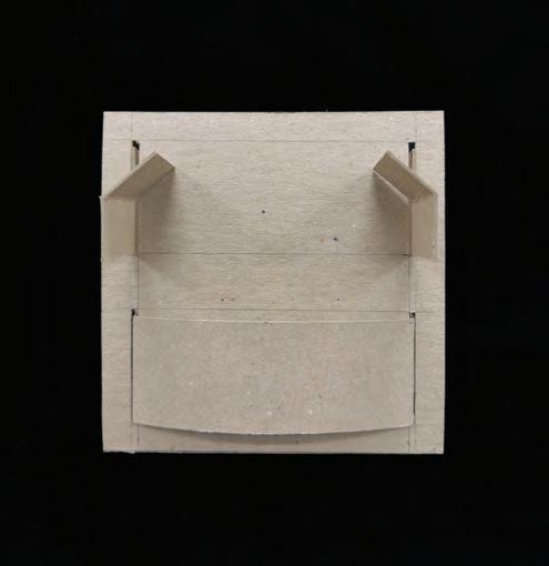
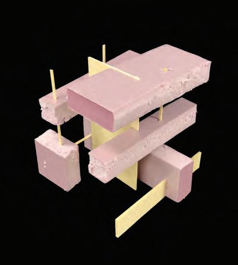
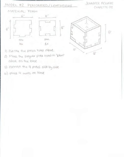
Model #2 Perforated/Lightweight
MATERIAL: FOAM
Using a material that is thick to provide stability but is very lightweight. This would be beneficial if multiple were to be stacked on top of each other like the banker’s box. This material has been used to create coolers that are affordable, light, and provide insulation to keep objects inside at a desired temperature.
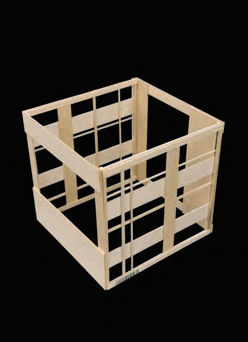
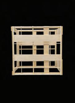
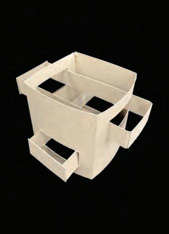
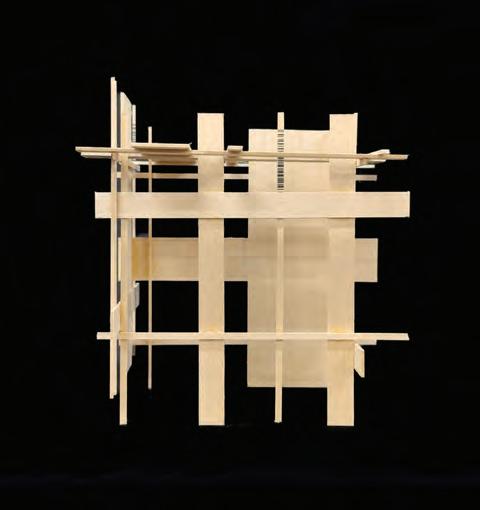
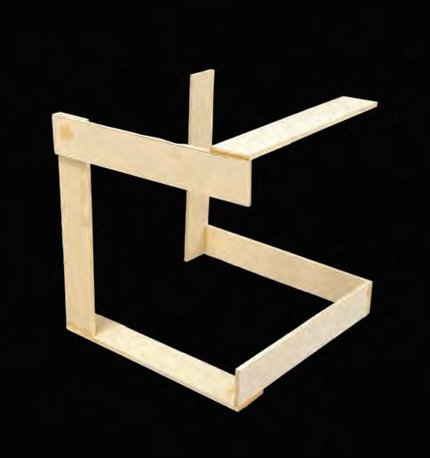
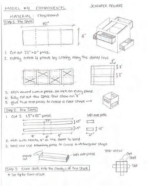
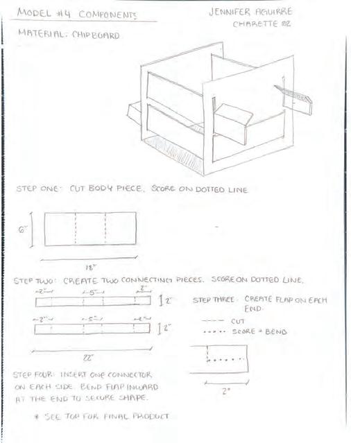
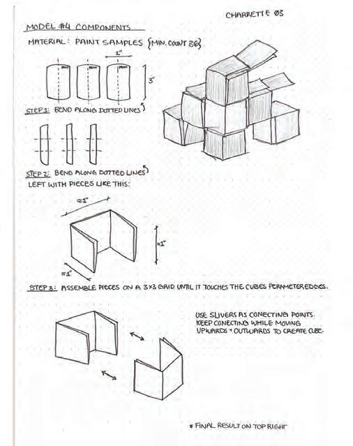
Model #4 Components
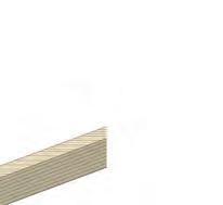
MATERIAL: BASSWOOD
Creating grids that will organize spaces and an order but also provide structure to create the 4 sides to the cube. All while verying in thick and thin components working together to provide stability.
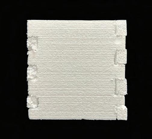
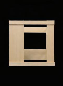
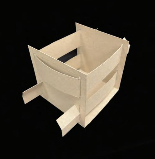
MATERIAL: CHIPBOARD
Providing 4 sides of the box with function by creating components that move in and out, utilizing all 4 sides.
Next Challenge: Using the components to make the walls stand without using glue.
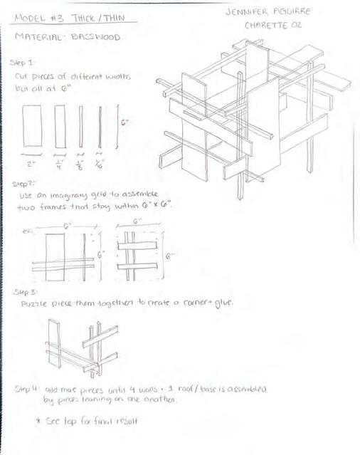
Model #3 - Thick/Thin
Charrette 01: FOURS Models & Statement
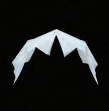
Model #1 Folded/Unfolded
Model #2 Perforated/Lightweight
Using vellum to bend and cut to a shape of a box with five sides without using any types of adhesives. Improvements that could be made is to plan for an extra piece that will connect the gap, making it an enclosed five sided cube.
Model #3 - Thick/Thin
MATERIAL: BASSWOOD
Using the structure of creating grid planes that intersect with eachother, creating a five sided box. This model eliminates the use of a typical frame and uses each piece to lean and rely on eachother. Takeaways from this model include, exploring ways to minimize or eliminate the use of adhesive.
Using foam to take advantage of its lightweight, strong structure. Using simple connections to make the cube an easy to assemble box. Takeaways from this model include exploring other types of foam such as, insulation foam.
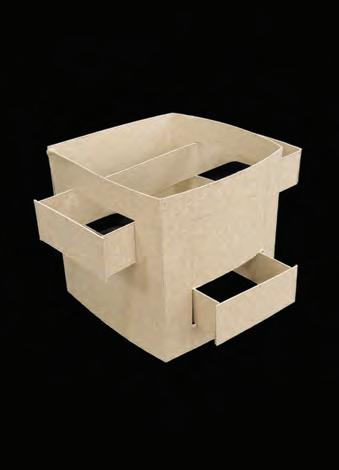
Model #4 Components
MATERIAL: CHIPBOARD
This model explores ways of slots becoming the structure to creating 4 standing walls and a base: 5 sided box. This box can be constructed and deconstructed simply by unlatching the wings at the end of each slot. This helps for putting away the box or constructing it in a simple method.
MATERIAL: VELLUM PAPER
MATERIAL: FOAM
Charrette 02: FIVES Models & Statement
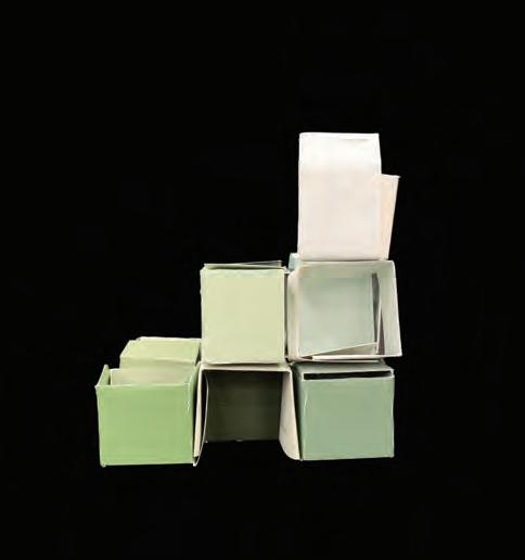
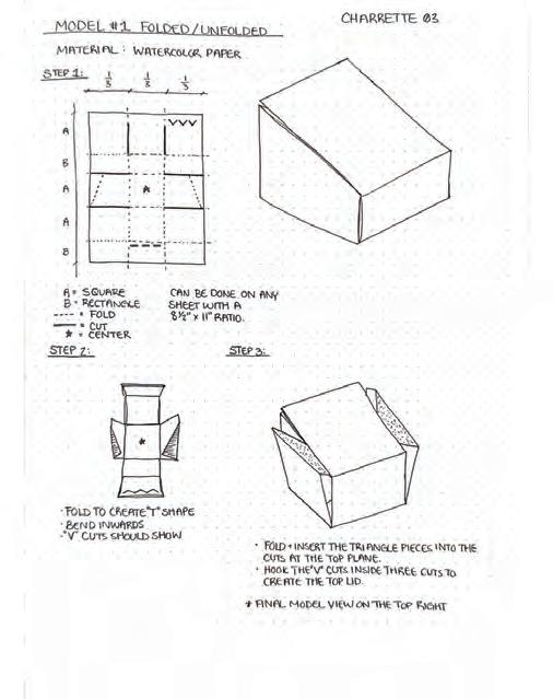
Model #1 Folded/Unfolded
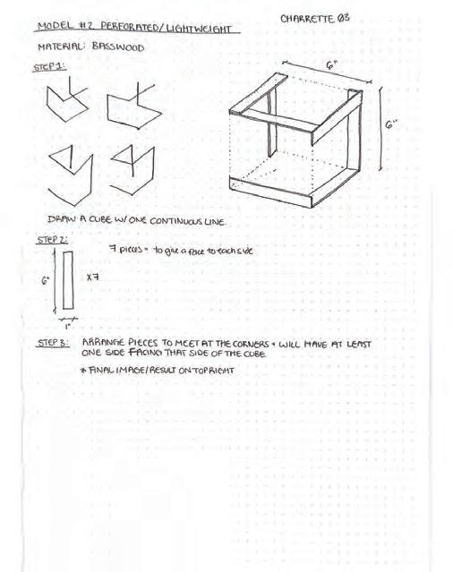
Model #2 Perforated/Lightweight
WATERCOLOR PAPER
Using a single sheet to create a complete inclosed cube. Made by folding and cutting portions of the paper and studying atachments to avoid using any form of adhesive.
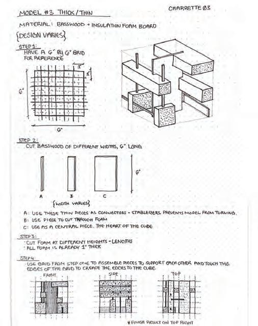
Model #3 - Thick/Thin
Working more with thick and thin pieces instead of just increasing the width of basswood. The thick pieces help achor the model while the basswood helps stabilize.
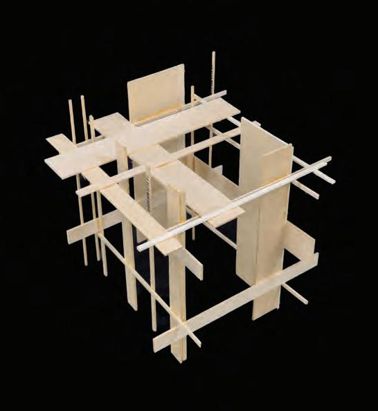
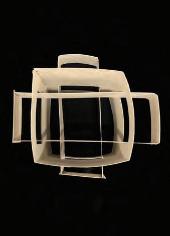
Creating a 6 sided cube by using one continuous “line” by using basswood pieces. Each side will have access to at least one flat piece.
Model #4 Components
Using a material that is not practical to make a 6 sided cube. By using slivers within the pieces, the model begins to come together. Takeaways include, adding more pieces to create strong flat surfaces to all 6 sides.
MATERIAL:
MATERIAL: BASSWOOD
MATERIAL: INSULATION BOARD & BASSWOOD
MATERIAL: PAPER/PAINT SAMPLES
Charrette 03: SIXES Models & Statement
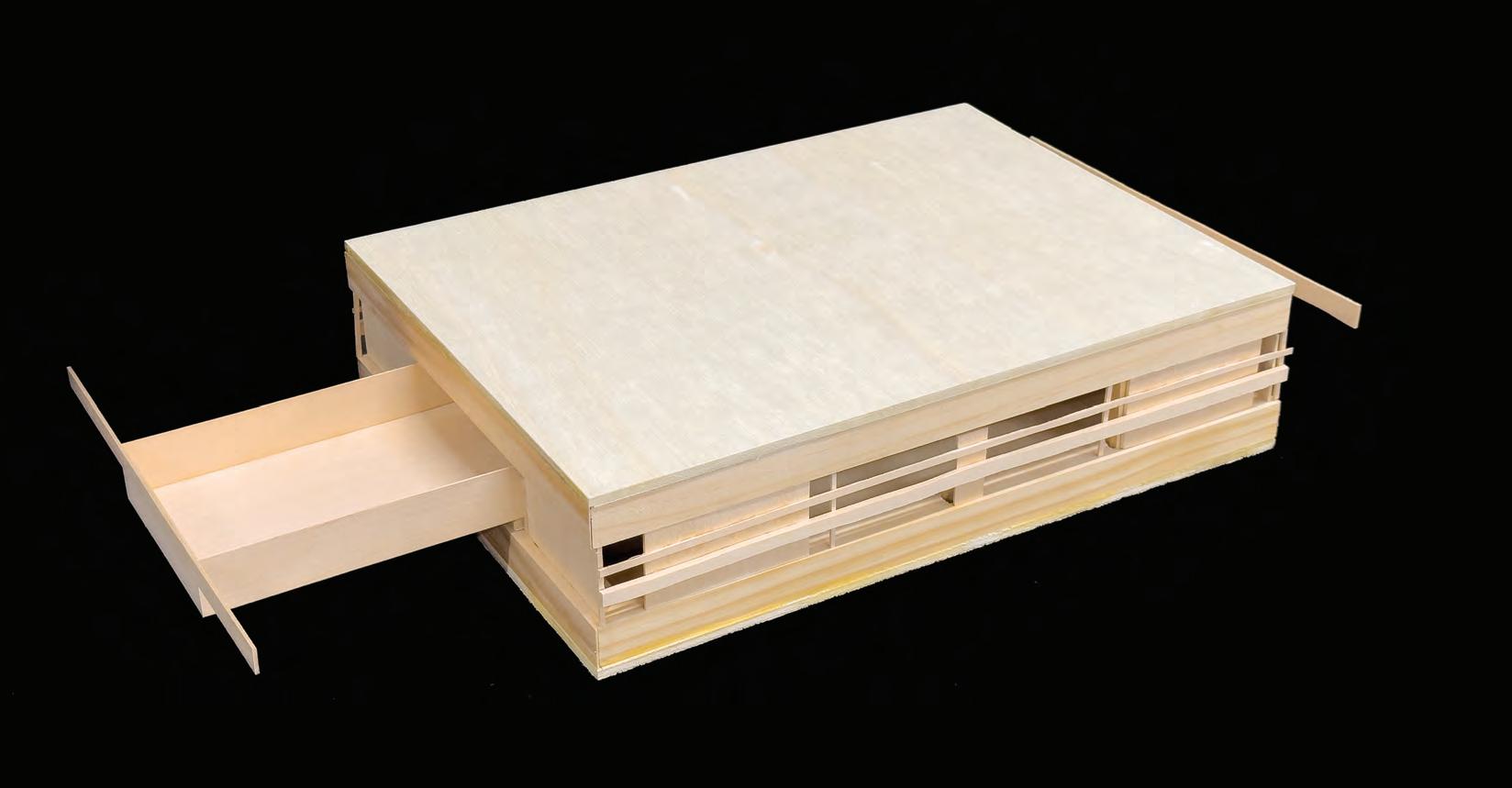
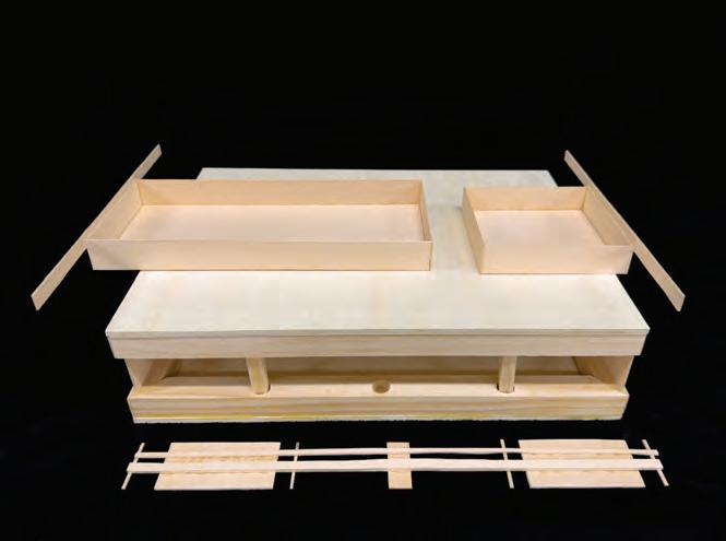
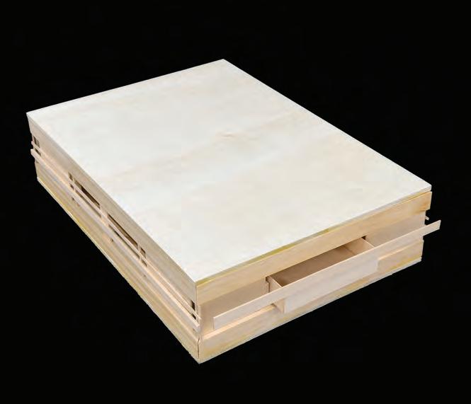
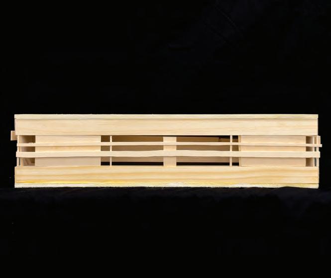
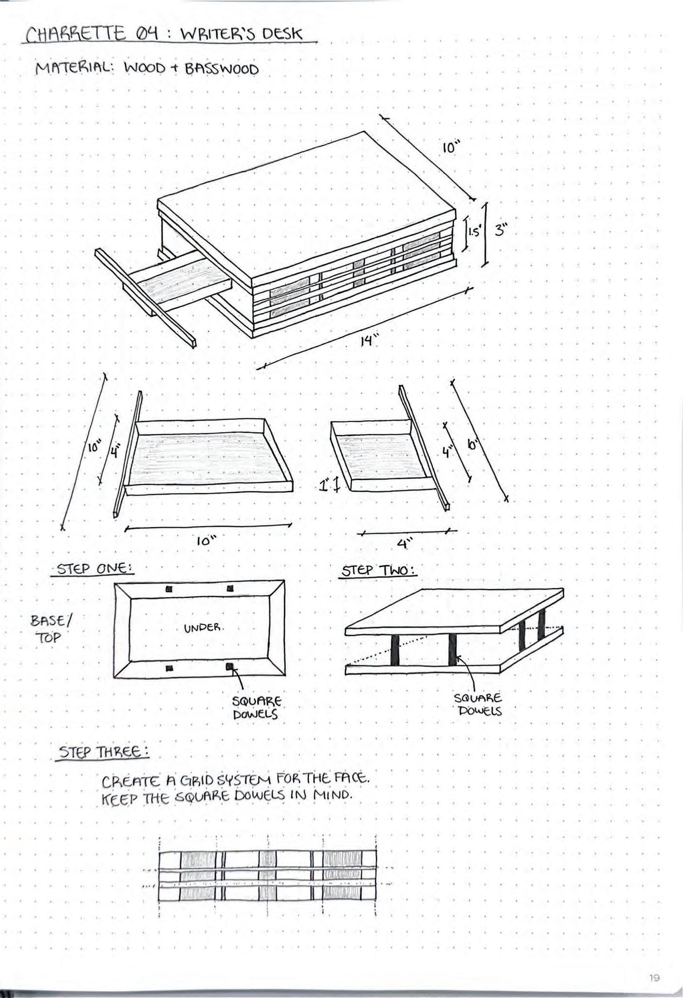
MATERIAL: Wood and Basswood
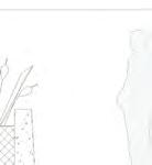
Using removable components to create a writer’s desk with a base, top, side walls, and a large and small drawer.
Dimensions: 10” x 14” x 3”
04: Prototype Model & Statement
Charette
Charrette 01 Drawings
02 Drawings
Charrette
Charrette 01 & 02
Drawings
Charrette 03 Drawings
Charrette 04 Drawings
Charrette 03 & 04
Drawings
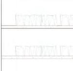
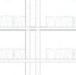
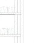
Reading Room
Charrette 05:
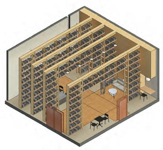
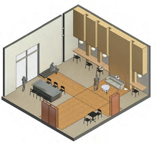
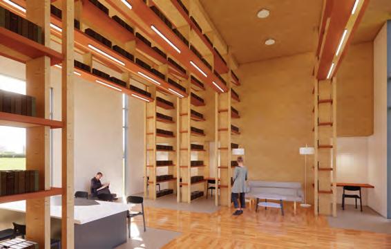
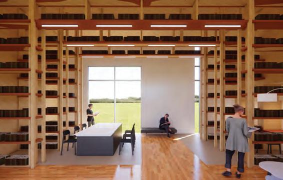
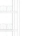
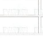
In this charrette, a reading room was to be designed by using the tectonic path chosen. In this reading room, the tectonic path was reflected onto the bookshelves with pieces that held together to support books on top. The placement of the bookshelf accommodates circulation and creates nooks for workspaces. These bookshelves were brought into the archive room and built within the structure as they are placed between the beams. Serving the same purpose of holding books, creating study nooks, and accommodating circulation.
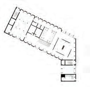
a. Floor Plan
b. Axon with Shelving
c. Axon without Shelving
d. Section of Bookshelf
e. Bookshelf Plan Detail
Charette 05: Reading Room Proposal
BUILDING PROPOSAL
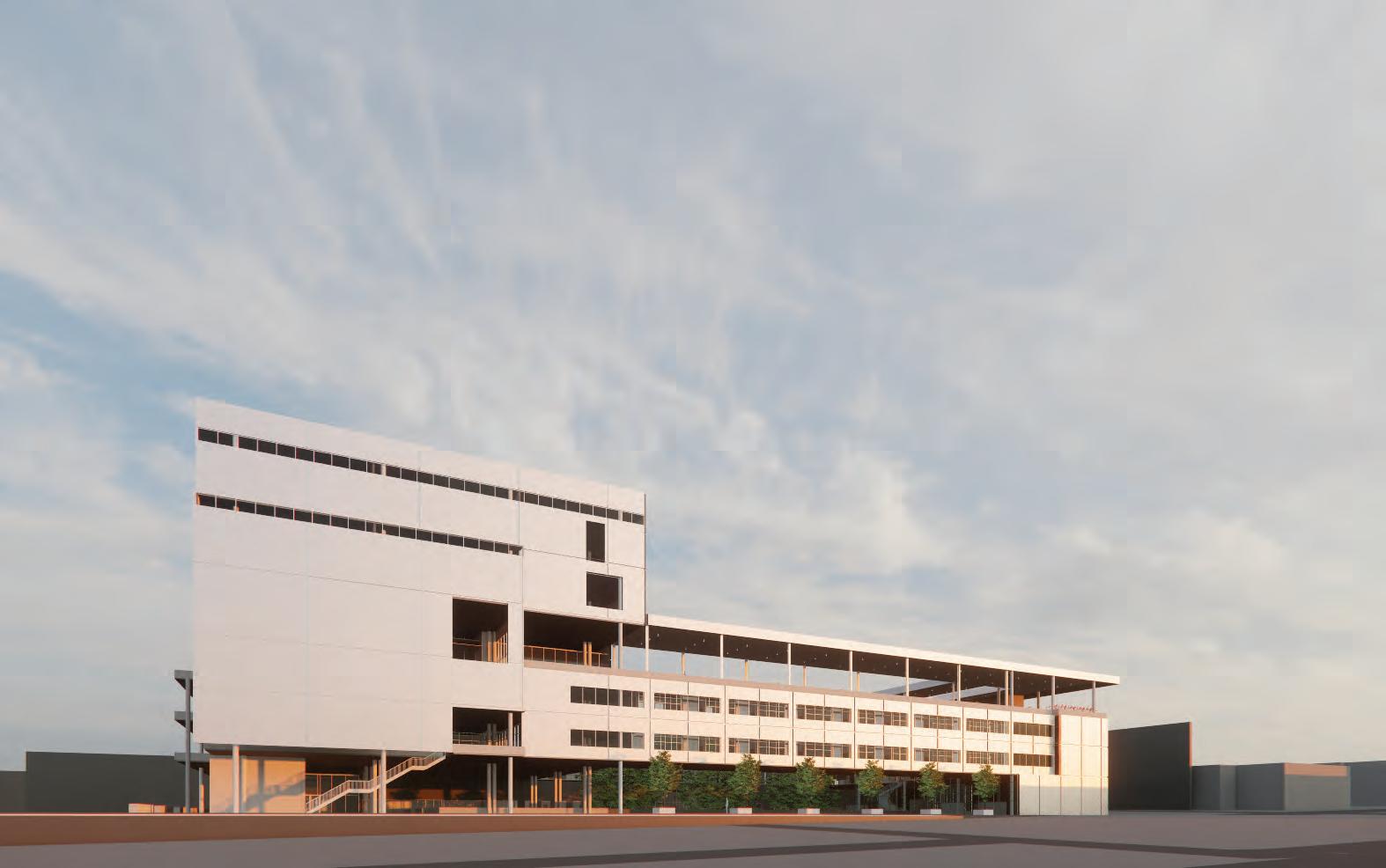
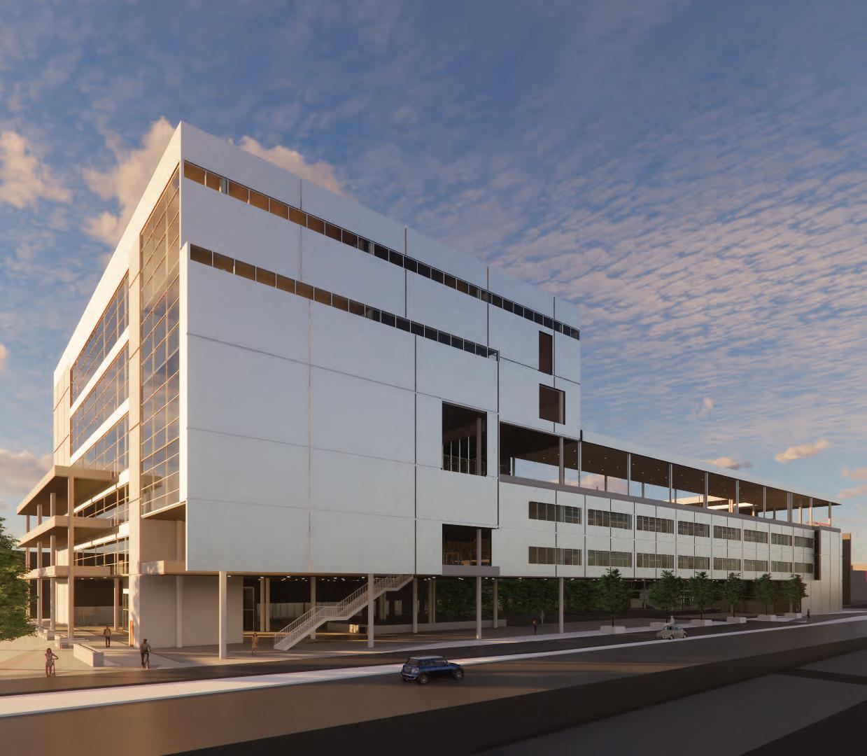
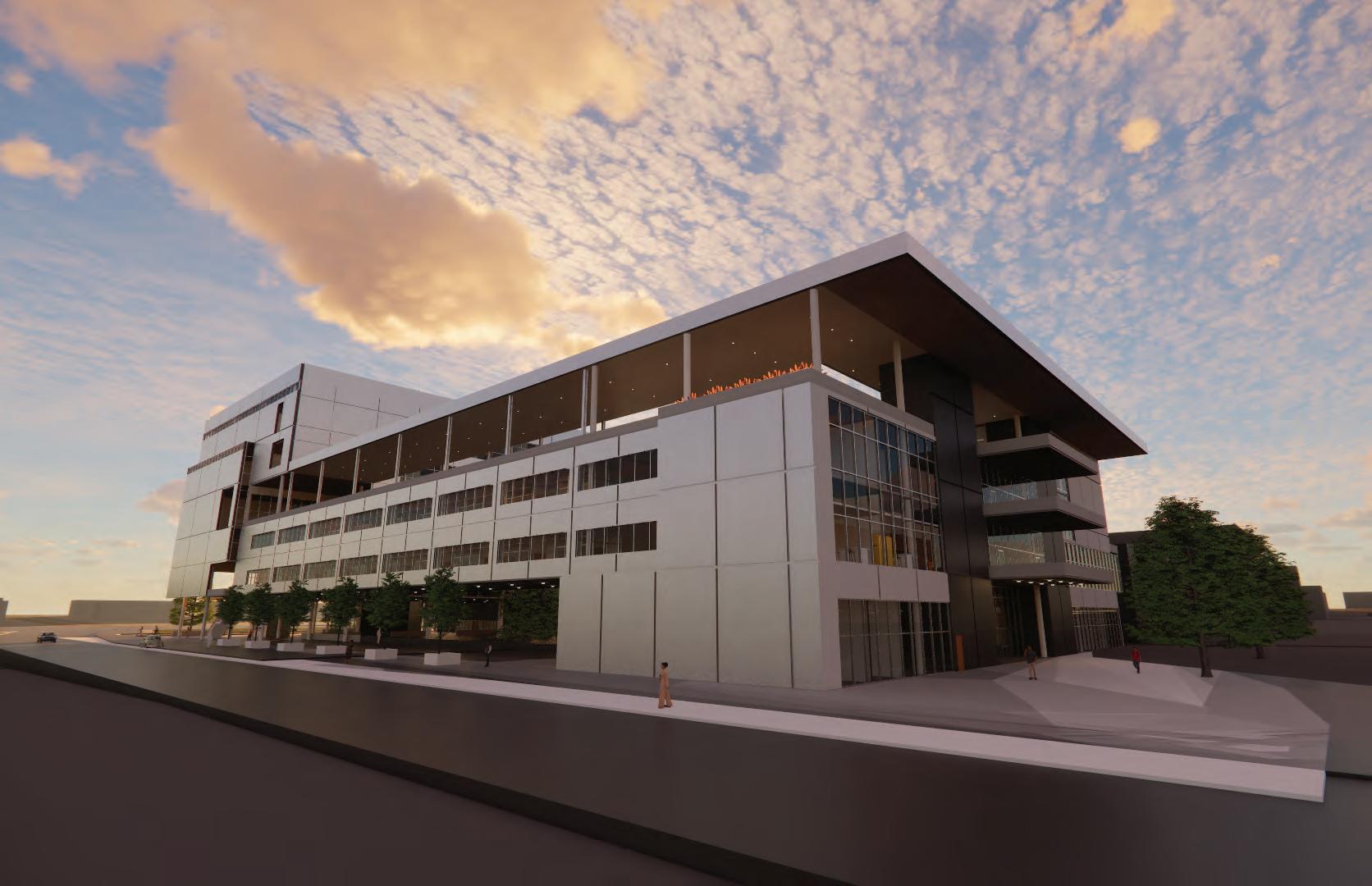
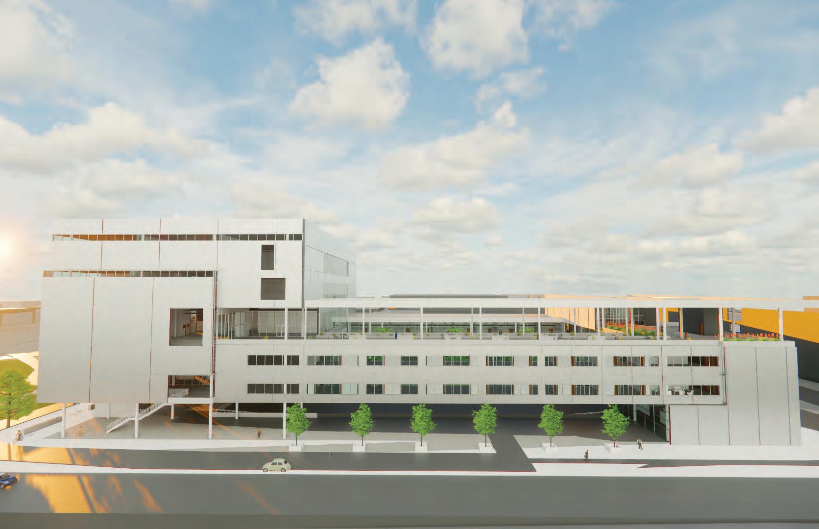
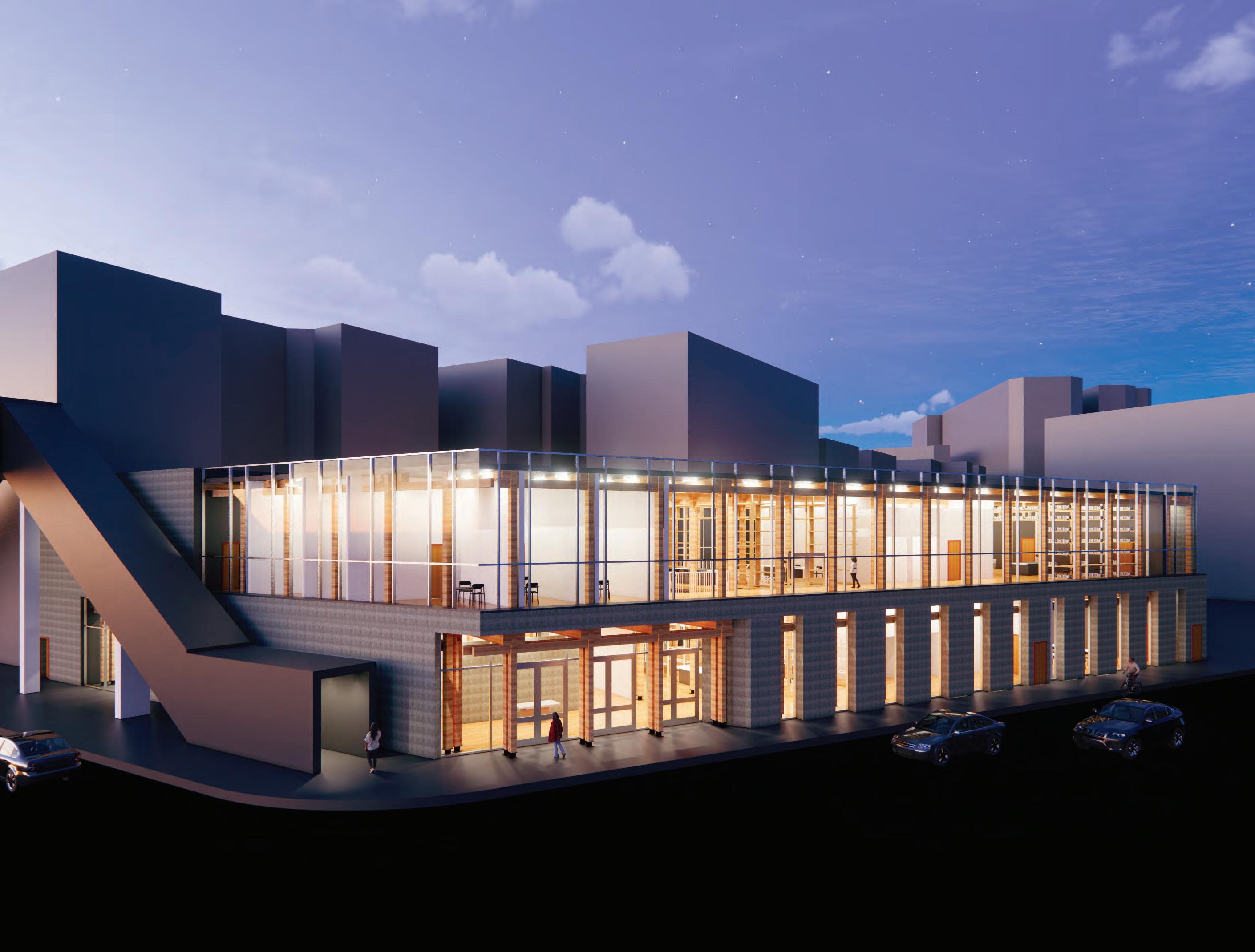
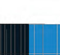
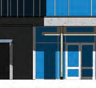
The Grant Archive building is an archive and reading room building for Columbia University at the Manhattanville Campus. The location was chosen on the corner of Broadway and W. 125th Street, to create a new beginning to the edge of campus. Its footprint is gained through the circulation created through the Forum Building, Jerome L. Greene Science Center, and the Lenfest Center. The campus holds Renzo Piano buildings that are concrete-heavy; therefore, the archive building holds a concrete feel on the outside to fit in with the campus while keeping its character inside through its timber structure. As you walk along the sidewalk, you’ll see thin window openings to give you a sneak peek of what’s inside.
Building Design Statement
Jane Grant: Singer / Writer / Feminist
With a heart for singing, Grant moved to New York where she took the journalistic route as she felt it was a more practical choice. There, she was the first woman journalist at the New York Times. She was a member of the Algonquin Round Table where she met her husband, Harold Ross. Together, they started their own magazine, The New Yorker.
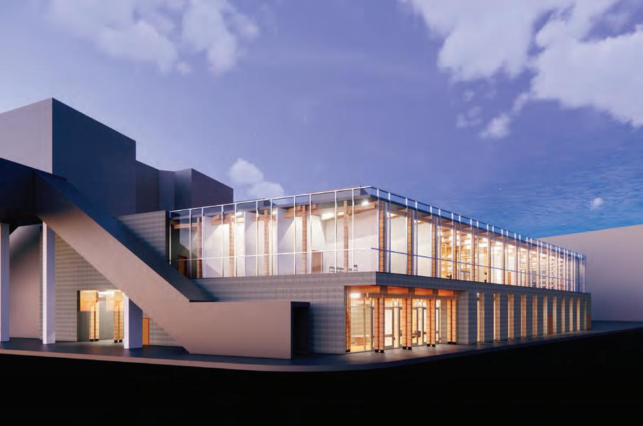
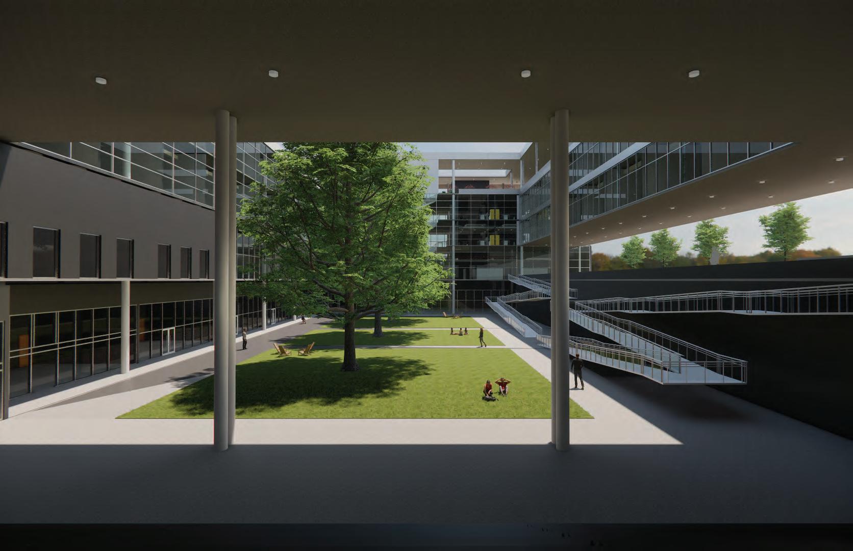
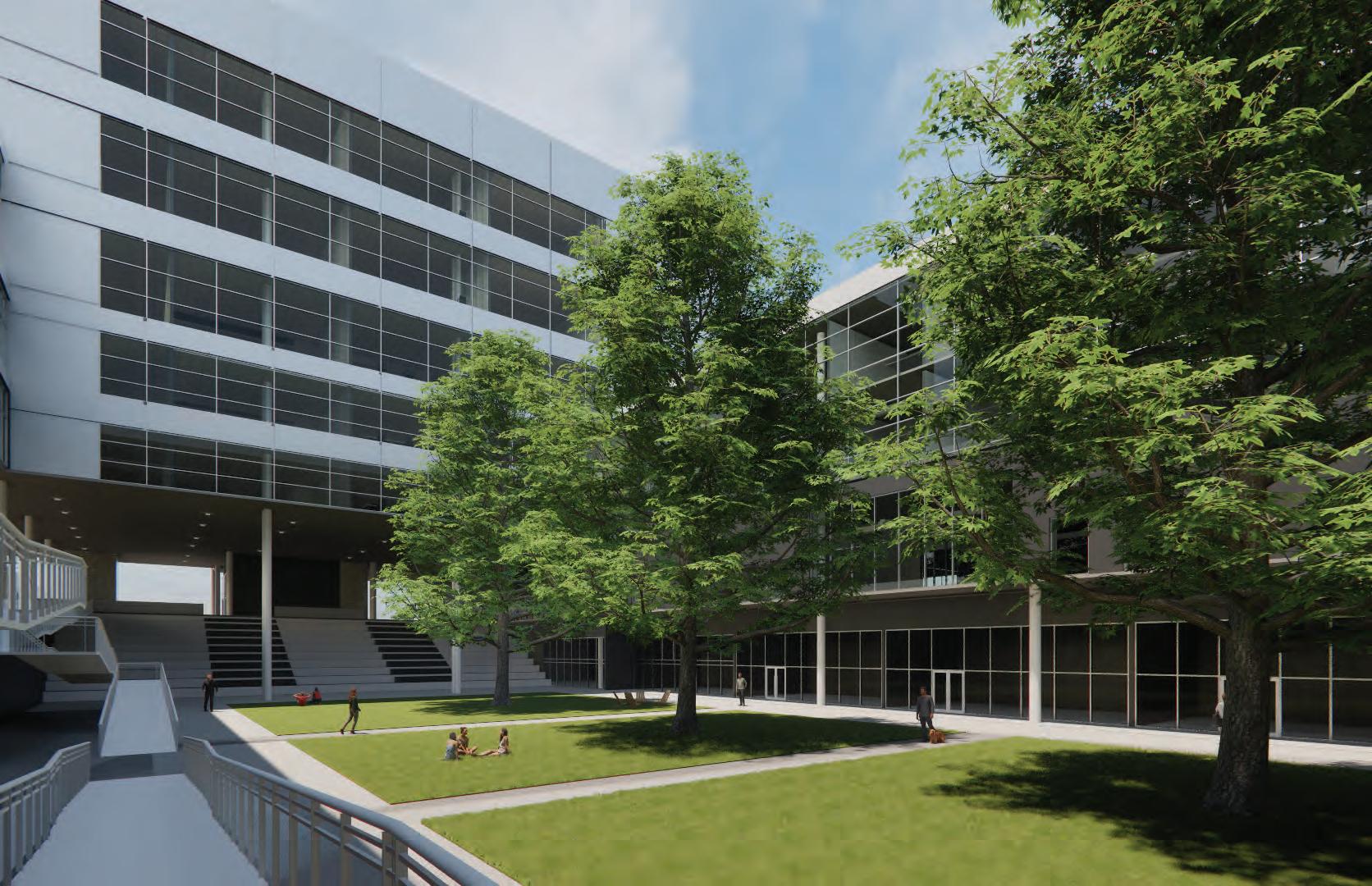
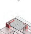
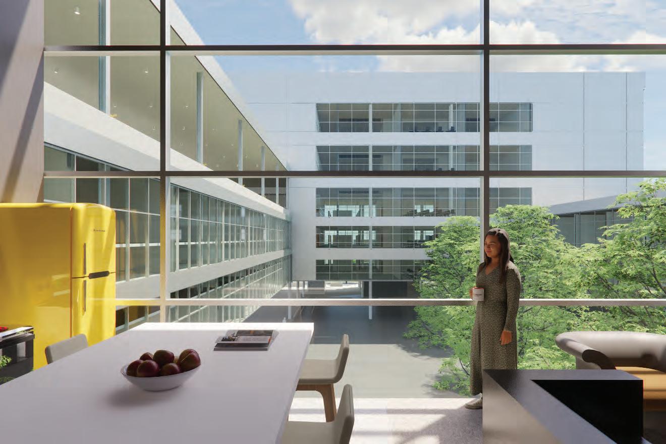
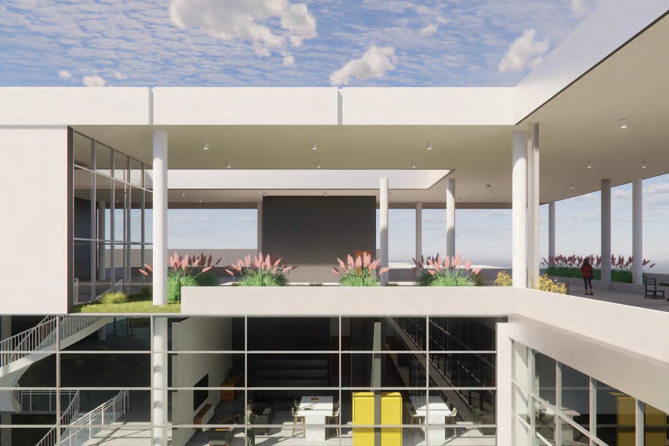
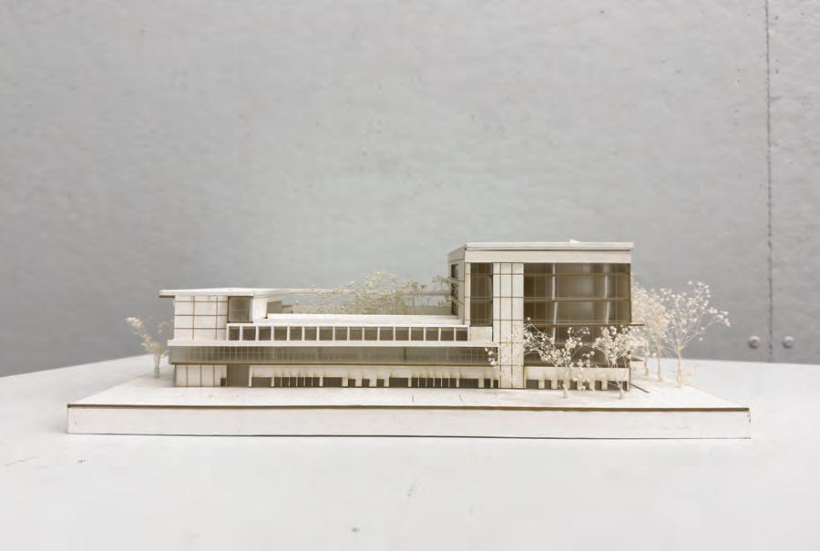
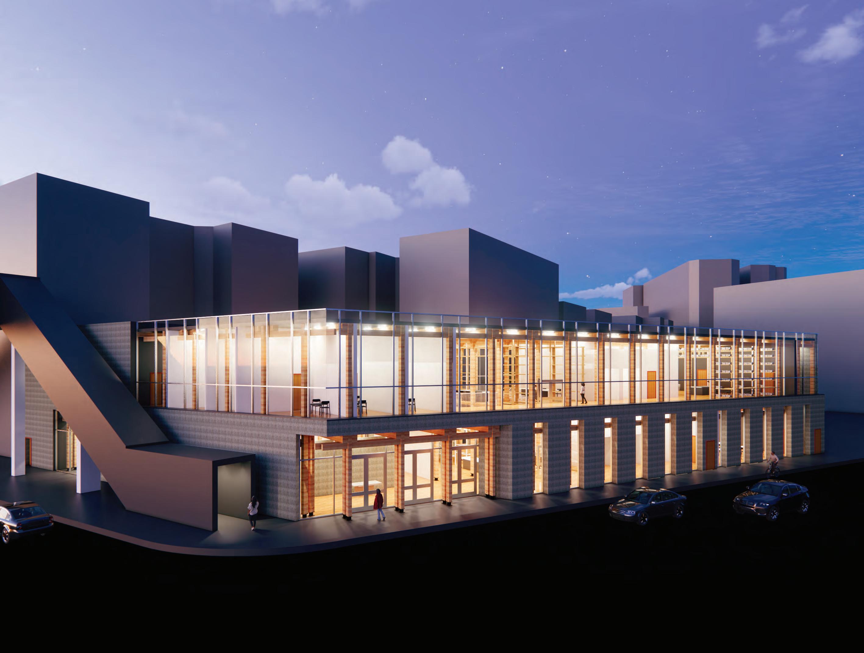
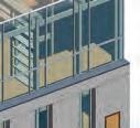
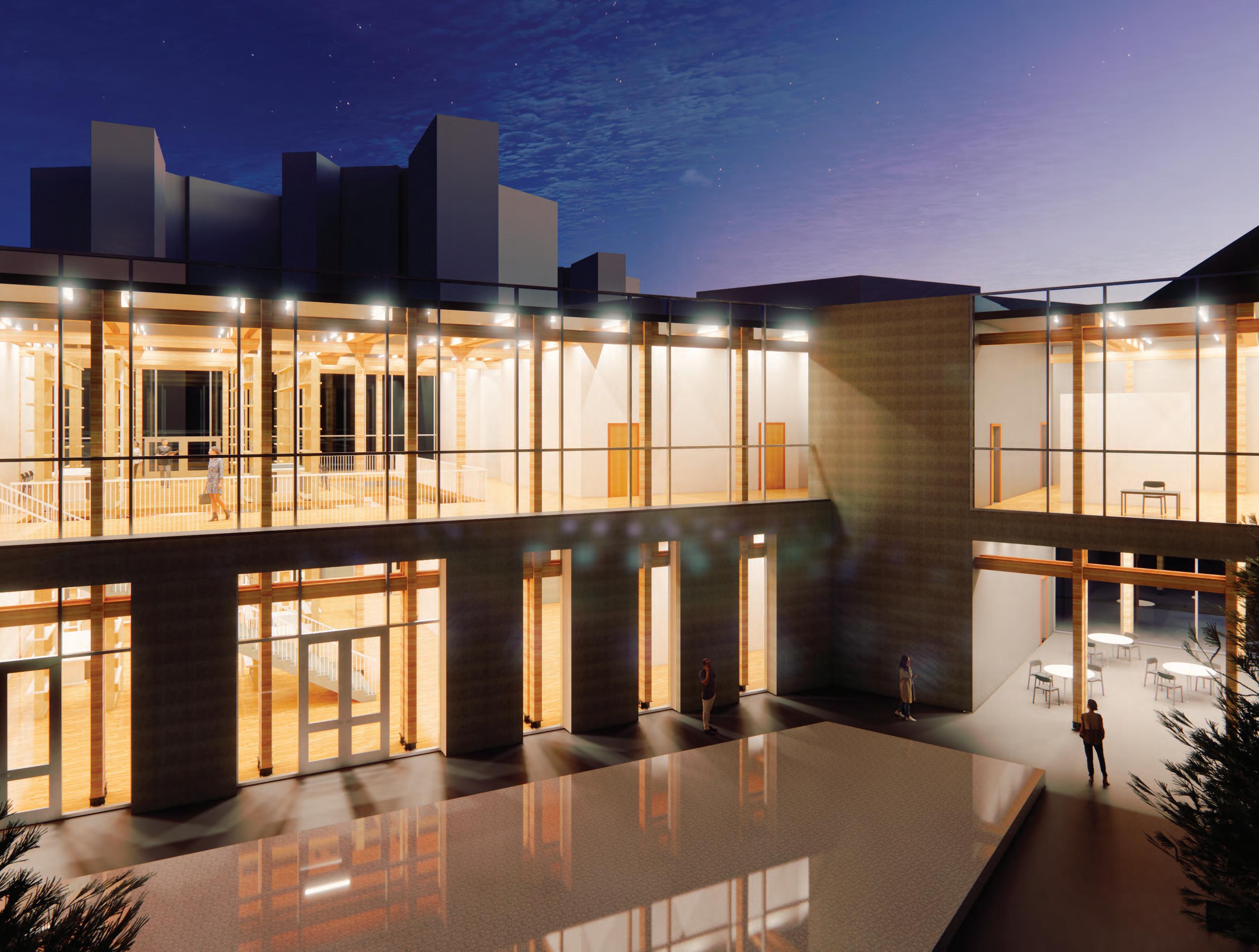
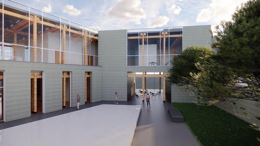
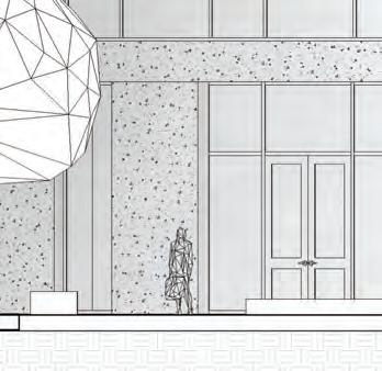
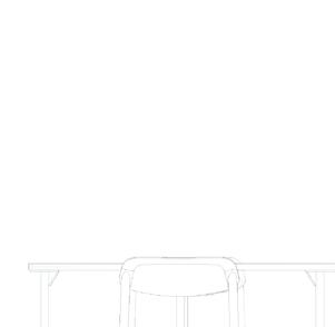
In the dedication of this building to Jane Grant, the archive and courtyard are created in her honor. The archive represents the heart of the building and the legacy that Jane Grant holds. In the courtyard, you will find an informal stage that can be used for gatherings. This stage is in honor of her performing side and represents her love for singing. In total the building shows how she has multiple passions, inside and outside.
Building Dedication
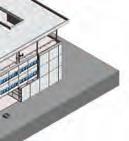
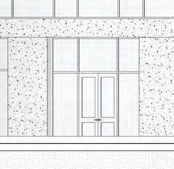
c.
Axon. of Section Courtyard View Reading Room
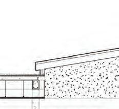
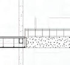
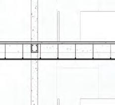
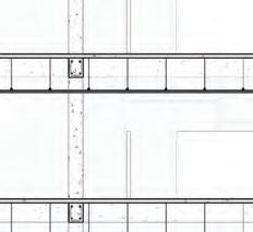
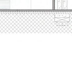
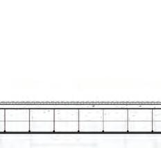
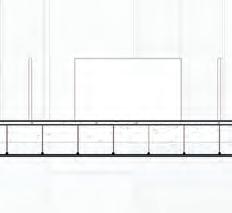
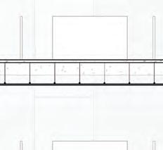
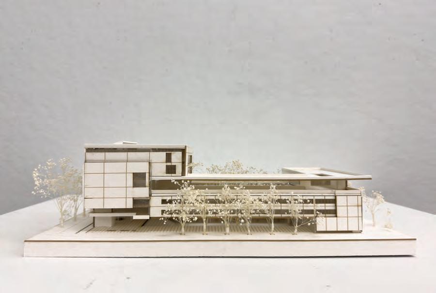
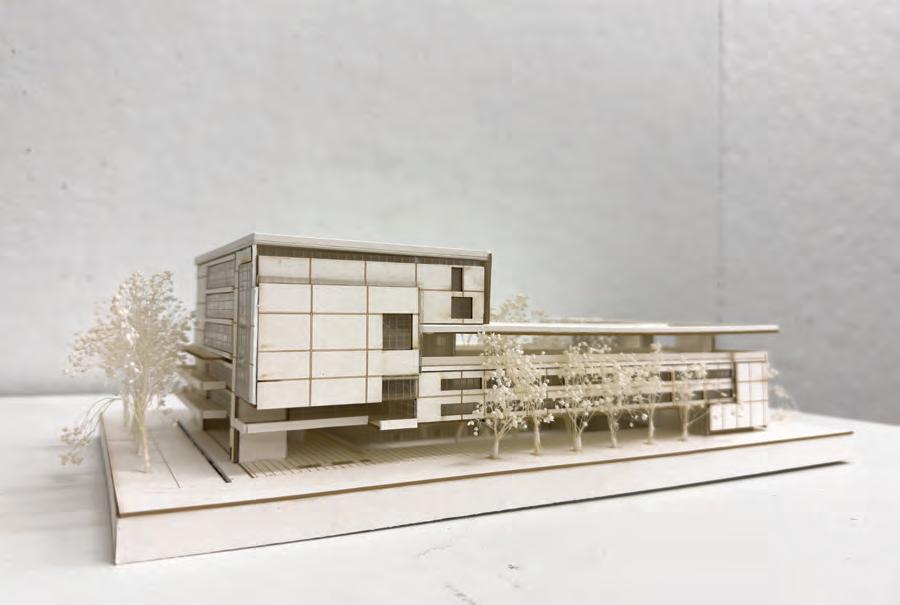
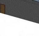
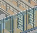
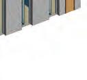
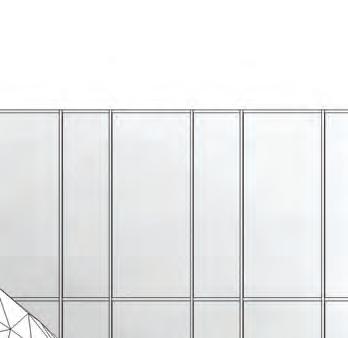
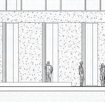
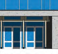
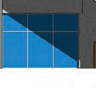
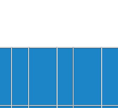
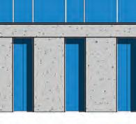
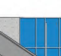
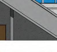
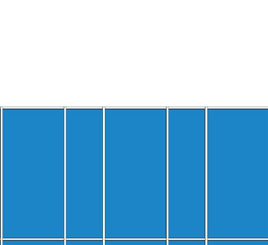
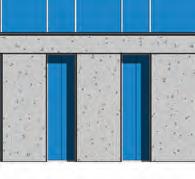
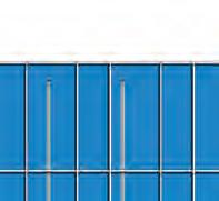
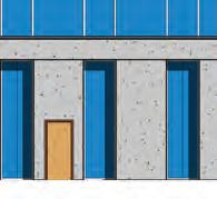
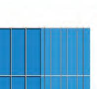
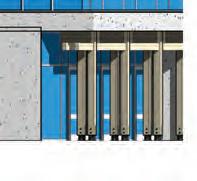
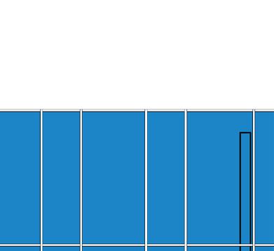
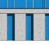
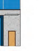
Exterior Walls from Street a. b. c. d.
Additional Building Images
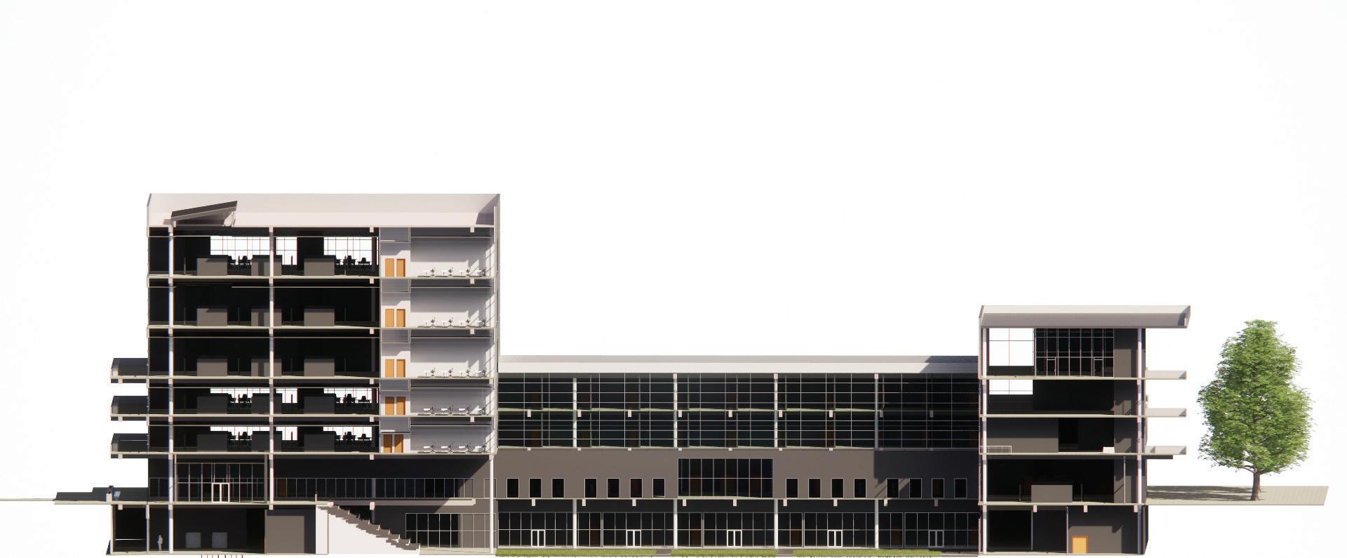
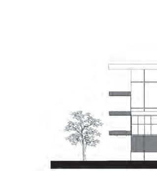
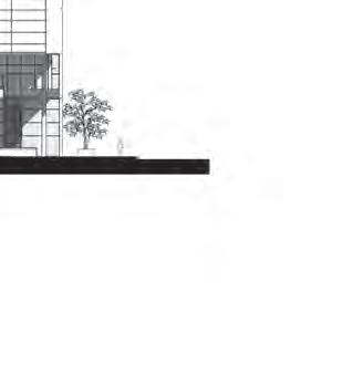
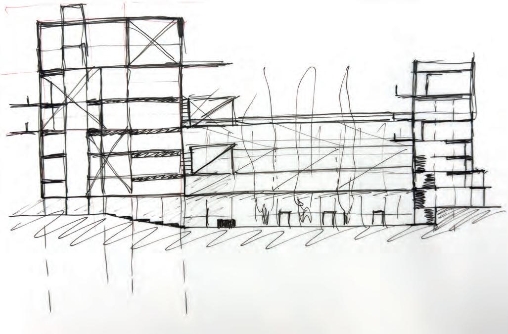
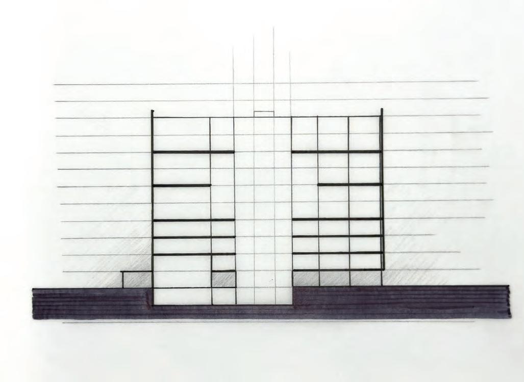
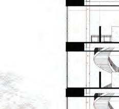
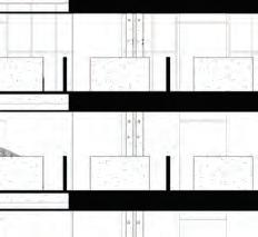
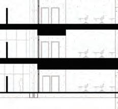
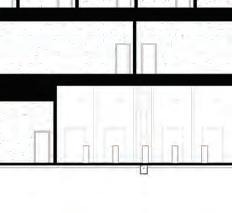
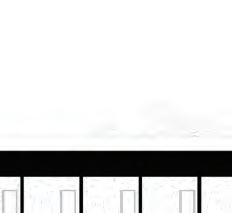
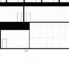
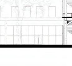
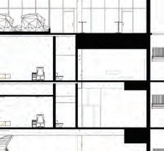
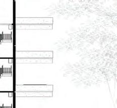
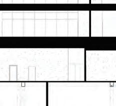
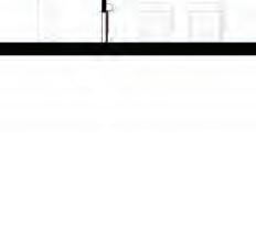
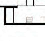
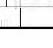
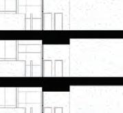
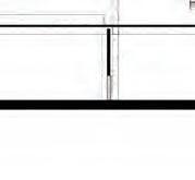
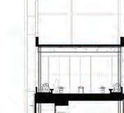
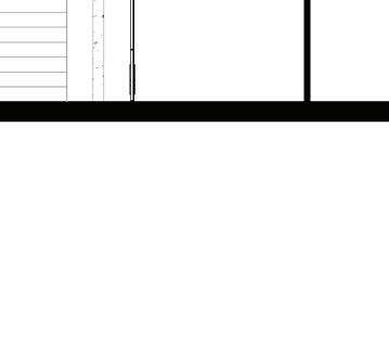
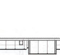
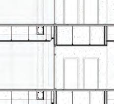
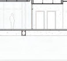
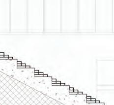
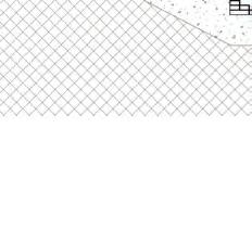
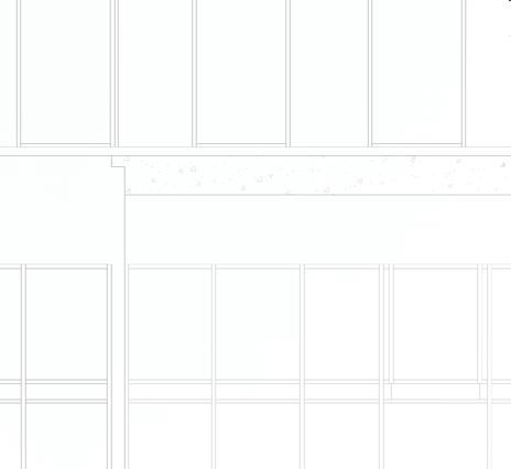
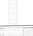
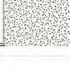
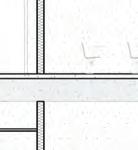
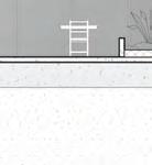
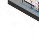
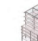
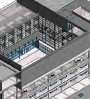
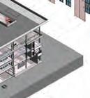
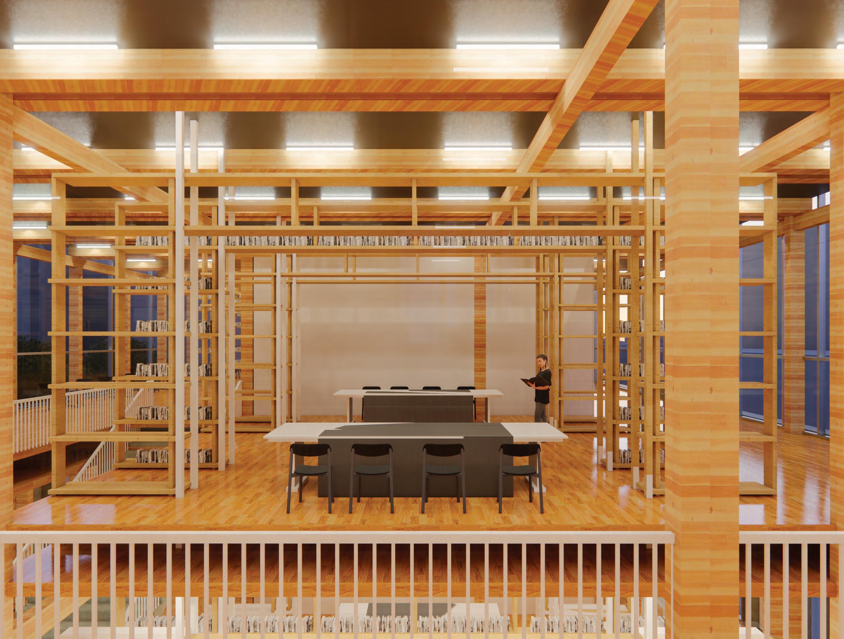
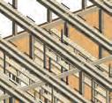
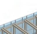
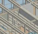
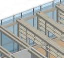
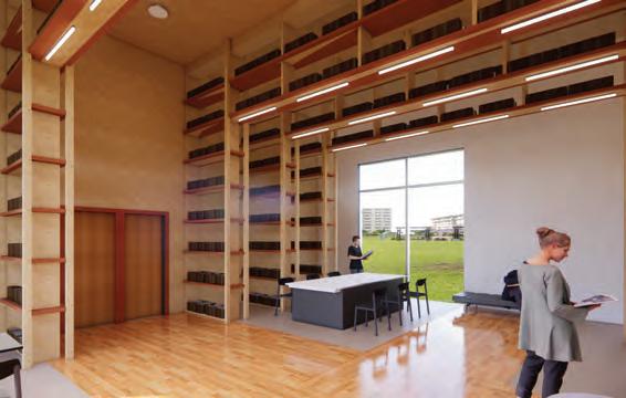
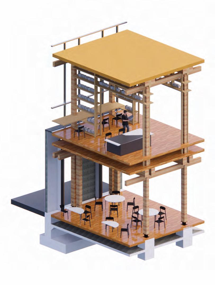
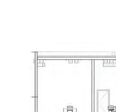
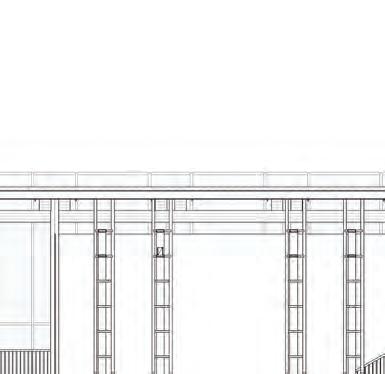
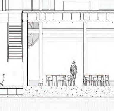
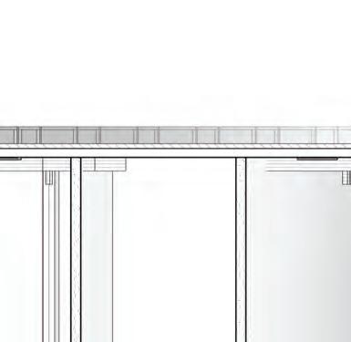
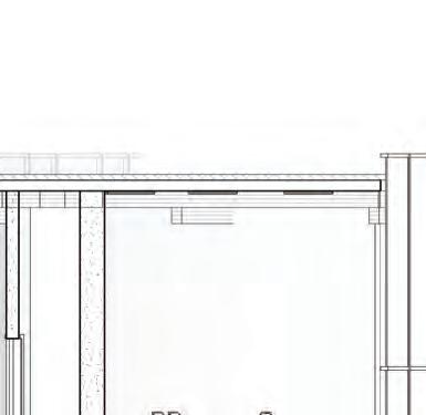
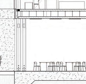
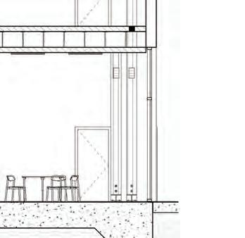
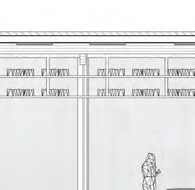
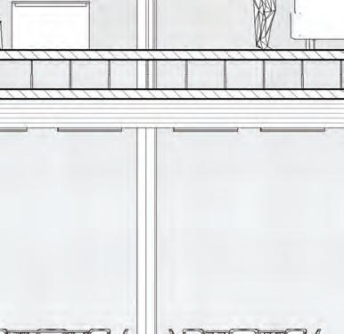
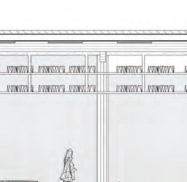
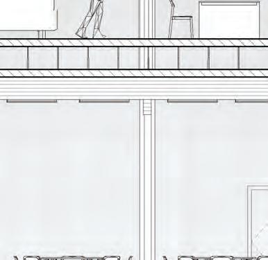
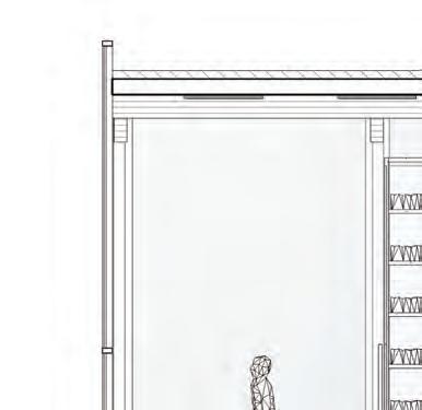
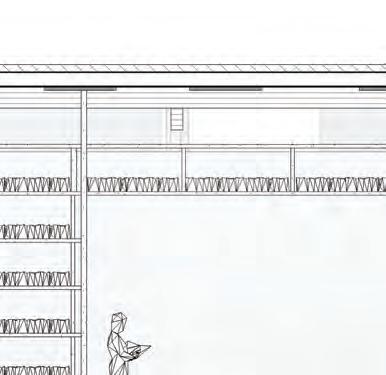
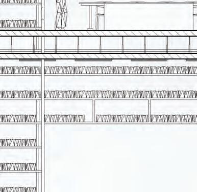
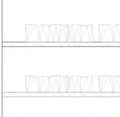
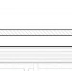
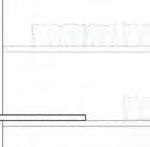
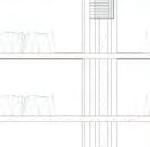
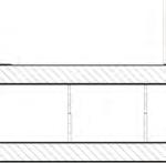
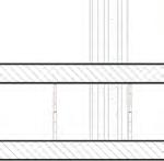
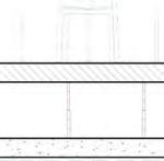
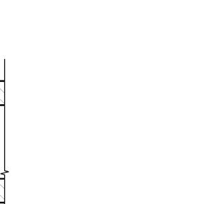
This section shows the timber structure that holds up the building and shows the lecture room on the first level and the reading room on the second level.
Additional Building Images & Diagrams
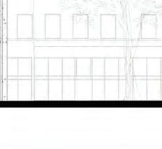
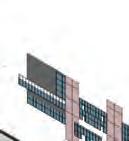
Building Concept
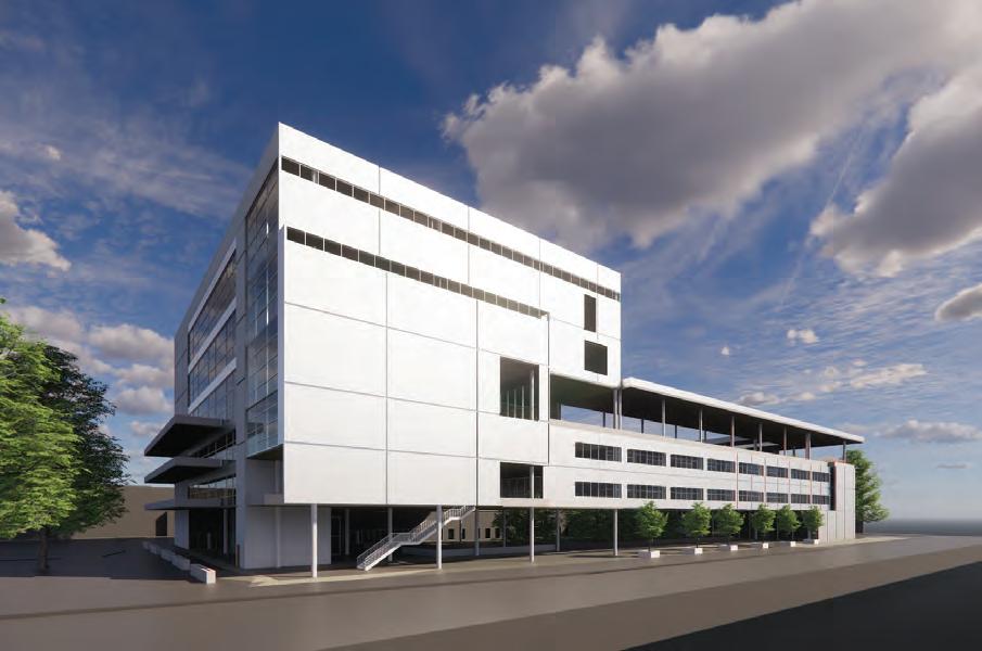
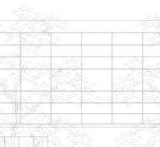
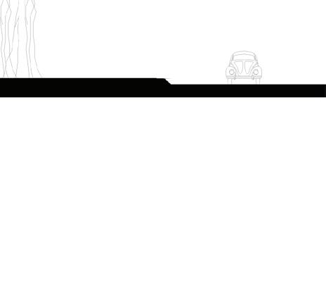
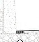
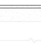
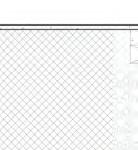
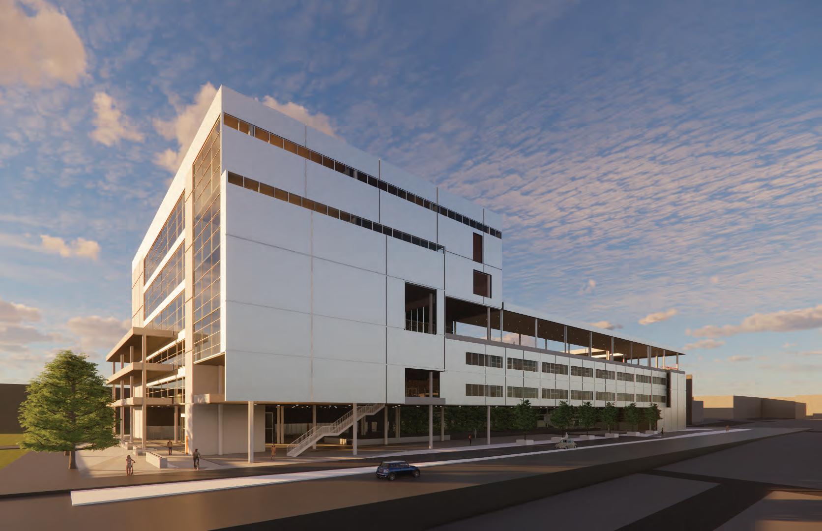
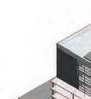
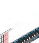
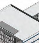
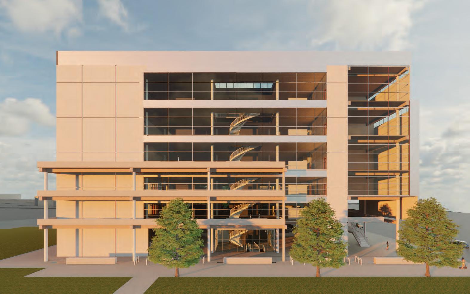
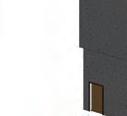
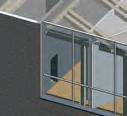
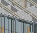
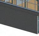
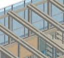
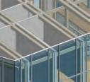
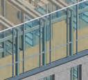
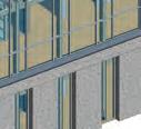
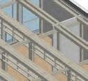
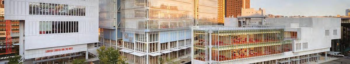
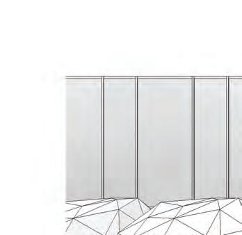
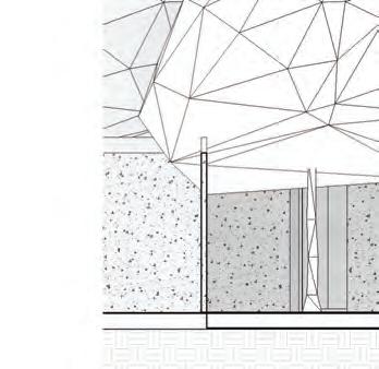
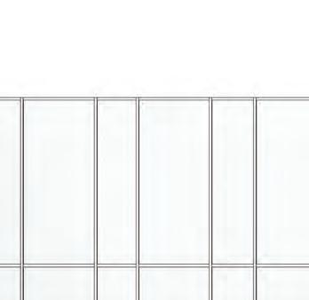
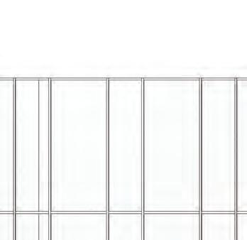
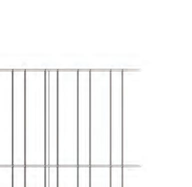
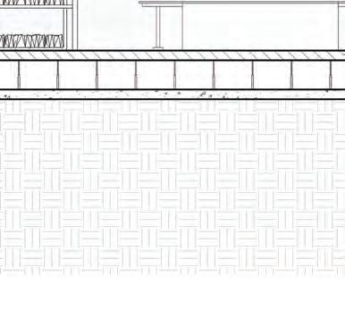
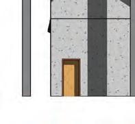
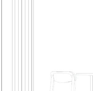
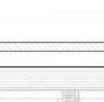
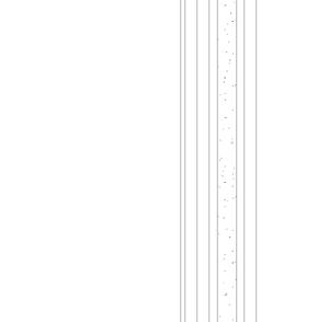
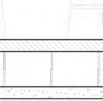
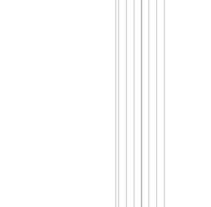
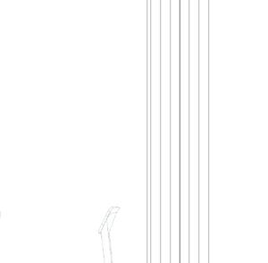
With Columbia University Manhattanville Campus being mainly concrete and glass heavy, the Grant Archive contributes to campus through its choices of exterior materials. As pedestrians walk along the sidewalk, they will experience the heavy base of the building, followed by a light tall curtain wall that appears to exceed the roof and feel neverending. This helps with the size of the building to fit in with the taller structures on campus. As pedestrians look through the nooks of glass, they will be exposed to the interior timber structure that holds the building’s individuality.
Image from below from: https:// neighbors.columbia.edu/content/ explore-campus
Building Concept
Building Program & Tabulation Diagrams
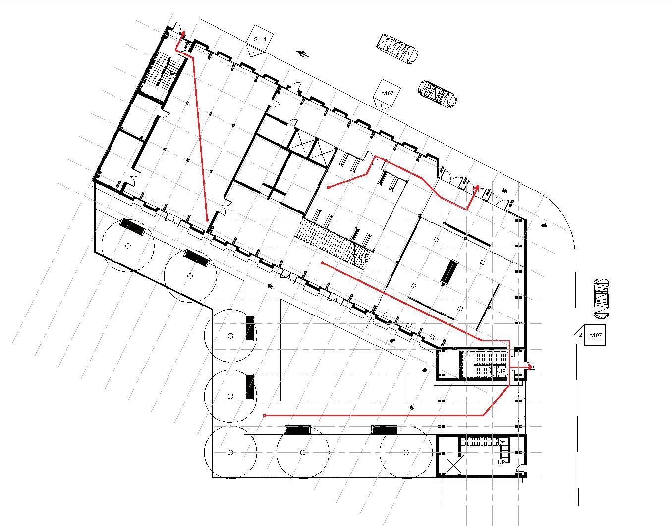
The site circulation took into consideration the direction of the streets and the entrance of the train in relation to the building. The main circulation that was considered is the connection between The Forum’s entrance to the Grant Archive entrance across 125th Street.
Site Circulation &
Site Opportunities Diagram
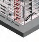
Building Circulation & Egress Diagrams
Design Study 01
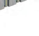
This structural connection was created by gluing the pieces together. This was one of the initial conditions that begin to teach one how a self-supported condition could be created by constructing the connection and learning from its creation.
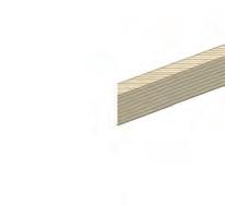
Design Study 02
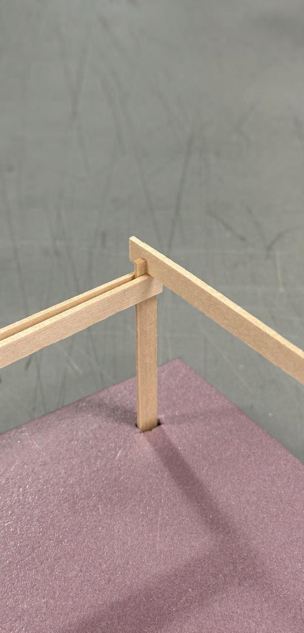
This structural design introduced the idea of using slits at the top of the columns to support a beam on top. The issue that this brought up was that the bottom piece was not supported solely on the condition but would need adhesion instead.
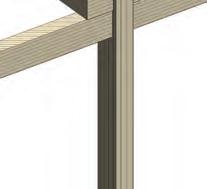
Design Study 03
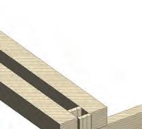
This study focused on similar elements from Design Study 02 to explore the connection being used at a corner. This helped further explore the idea of a self-supporting connection to function under multiple conditions.
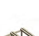
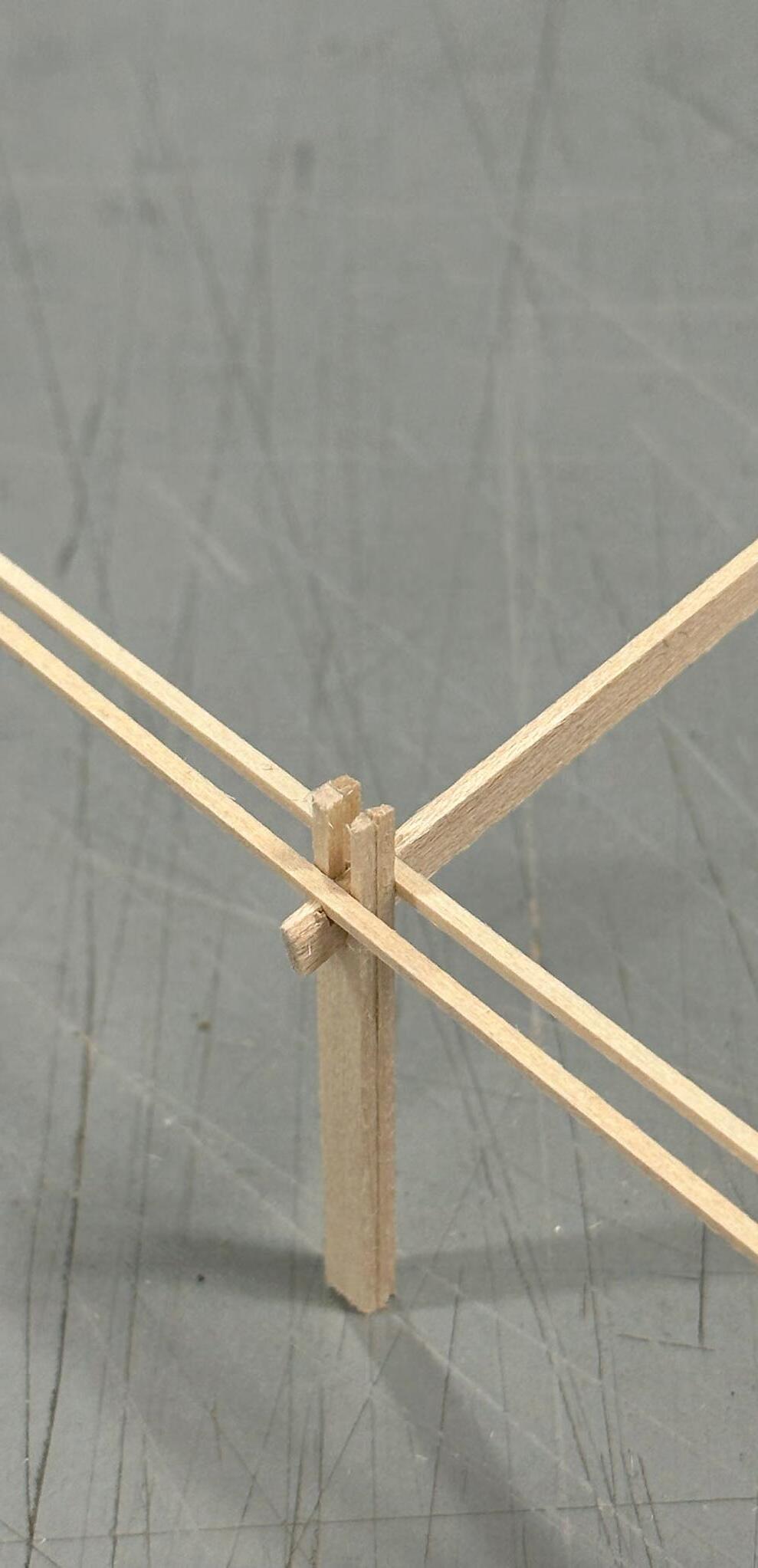
Design 04
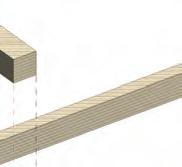
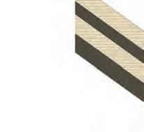
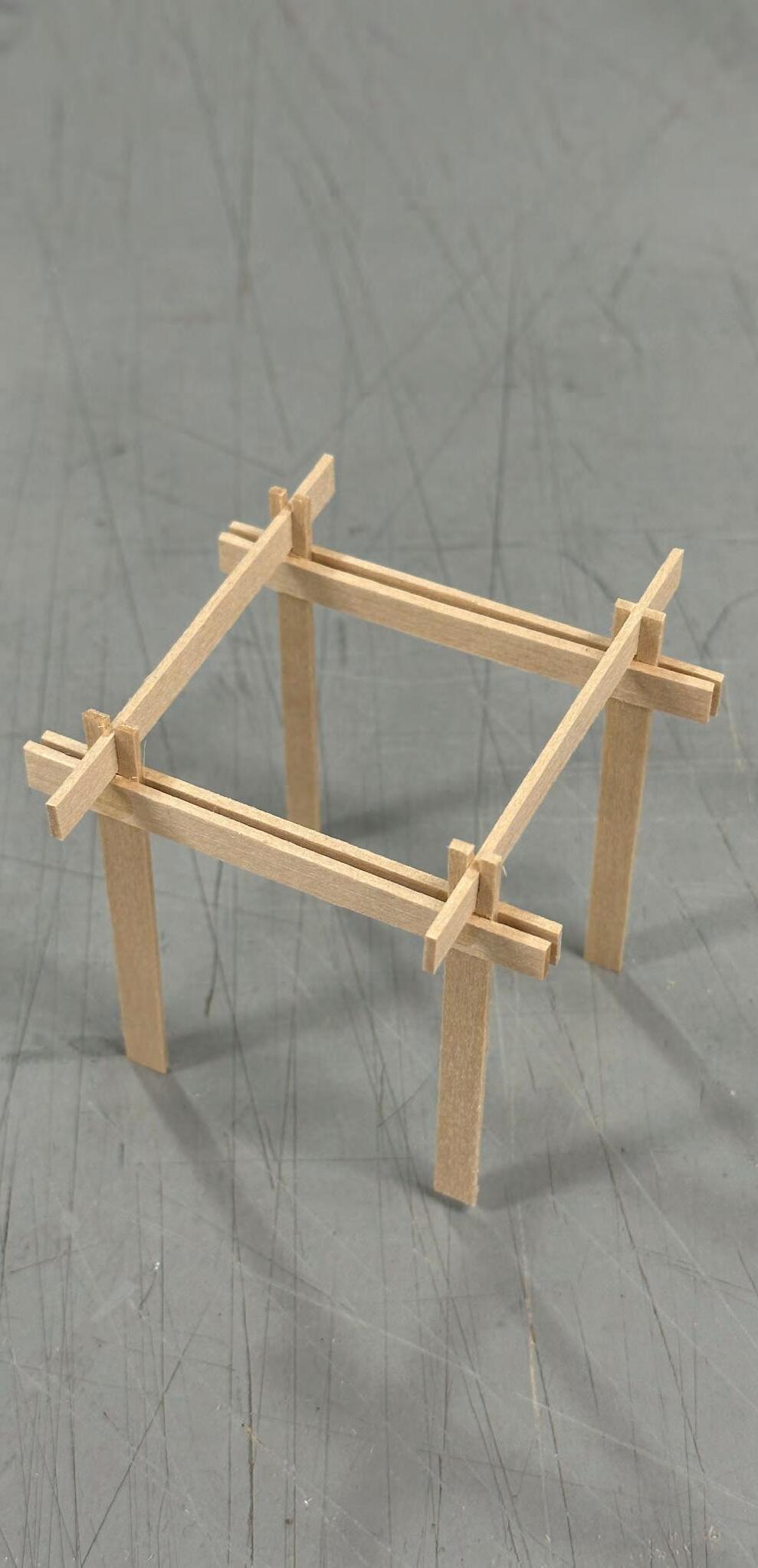
This connection study showed success in a self-supporting condition. First, the beam goes through the slit of the column. Next, the beam has two slits, on each side of the column, where a thin girder is placed on each side, creating the condition to lock in place altogether. The next challenge to explore is the thickness of each piece.
Before the final design of the structural connection, design studies were created to begin the curiosity of a self-supporting piece. Creating these study pieces helped teach structure and support through the construction of each.
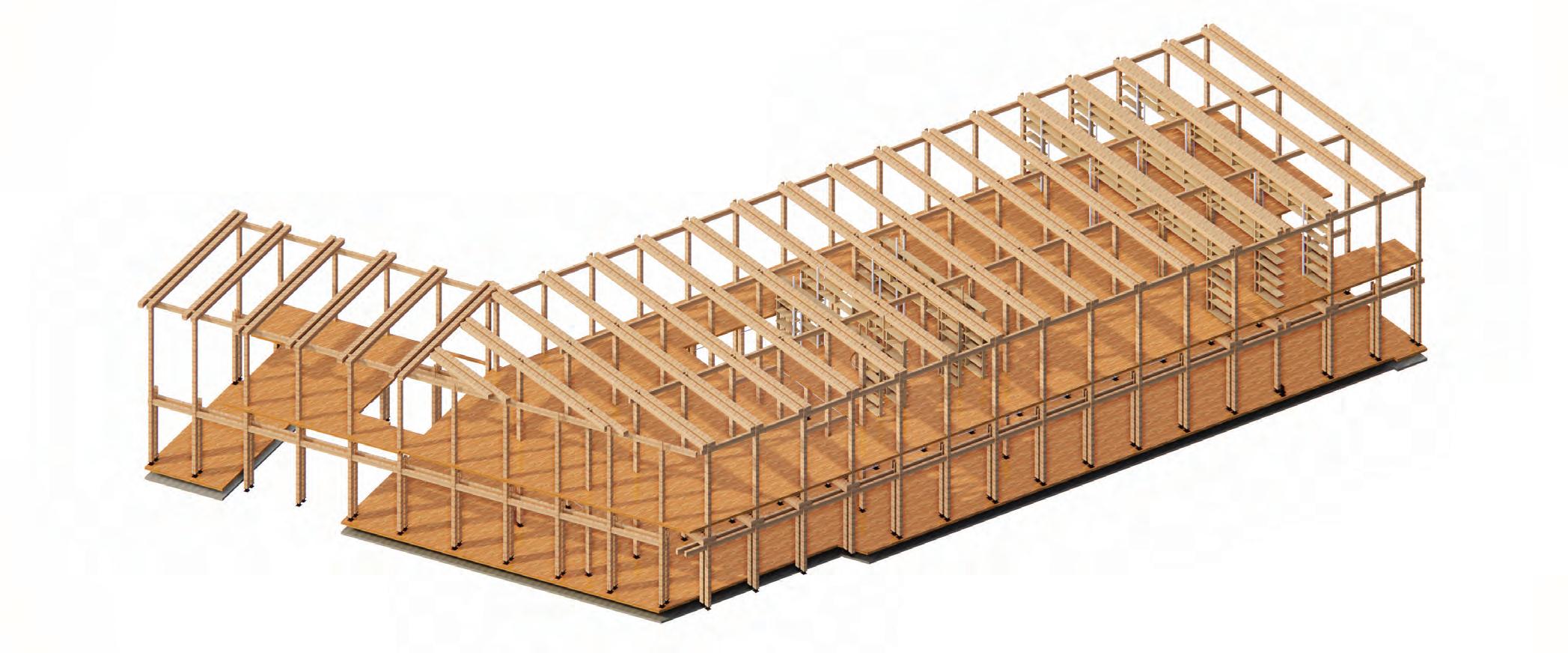
Initial Building
Framing/Structural Diagrams
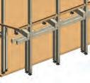
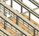
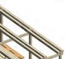
From the charrettes challenges, the final tectonic design focused on the structural connection throughout the building. The connection was designed with components that are leaning on one another in order to maintain a joinery with rigidity and strength to withstand dead, live, and lateral loads within the building.
Final Building
Framing/Structural Diagrams
Final Structural Connection Design Undone Connection
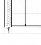
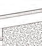
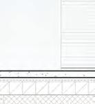
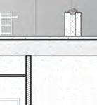
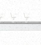
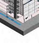
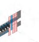
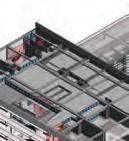
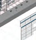
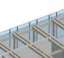
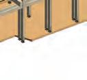
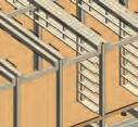
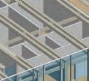
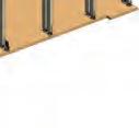
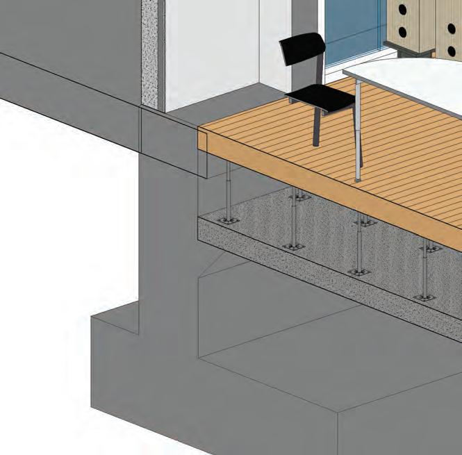
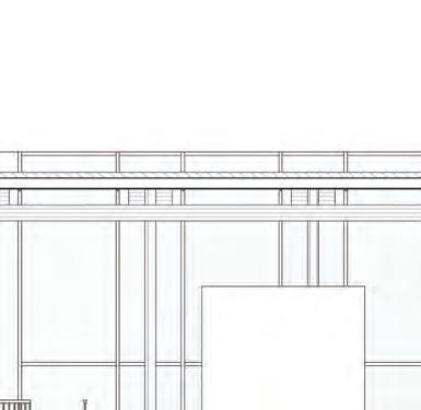
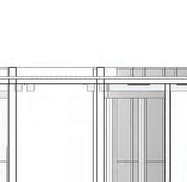
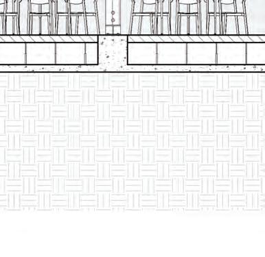
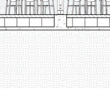
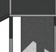
The raised floor system is used on both levels of the building to provide a hidden void between the slab and floor system to provide space for mechanical and electrical services. This approach was adopted in order to allow the building to show its structure instead of concealing it in a dropped ceiling system. This system will allow maintenance by accessing systems by lifting a panel. Towards the exterior, air vents are placed so that heat or air conditioning can circulate from below and into the space. This will help keep the building warm as the air will push along the exterior walls or glass, preventing heat loss to pass through. This will help create a consistent temperature throughout the rooms.
Building
Environmental System Diagrams
Upper
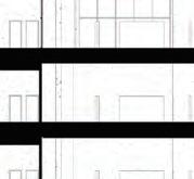
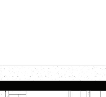
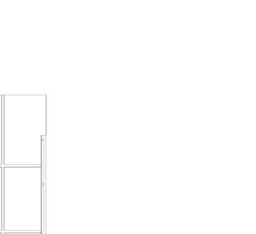
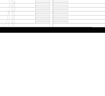
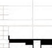
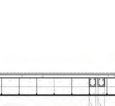
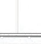
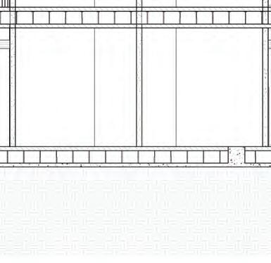
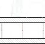
A. LONGITUDINAL SECTION
Building Longitudinal Section
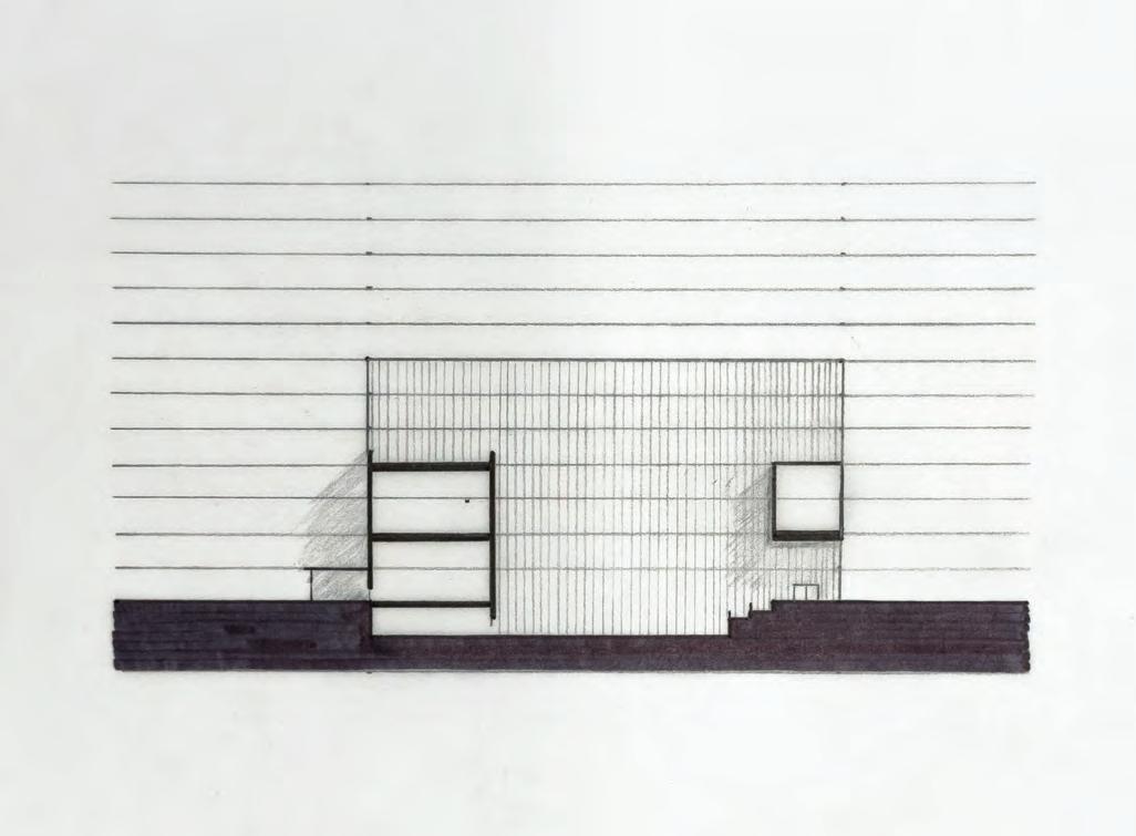
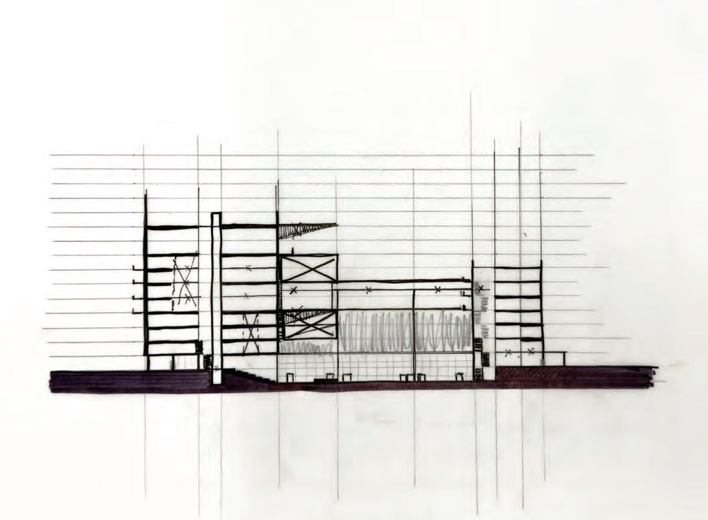
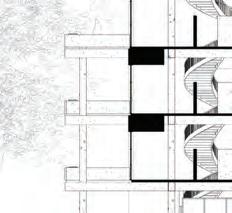
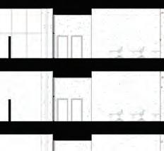
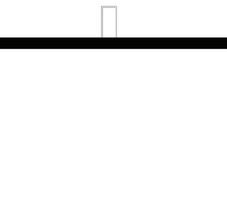
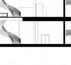
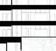
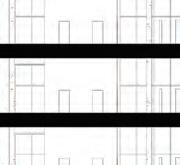
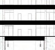
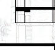
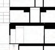
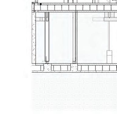
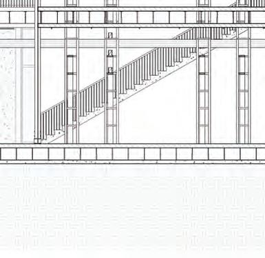
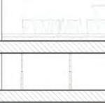
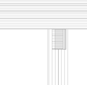
Building Transverse Sections
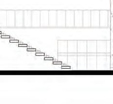
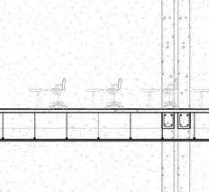
D. TRANSVERSE SECTION - READING ROOM & LECTURE ROOM
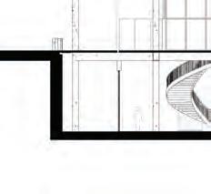
Reading Room Section
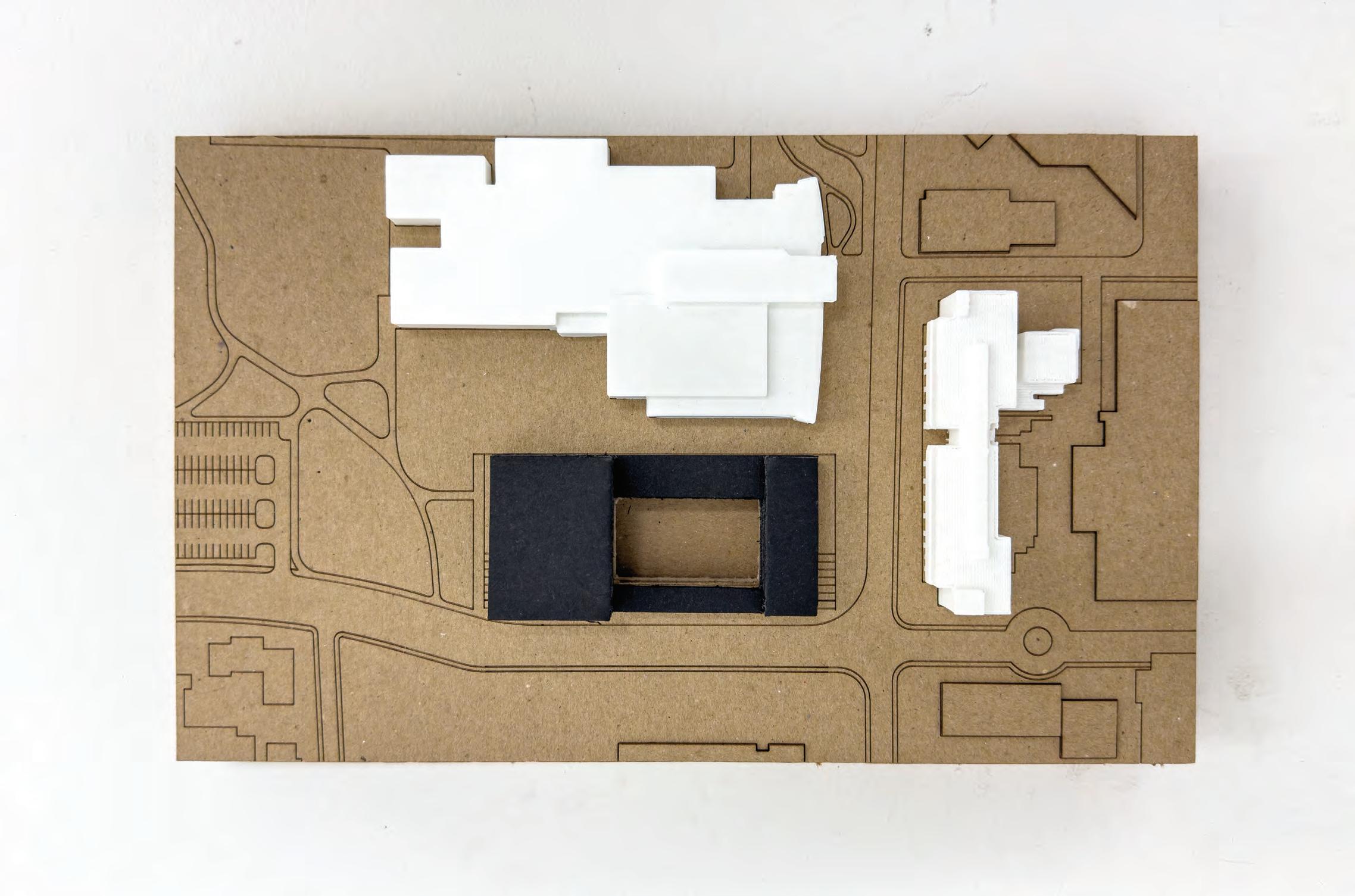
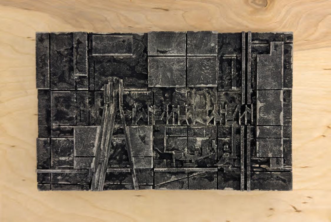
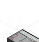
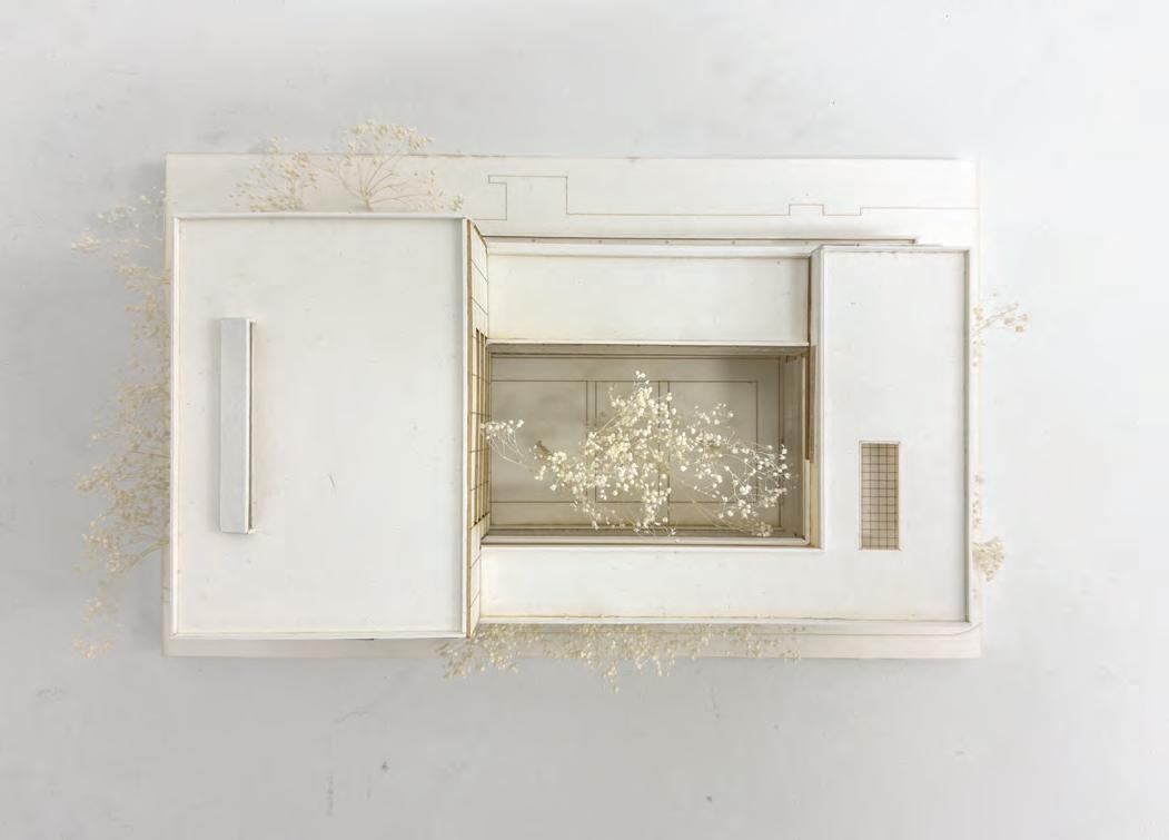
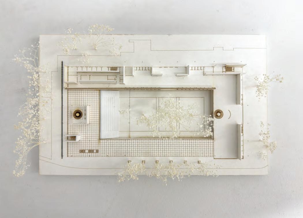
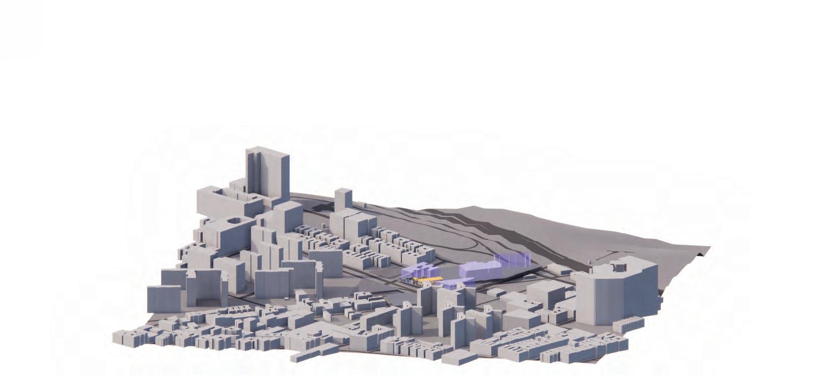
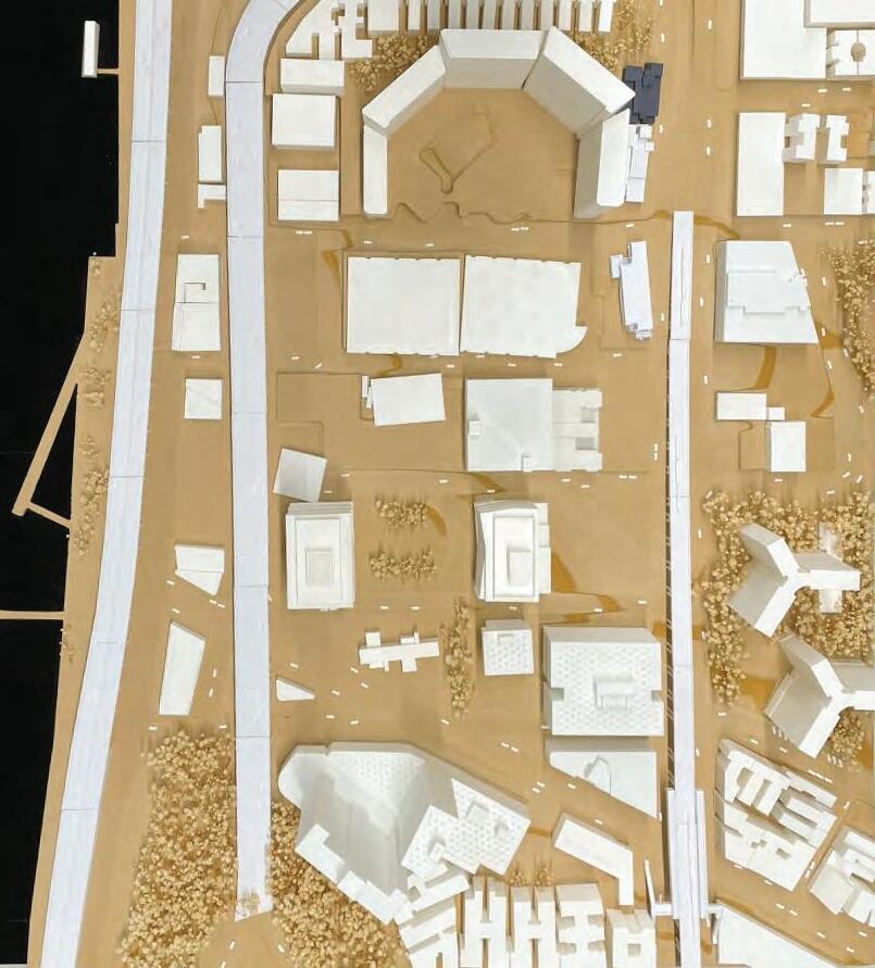
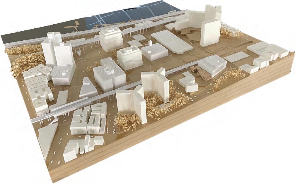
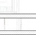
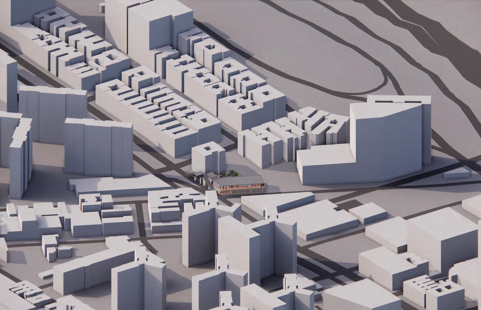
The site model of Columbia University / Manhattanville Campus was created by the entire class to show existing buildings, roads, highways, viaducts, and topography. Each student created a model of their building to place on the site model. In the image to the left, you will see the model facing New York North. The Grant Archive is located on W. 125th St. and Broadway and is shown in the red dashed line on the image.
Site Model photographs
Physical
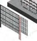
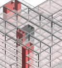
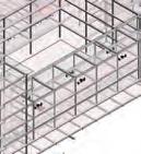
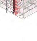
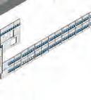
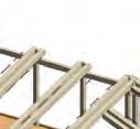
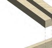
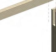
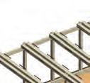
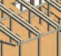
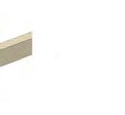
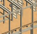
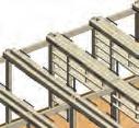
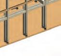
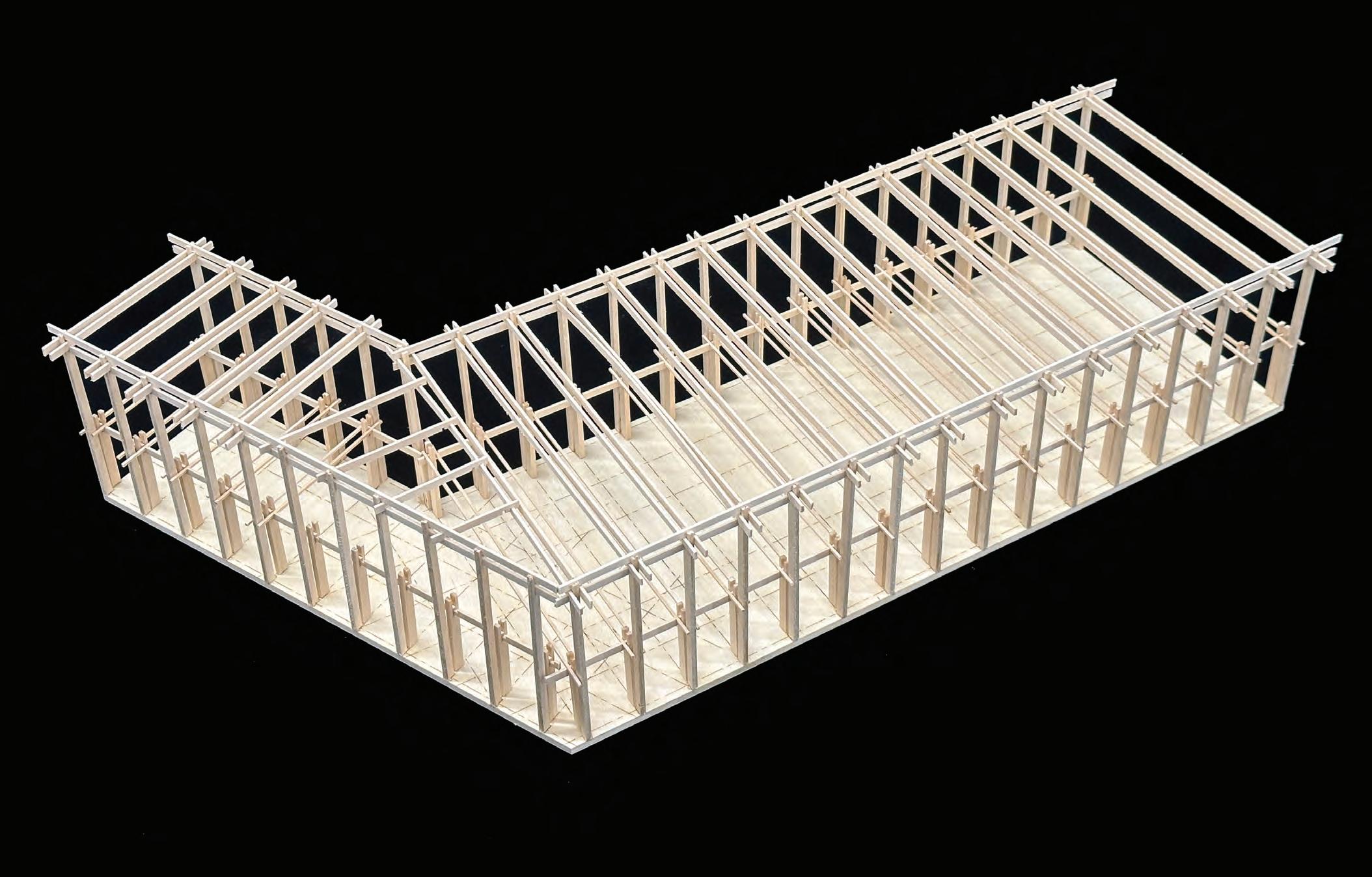
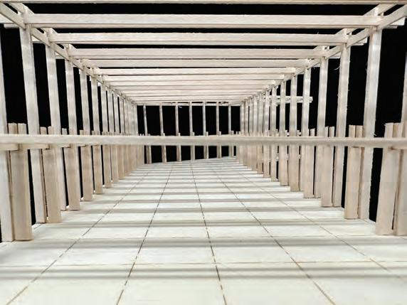
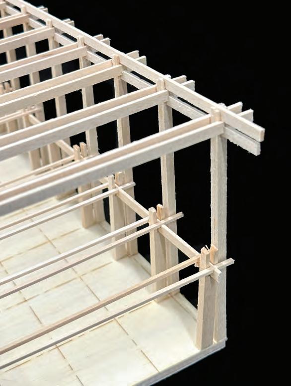
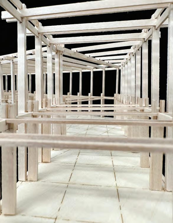
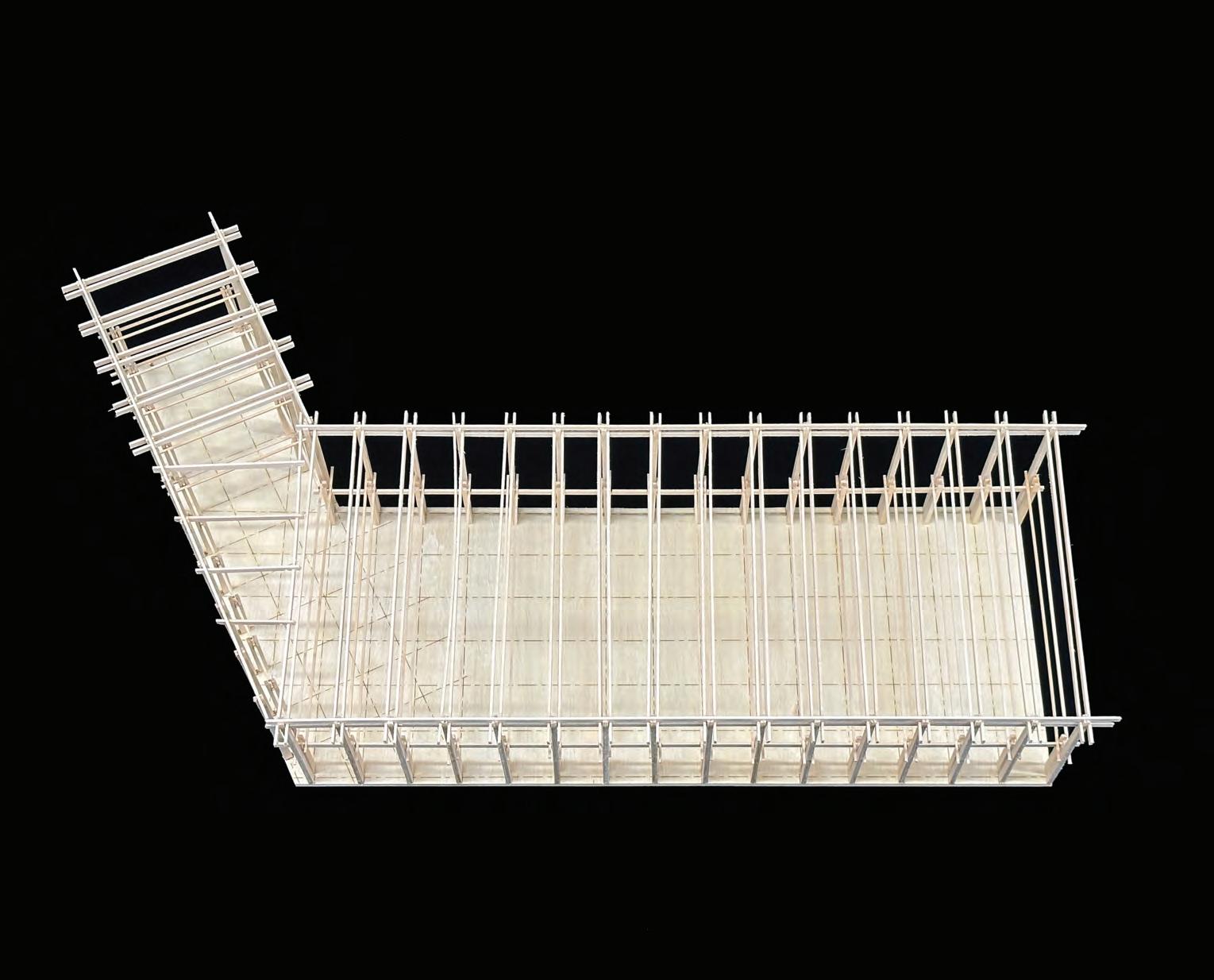
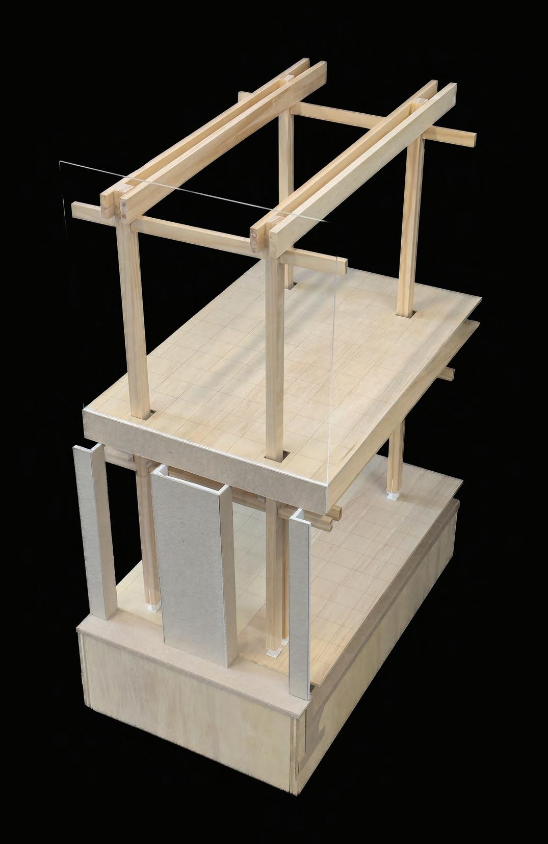
ABOUT THE STRUCTURE:
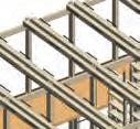
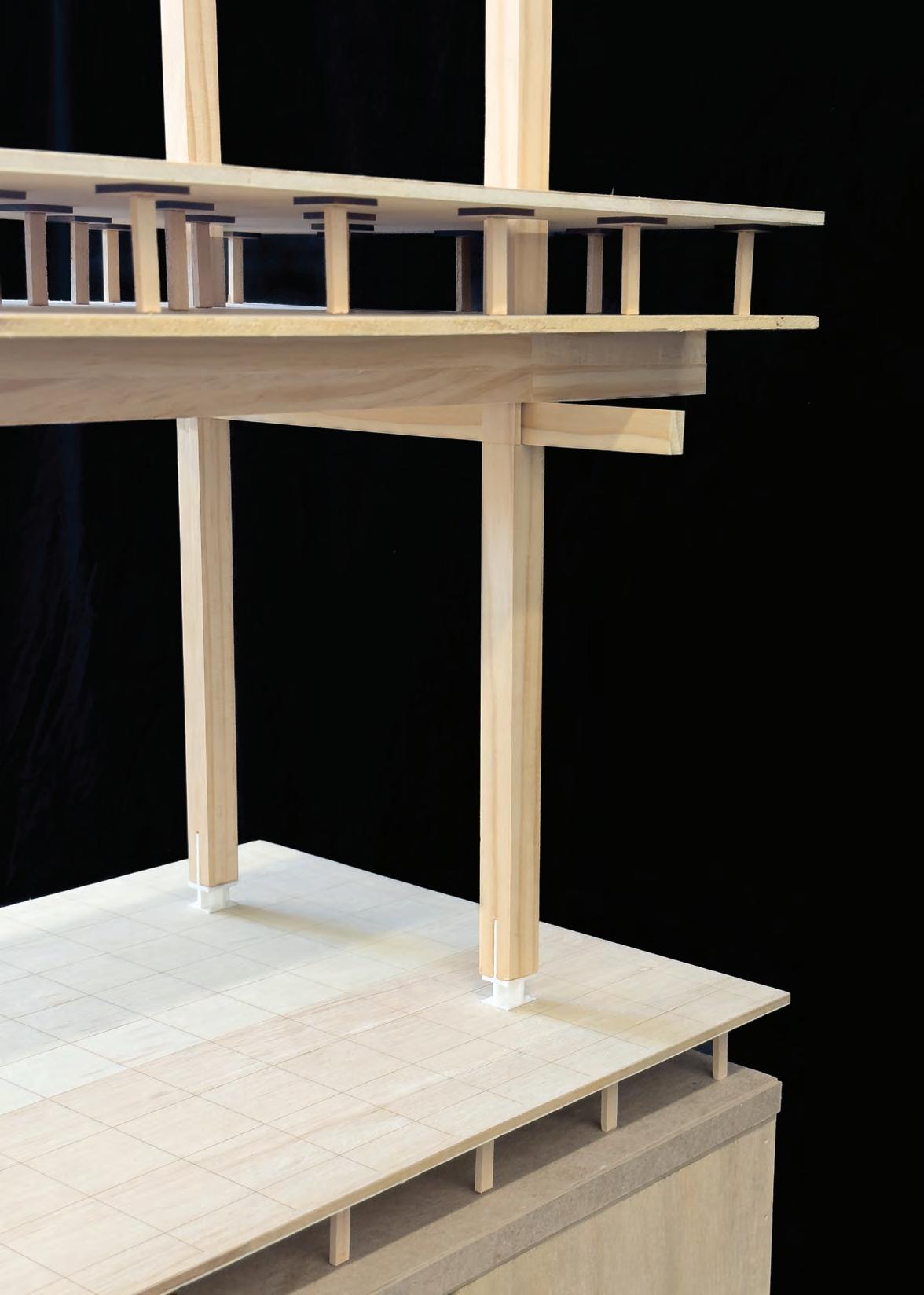
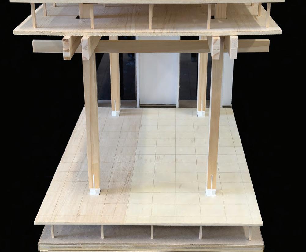
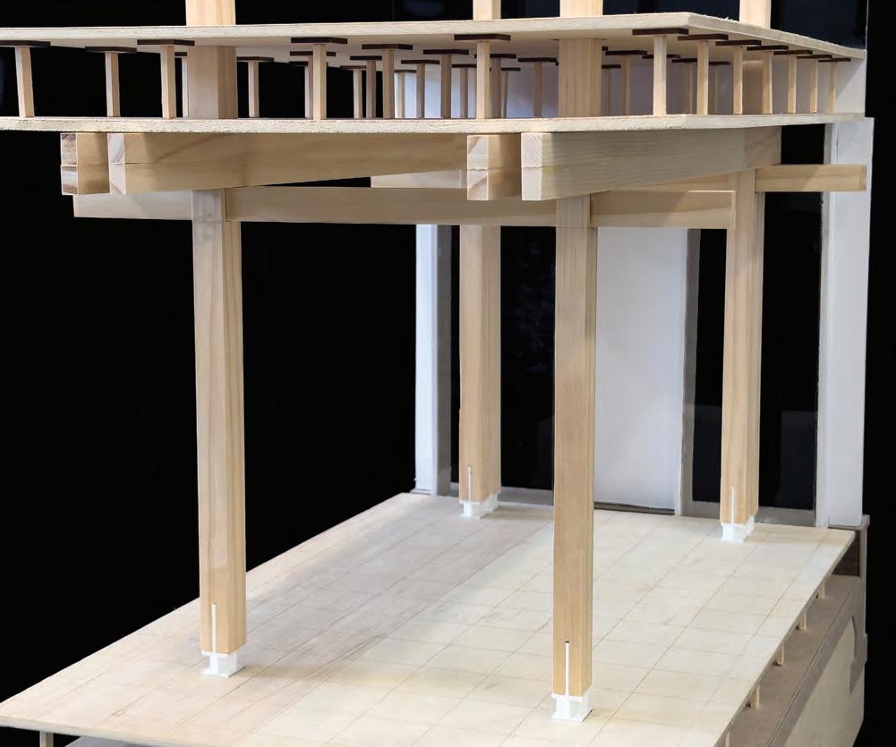
The structure of the Jane Grant Archive building is composed of heavy-mass timber that holds together through a tectonic that essentially would need no adhesive or bolts by creating a joinery where the pieces rely on each other to maintain a structure and hold weight. The pattern of the connection joint can be used on both the roof and on floor levels by repeating its process of having a column with a slit on the top to hold the girders and beams with slits at the bottom that connects to the top of the girders and lean on top of the entire joinery.
Physical Building/ Framing Model
Photographs G-10
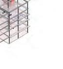
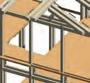
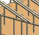
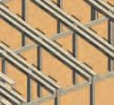
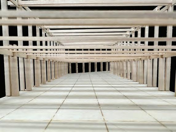
GOALS & ACCOMPLISHMENTS:
The goal of this tectonic design came from the charrette designs done previously. The goal of creating a joinery without a supporting frame or using adhesive/ bolts to keep the corner connections together. This model became a success by realizing how the construction of the joinery can lead the design. The original design looked similar except the beams were bolted to the columns in order to hold the girders. After the creation of this model, the tectonic design changed to placing the beams with slits at the bottom, on top of the girders where the joinery would fully lean on each other to stay up without adhesive/bolts.
Physical Building/ Framing Model Photographs
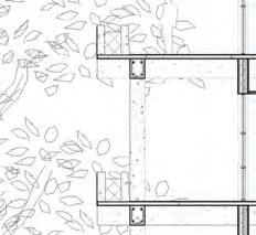
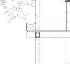
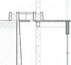
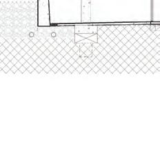
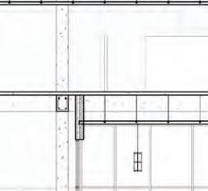
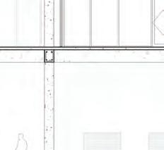
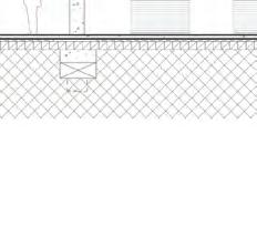
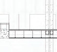
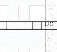
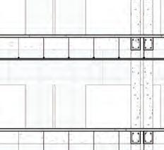
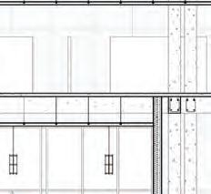
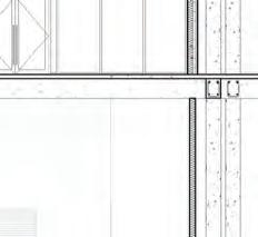
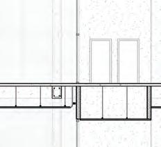
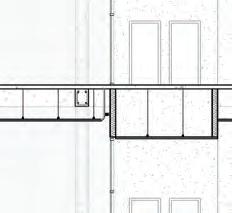
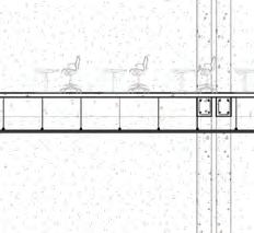
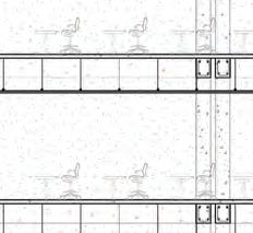
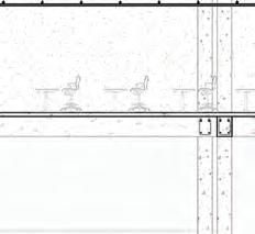
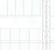
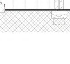
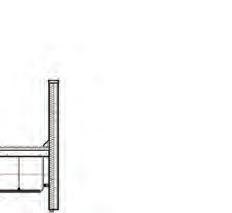
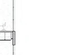
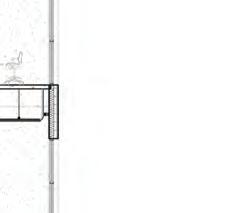
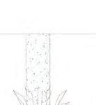
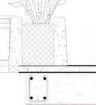
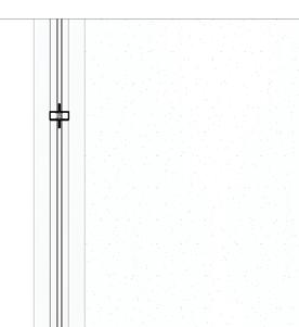
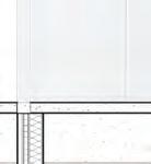
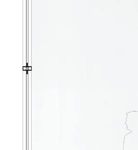
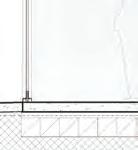
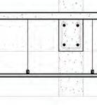
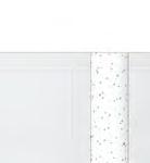
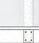
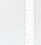
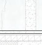
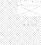
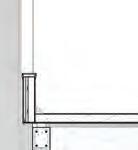
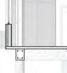
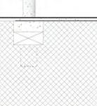
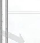
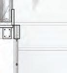
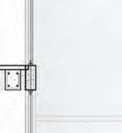
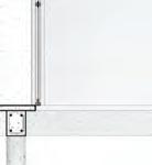
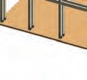
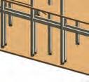
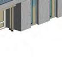
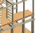
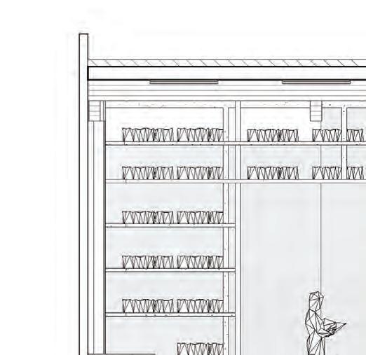
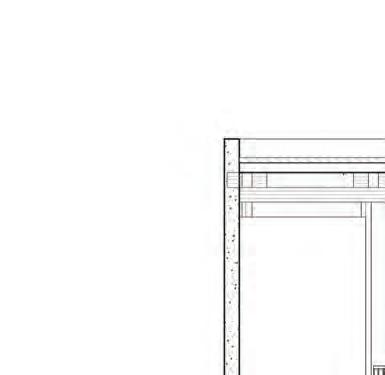
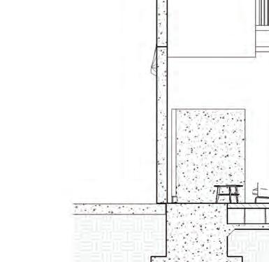
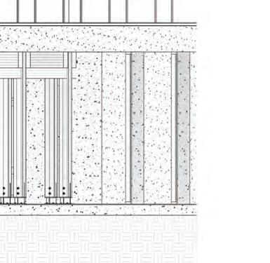
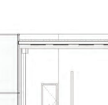
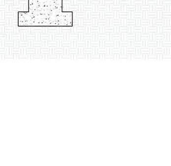
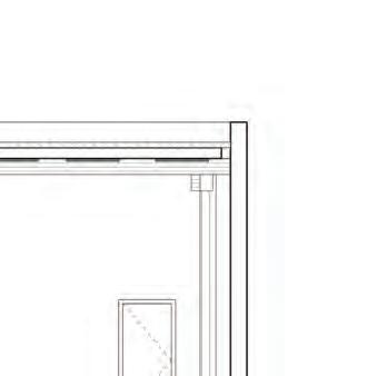
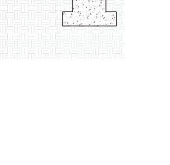
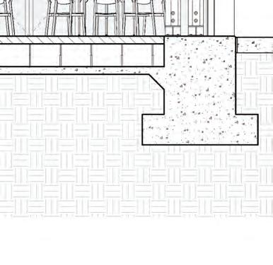
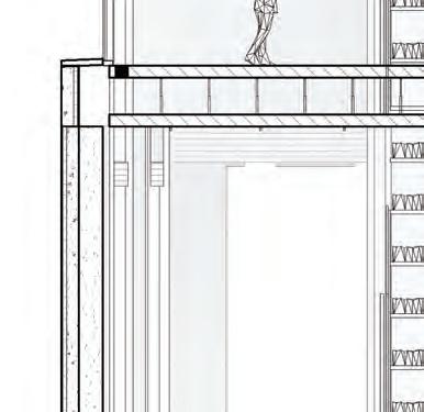
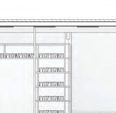
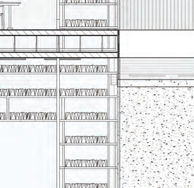
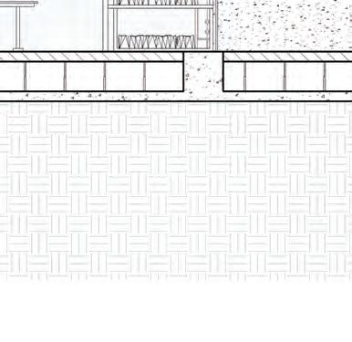
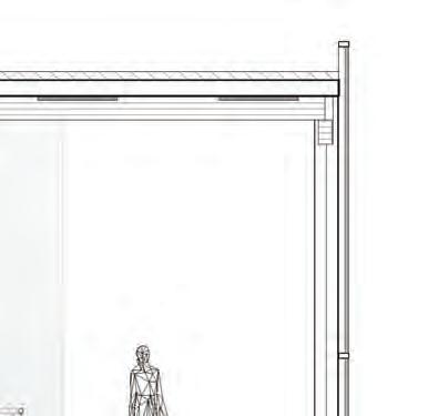
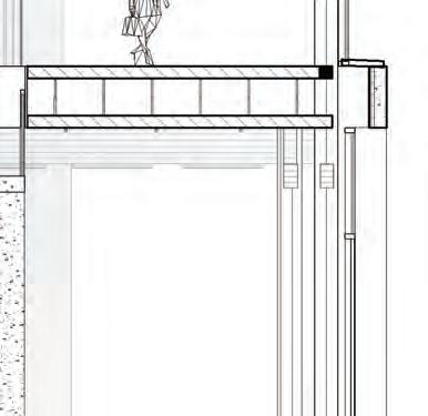
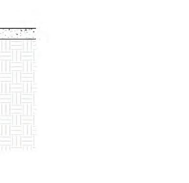
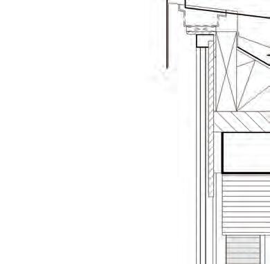
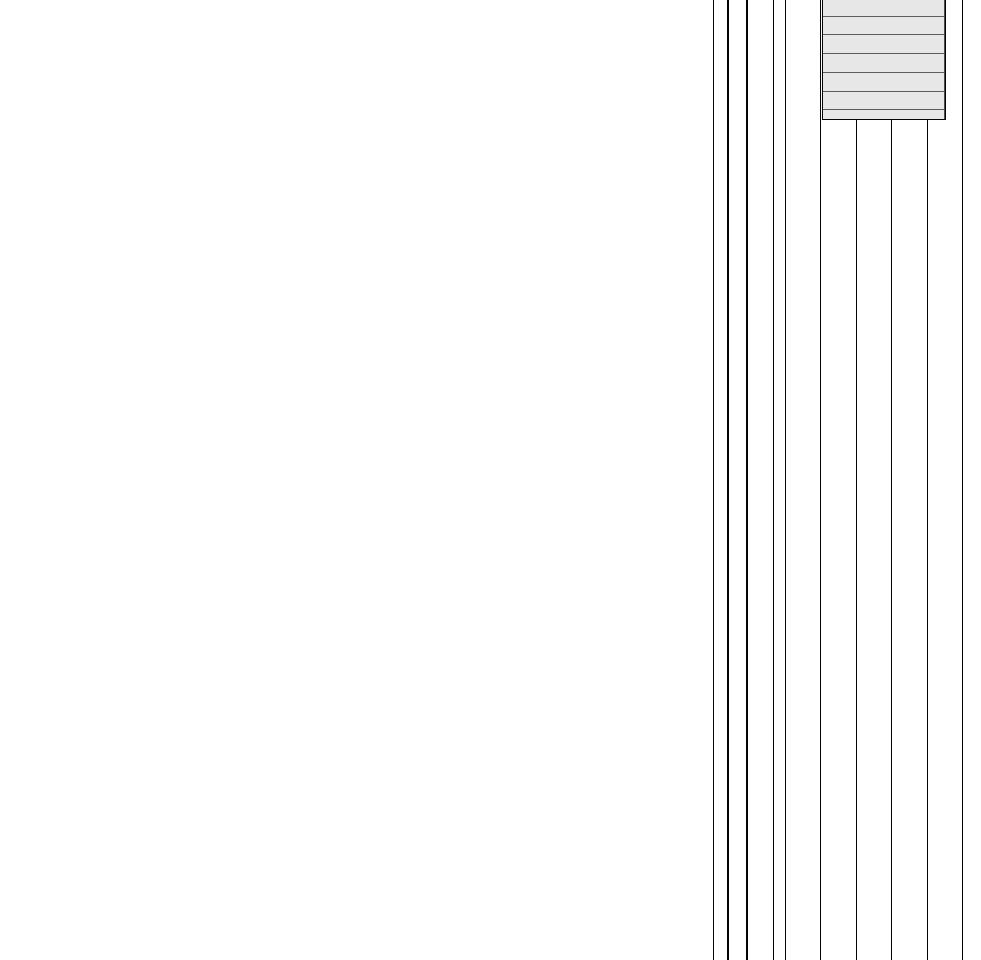
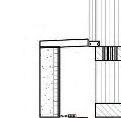
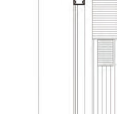
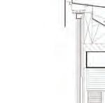
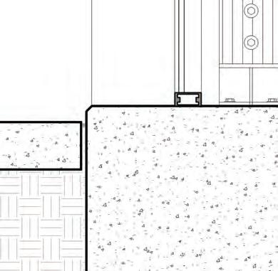
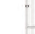
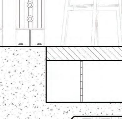
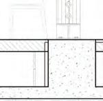
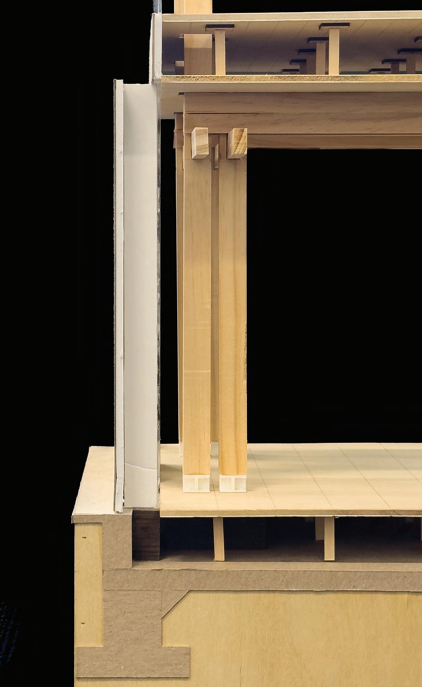
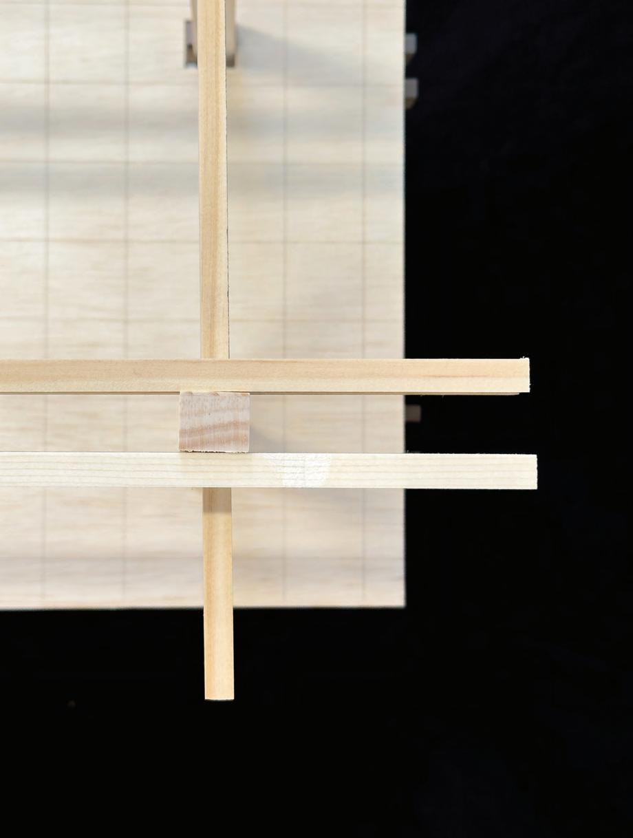
Detail Design Statement:
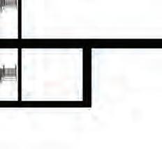
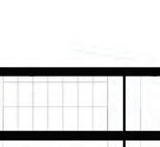
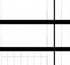
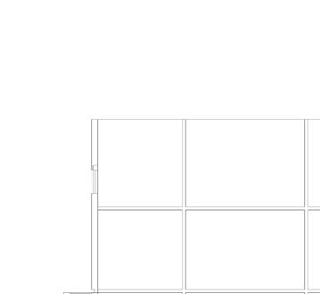
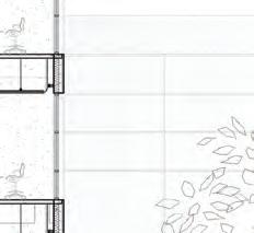
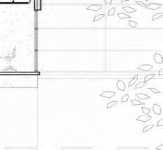
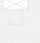
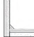
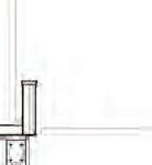
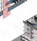
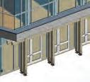
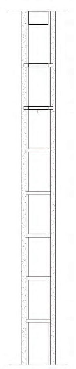
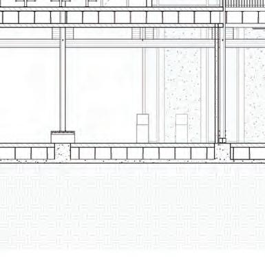
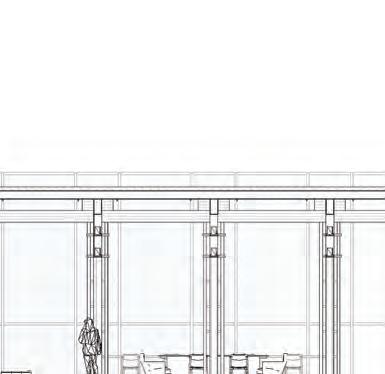
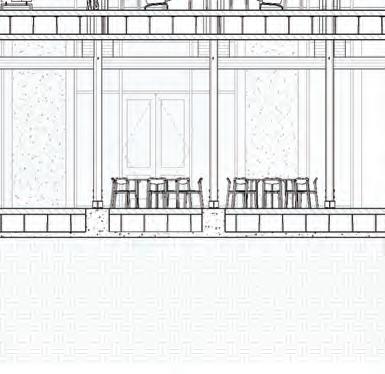
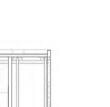
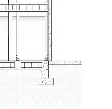
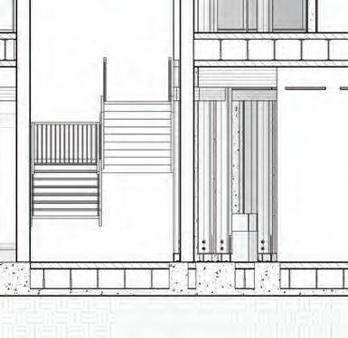
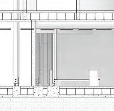
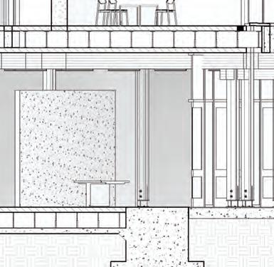
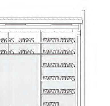
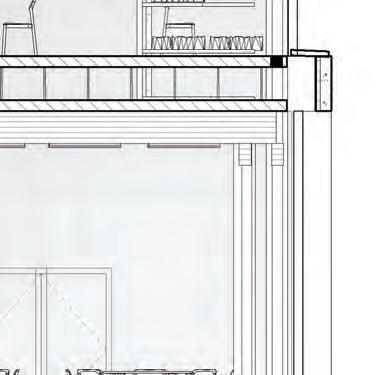
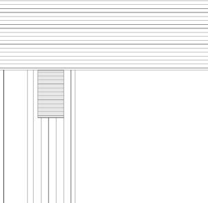
The detail design explores the use of the structural system and the use of the tectonic strategy of using pieces to rely on each other through the beams, girders, and columns. The section was taken out of the lecture room (level one) and the reading room (level two). In the reading room, you will see the bookshelves that were built in between the beams of the structural system. On the first level of the outside, you can see how there are nooks of glass that allow light inside and show you what the structural system looks like on the inside.
Detail Desgin Statement & Axonometric
Axon.
Physical Detail Model
Photographs
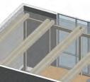
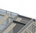
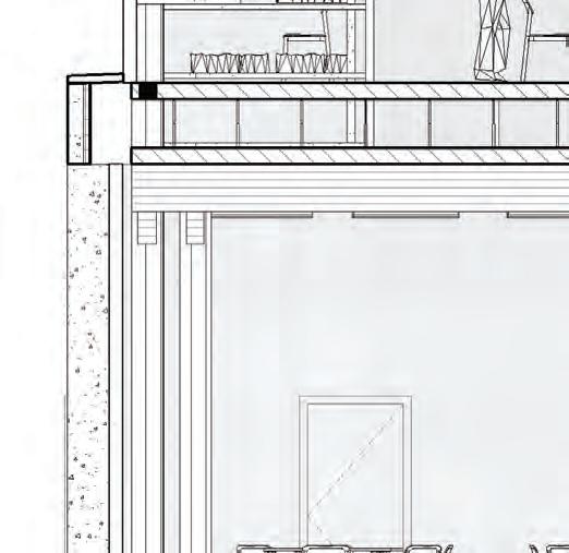
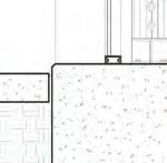
Different views from Level One to show connections of structure, column base, and raised floor system.
Physical Detail Model
Photographs H-05
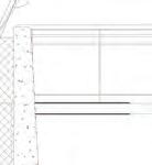
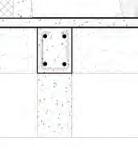
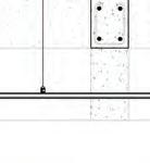
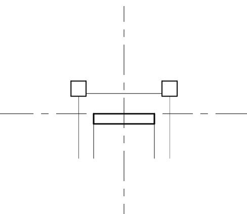
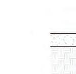
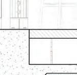
b.
Level 1 exterior wall and structure section Plan view of girder, column, and beam.