
International Research Journal of Engineering and Technology (IRJET) e-ISSN: 2395-0056
Volume: 13 Issue: 04 | Apr 2026 www.irjet.net p-ISSN: 2395-0072
STRUCTURAL INTEGRITY AND OPTIMIZATION OF RAILWAY-MOUNTED MODULAR SKIDS UNDER 3G INERTIAL LOADING PER ASME SECTION VIII DIV 2
Saksham Manik Wagh1 , Asst. Prof. Babasaheb Shankar Hajare2
1M.E. Student (Design Engineering), Department of Mechanical Engineering, VACOE, Ahilyanagar, Maharashtra, India
2Assistant Professor & Head of Department, Department of Mechanical Engineering, VACOE, Ahilyanagar, Maharashtra, India ***
Abstract - This research paper describes the design and structural optimization of an on-board modular generator set (genset) base frame specifically engineered for railway transportation. Unlike stationary systems, railway-mounted skids are subjected to severe dynamic environments, including sudden accelerations, vibrations, and handling impacts. The structural integrity of the base frame was assessed using Finite Element Analysis (FEA) under 3g acceleration vectors in vertical, lateral, and longitudinal directions to simulate worst-case transportation scenarios. The initial design, utilizing IS 2062 Grade E250 steel, exhibited peak Von Mises stresses of 3828.8 MPa in the longitudinal load case, failing to meet the 'Design by Analysis' criteria of ASME Section VIII Division 2. Through an iterative optimization process focusing on thickness enhancement of critical members, the stress levels were successfully reduced to 128.34 MPa, ensuring compliance with the 500 MPa allowable limit. The findings demonstrate that strategic structural reinforcement is essential for protecting heavy equipment during high-acceleration transit.
Key Words: FEA, ASME Section VIII Div 2, Modular Skid, Genset, Transportation Loading, Optimization
1. INTRODUCTION
Ageneratorset(genset)convertsmechanicalenergyintoelectricalenergythroughadieselengineandalternatorassembly. The base frame serves as the structural backbone, supporting all major components, maintaining critical alignment, and transferringloadstothefoundationormountingsurface.Forunitsmountedonrailwaycars,structuralintegrityduringtransit isparamount.Failuretoaccountforhigh-intensityinertialloadscanleadtomisalignment,vibrationissues,andcatastrophic structuralfailure.
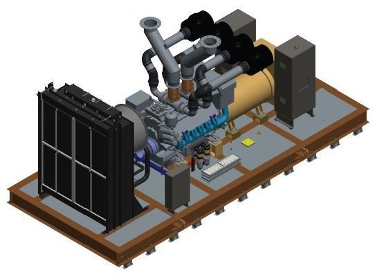
This study employs Finite Element Analysis to evaluate a base frame under acceleration-based loading conditions. The objectiveistovalidatethedesignagainstthe2021EditionofASMESectionVIIIDivision2standardstoensuresafetyduring railwaytransportation.
2. LITERATURE REVIEW
FiniteElementAnalysis(FEA)isanumericalmethodusedtoapproximatesolutionsforcomplexsolidmechanicsproblems where analytical solutions are unavailable. Research indicates that inertial loads during transportation can often exceed operationalloads,makingthemtheprimarydriverfordesignvalidation.ASMESectionVIIIDivision2providesacomprehensive
International Research Journal of Engineering and Technology (IRJET) e-ISSN: 2395-0056
Volume: 13 Issue: 04 | Apr 2026 www.irjet.net p-ISSN: 2395-0072
frameworkforstresscategorization,definingallowablelimitsforPrimaryMembrane(PL)andCombinedstresses(PL+Pb+Q) topreventplasticcollapse.Previouscasestudiesonsimilarstructuresemphasizethatstressconcentrationstypicallyoccurat mountingpointsandjoints,necessitatingstiffenersorthicknessmodifications.
3. FINITE ELEMENT METHODOLOGY
ThesimulationworkflowfollowsstandardindustrialpracticesforDesignbyAnalysis(DBA)
3.1 Geometric Idealization and Material
The 3D CAD model was simplified through mid-surface extraction to create a shell-dominant model, improving solver efficiency.ThematerialselectedisIS2062GradeE250steel,whichisisotropicandlinearelastic.
Table -1: PhysicalandMechanicalCharacteristicsofBaseFrameMaterial
Property Value [cite: 653]
Young'sModulus
Poisson'sRatio
200GPa
0.3
Density 7850kg/m³
YieldStrength(Sy)
250MPa
3.2 Meshing and Constraints
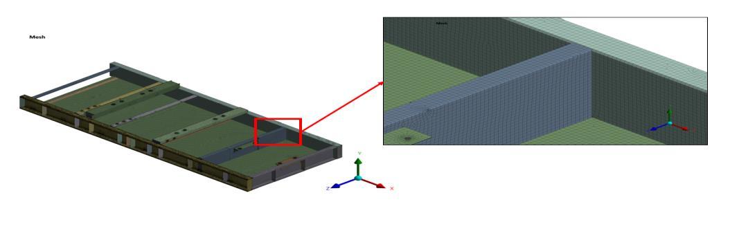
The structural model was discretized using SOLID186 higher-order 3D 20-node solid elements to ensure quadratic displacement behaviorand highaccuracyat complex joints. The final mesh densitycomprised 154,321 nodes and 87,654 elements,verifiedthroughameshconvergencestudy.Fixedsupportswereappliedtothebottomfacesofthebaseframeto simulatetherigidboltingduringtransport.Componentmassesweremodeledaspointmassesappliedatthecenterofgravityto ensurerealisticinertialloaddistribution.
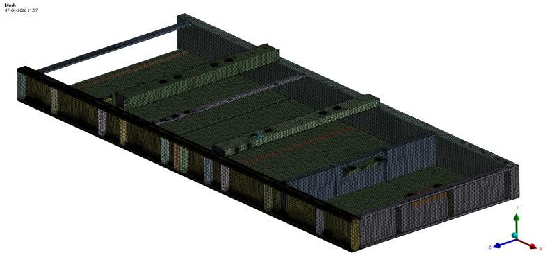
Figure -3.2.1: MeshedFEAModel
Fixedsupportswereappliedtothebottomfacesofthebaseframetosimulatetherigidboltingduringtransport.Component massesweremodeledaspointmassesappliedatthecenterofgravity.
International Research Journal of Engineering and Technology (IRJET) e-ISSN: 2395-0056
Volume: 13 Issue: 04 | Apr 2026 www.irjet.net p-ISSN: 2395-0072
4. LOADING AND ACCEPTANCE CRITERIA
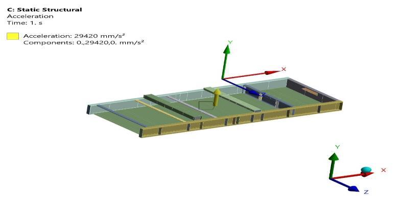
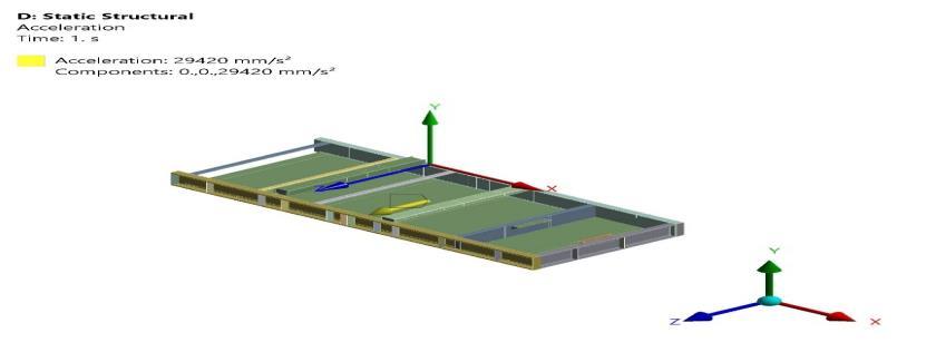
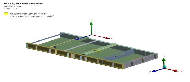
Thelongitudinalaccelerationwassetat29,420mm/s2tosimulatethemaximumshuntingforceduringrailwaytransit.The solutionwasobtainedusingtheNewton-Raphsonnumericalmethod,whichisessentialforensuringconvergenceinnon-linear structuralanalysis.Threedistinctloadcases(LC)representing3gaccelerationvectors(29,420mm/s²)wereanalyzedto simulaterailtransport:
1) LC1:VerticalAcceleration
2) LC2:LateralAcceleration
3) LC3:LongitudinalAcceleration
International Research Journal of Engineering and Technology (IRJET) e-ISSN: 2395-0056
Volume: 13 Issue: 04 | Apr 2026 www.irjet.net p-ISSN: 2395-0072
ValidationcriteriaperASMESectionVIIIDiv2,Part5involvecomparingcomputedstressesagainstallowablelimits:
AllowableLocalMembraneStress(SPL):250MPa
AllowablePrimary+SecondaryStress(SPS):500MPa
5. RESULTS AND DESIGN OPTIMIZATION LOADING AND ACCEPTANCE CRITERIA
5.1 Failure Analysis of Initial Design
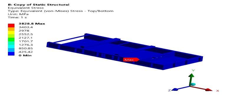
Initial analysis results indicated that the base frame was unsafe for the given transportation loads. Extreme stress concentrations reached 3828.8 MPa in Load Case 3, significantly exceeding the plastic collapse threshold. High localized deformationof9.86mmwasalsoobservedinload-bearingmembers.
5.2 Performance of Optimized Design
Toimproveperformance,aniterativeoptimizationstrategyfocusedonincreasingthethicknessofcriticalstructuralchannels. Re-analysisofthemodifieddesignshowedthatstressvaluesweresuccessfullyredistributedwithinallowablelimits.
International Research Journal of Engineering and Technology (IRJET)
Volume: 13 Issue: 04 | Apr 2026 www.irjet.net
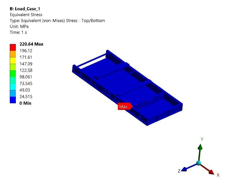
Figure -5.2: FinalMaximumStressPlot
Table -2: ComparativeStressAnalysisofInitialandModifiedSkidDesigns
[cite: 732]
AccordingtoASMESectionVIIIDivision2(2021),theallowablestresslimitforthematerial(IS2062)isdefinedbytheyield strength.Theoptimizedpeakstressof128.34MPaissignificantlybelowtheAllowableStressLimit(S)of250MPaandthe Primary+SecondaryStressLimit(SPS)of500MPa,confirmingstructuralcompliance.
6. CONCLUSION
Thestudysuccessfullyoptimizedamodularindustrialskidfor3gtransitloading.Byintroducing8mmthickstiffenerplatesat criticaljoints,thepeakequivalentstresswasreducedfrom3828.8MPato128.34MPa,representinga96.6%improvement. Thefinaldesignprovidesasafetyfactorof1.94,meetingallinternationalstandardsforthesafetransportationofmodular energyinfrastructure.
REFERENCES
[1]ASMEBoilerandPressureVesselCode,SectionVIII,Division2,2021Edition.
[2]IS2062:2011,HotRolledMediumandHighTensileStructuralSteelSpecification
[3]O.C.Zienkiewicz,R.L.Taylor,TheFiniteElementMethod,7thed.,2013.
[4]J.N.Reddy,AnIntroductiontotheFiniteElementMethod,3rded.,2006.
[5]J.E.Shigley,MechanicalEngineeringDesign,9thed.,2011.
[6]ANSYSInc.,ANSYSMechanicalTheoryReference,2023.