

International Research Journal of Engineering and Technology (IRJET) e-ISSN: 2395-0056
Volume: 13 Issue: 04 | Apr 2026 www.irjet.net p-ISSN: 2395-0072
STRUCTURAL ANALYSIS AND OPTIMIZATION OF AN ELECTRIC VEHICLE CHASSIS
P Manikandan1 , S Dhamodharan2 , NV Dhandapani3 , G sureshkannan 4
1 Post Graduate Student ,Department of Mechanical Engineering, KIT-Kalaignarkarunanidhi Institute of Technology, Coimbatore, India
2 Professor , Department of Mechanical Engineering, KIT-Kalaignarkarunanidhi Institute of Technology, Coimbatore, India
3 Professor , Department of Mechanical Engineering , Karpagam College of Engineering, Coimbatore, India
4 Professor , Department of Mechanical Engineering , Coimbatore Institute of Technology, Coimbatore, India
Abstract - The vehicle chassis is the major structural framework for a vehicle system. Its principal function is to safely carry the maximum load for all designed operating conditions. This study focuses on the structural analysis and optimization of an electric vehicle chassis, with the objective to minimize stress and maximize the fatigue life. The methodology combines CAD, theoretical calculations, and Finite Element Analysis using ANSYS. The chassis, based on a C-channel section, was analysed for a gross vehicle weight of 770 kg. Theoretical validation found the design to be safe, with a calculated stress below the permissible stress and a maximum deflection less than the allowable deflection. FEA confirmed that maximum deformation occurs at the middle of the chassis. Based on the generated bending and torsion load cases and fatigue life analysis, the proposed chassis design using aluminium is considered safe. Future work includes modal analysis and vibration analysis and improving strength by adding gussets.
Key Words: Electric Vehicle Chassis, Finite Element Method, Structural Steel, Aluminium 6061, Stress Analysis, Fatigue Life and Optimization.
INTRODUCTION
The global automotive industry is currently undergoing a transformative period, driven by the increasingneedforsustainability,improvedfueleconomy, and reduced emissions. This shift has positioned electric vehicles (EVs) as an attractive alternative to conventional combustion engine cars. Successfully navigating this transitionrequiresinnovativedesignstrategiesfocusedon maximizingenergyefficiency,extendingdrivingrange,and optimizingoverallvehicleperformance.
The vehicle chassis is a major component in a vehicle system, serving as the framework for mounting components such as the engine, transmission system, axles, wheels, and electrical systems. The chassis of an electric vehicle is its framework, integrating main componentslikethewheelmotor,battery,andtires.
The principal function of the chassis is to safely carry the maximum load for all designed operating conditions. Key characteristics determined through static and dynamic analysis include identifying the location of the critical stress area and determining the maximum deformation, strength, and stiffness of the chassis. The chassis must be rigid enough to withstand shock, twist, vibration, and other stresses, accommodating twisting on uneven road surfaces and absorbing vibration from the battery and wheel motor. The chassis is typically loaded by static, dynamic, and cyclicloading.
1.1. Chassis Failures and Mitigation
Fatigue is estimated to be responsible for 85% to 90% of all structural failures or crack propagation on the chassis. The vehicle powertrain is also significantly impacted by vibration and noise. To overcome these failures,theconceptofaSub-framehasbeenintroduced.
1.2. Types of Electric Vehicle Chassis
The overall design of a car body consists of two parts: the chassis and the bodywork (or superstructure). Some EV chassis designs are equipped with an open-box bed and a hydraulic lift. The Volkswagen Group has licensed its MEB electric chassis to the German start-up e.Go , a platform that can be used for a variety of car models.
The US start-up Bollinger Motors bases its B1 (offroadvehicle)andB2(pickup)modelsonthesameelectric chassis platform, similar to the skateboard platform used bycompanieslikeRivian.
2 Literature Review
A review of prior work related to vehicle structural design, analysis, and optimization found that chassis analysisprimarilyinvolvesstressanalysistopredictweak pointsandfatigueanalysistopredictthelifeofthechassis.
International Research Journal of Engineering and Technology (IRJET) e-ISSN: 2395-0056
Volume: 13 Issue: 04 | Apr 2026 www.irjet.net p-ISSN: 2395-0072
2.1 Static and Dynamic Analysis Researchers used CAE Software for modelling and simulation, considering self-weight for static analysis and Acceleration, Braking, and Road Roughness for dynamic analysis. Stresses caused by braking were observed to be greater than those from acceleration. Dynamic analysis involves determining characteristics such as natural frequency,frequencyresponse,andmodeshapeusing the Finite Element Method. In one heavy vehicle study, the dominant loading was understood to come from the cargo as static loading, with road roughness having nosignificanteffectonthestress.
2.2 Finite Element Method (FEM) and Optimization
Failure Simulation and Improvement: Hyper mesh and Opti-struct software were used to analyse and simulate the failure of a light commercial vehicle chassis. Introducing local stiffeners reduced the magnitude of stress in the modified chassis by 44%. To overcome failure in a longitudinal stringer, six different types of reinforcementwereinvestigatedusingHypermesh,with the sixth type yielding the best results. This software analysis helped eliminate many laboratory tests, reducingtestingcosts.
Material and Weight Optimization: Studies analyzed alternative materials (e.g., AL and steel) and variouscrosssectionslikeC,I,andBoxtype.Optimizing the thickness of a middle tonnage truck chassis using FEMsuggestedthata4mmthicknesswassafetocarrya 15-ton load. Numerical results on a truck chassis with riveted joints showed that stresses on the side member could be reduced by increasing the side member thickness.
2.3 Problem Statement and Objectives
GrossVehicleWeightandbatterypowerarethe two most important parameters influencing a vehicle's performance. An increase in vehicle weight can lead to moreaccelerationandincreasedvibration onthechassis.Theindustryrequiresgoodride comfort, necessitating a chassis with a high-strength crosssectiontominimizefailuresandalowweight.
A material with a low density and higher compressive and bending stress would help reduce weightwhilemaintainingsafetransmission.Thecurrent probleminelectricvehicles isthattheloadactingonthe sub-frame due to the powertrain provides continuous vibration, which decreases the fatigue life of the main frame.
Objective: Theeffortofthepresentworkisto optimizethesub-frameand,therefore,thechassis.The goalistominimizethestressandmaximizethefatigue lifeofthechassis.
3 Methodology & Flow chart
Theanalysisofthechassisusesamethodologythat combines
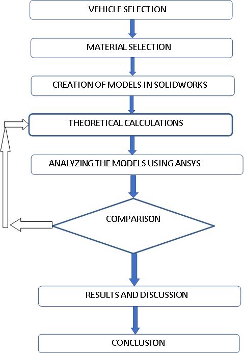
1. Methodology & Flow chart
Computer-Aided Design, theoretical calculations, and Finite Element Analysis (FEA), as illustrated in the flow chart
3.1
Material Selection
Thematerialchosenforthechassisisstructuralsteelwith the constraint of having a low density and high strength. ThevehicleframeisconstructedfromstandardC-channel andhorizontal beamtypemembers.Thepropertiesofthe testedmaterialsareshowninTable1.
International Research Journal of Engineering and Technology (IRJET) e-ISSN: 2395-0056
Volume: 13 Issue: 04 | Apr 2026 www.irjet.net p-ISSN: 2395-0072
Table1.MaterialProperties
MaterialProperties Highstrengthstructuredsteel
Young‘sModulus(E) 2.10e+005MPa
Poissonratio(μ) 0.3
YieldStrength Range230Mpato410MPa
UltimateStrength 360MPa
Density 7.85e-006kgmm^-3
MaterialProperties Aluminium6061
Young‘sModulus(E) 70,300MPa
Poissonratio(μ) 0.3
YieldStrength Range125Mpato290MPa
UltimateStrength 275MPa
Density 2.66e-006kgmm^-3
3.2 Vehicle Specifications
The total load acting on the chassis is the Gross Vehicle Weight,whichisthesumoftheNetVehicleWeightandthe Payload.
Table2.VehicleOverAllDimension
Parameter
ValueSource
Lengthofthevehicle 2100mm
NetVehicleWeight 600kg
Payload 170kg
GrossVehicleWeight (GVW) 770kg
Theoretical Design Validation
Over All Design CalculationFigure 2. Loading Condition.asimplysupportedbeamwithsupportsat points A and B, each located 300 mm from the respective ends C and D, subjected to a central downward point load of 7554 N applied at the midpoint between A and B, spanning a distance of 1498mm
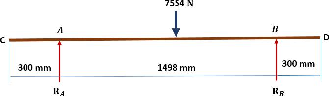
Figure2 LoadingCondition
The chassis was modeled as a simply supported beam with a central point load of 7554 N. The reaction forces were calculated as ���� + ����=7554��
���� ∗1498 =7554∗1498/2 ���� =5657946/1498
���� =����������
���� =7554 3777
���� =����������
Maximumallowabledeflectioninbeam = 0������������������������/GROUNDCLERANCE
= 2098/350 = 6MM
The E-vehicle chassis has two longitudinal members with cross sectional members. Generally, C –channelsareusedinthevehiclestructuresavailableinthis particulartypeofvariantinthemarket.TheCchannelhas beenselectedonthebasisofbendingstressinducedinthe structure. Deflection produced in the structure for structuralsteelandAluminium.
Where,h=100mmandb=50mmT=6 ������ =150828000����4
���� = 42500����3 �������� = 69360000������
Permissiblestress= YIELDSTRENGTH /FACTOROFSAFTEY
=360/2=180 N/
Accordingtothebendingequation = =
Stressproducedinthebeam = / =69360000/42500
163.2 ⁄����2
Since is less than the permissible stress. Hence, the designissafe
AccordingtoMacaulay’sTheoremthemaximumdeflection isproducedinbeamis ������ =�� X withrespecttoxweget ������ =EIX
Again withrespecttoxweget
International Research Journal of Engineering and Technology (IRJET) e-ISSN: 2395-0056
Volume: 13 Issue: 04 | Apr 2026 www.irjet.net p-ISSN: 2395-0072
Therefore,maximumdeflectionisproducedinbeam
ymax=
ymax = 13.29mm(Tensileandcompression)
Maximum Deflection (y max), based on Macaulay’s
Theorem: y max≈13.29mm.
MaximumAllowableDeflection:17.4mm.
Conclusion: Since the calculated maximum deflection (13.29mm)islessthanthemaximumallowabledeflection (17.4 mm), the design is also considered safe from a deflectionstandpoint.
Results of Finite Element Analysis
The CAD model was imported into the ANSYS preprocessing environment as anIGS fileand meshed in 3D usingtetraelements.
Figure 3 Ansys Geometric Model shows a 3D model of a closedframestructuremadeofseveralconnectedstraight segments, each shown in different colors to represent separate partsofthegeometry.
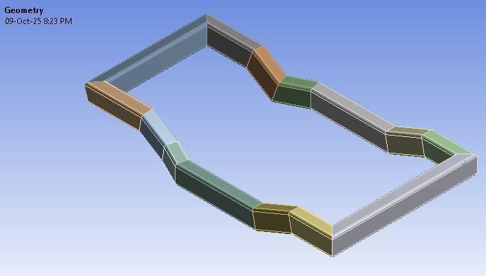
Figure3MeshModel.themeshedgeometryusedfor structuralanalysisoftheframe.
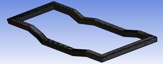
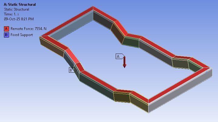
Figure 4 shows the loading and boundary conditions applied for the Static Structuralanalysisoftheframe.
Figure 4loadingandboundaryconditions
Bendingandtorsionwereevaluatedasthemaximumload cases, with the vertical load case found to be the most severe.
Total Deformation The maximum total deformation wasfoundtobeatthe
Figure 5 show the Total Deformation results from the static structural analysis of the frame under different loadingconditions.
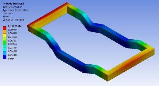
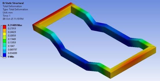
5 TotalDeformationvalueforStructuralSteeland Aluminium middleofthechassis.Thedeformationgradually decreasedfromthemiddletowardsthefrontandback.
Material MaximumTotal Deformation Source
StructuralSteel
mm Aluminium(Al) 0.314mm
Von-Mises Stress Distribution The maximum VonMises stress was obtained for both bending and torsioncases:
International Research
Volume: 13 Issue: 04 | Apr 2026 www.irjet.net p-ISSN: 2395-0072
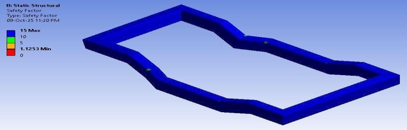
Figure 6 show the Equivalent (von-Mises) Stress distributionacrosstheframeundertheanalyzedloads.
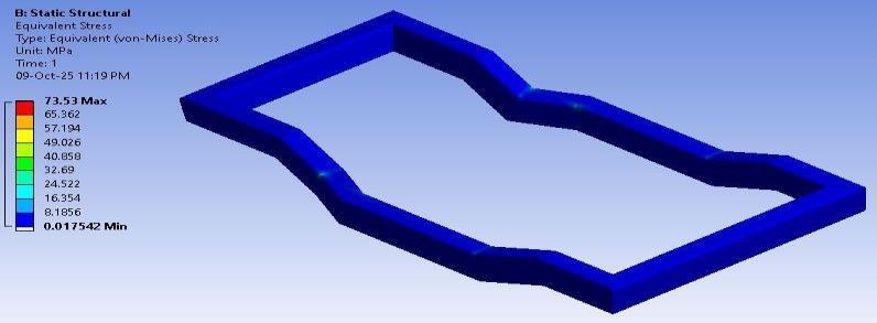
Figure 6 Von-MisesStressvalueforStructuralSteeland Aluminium
MaximumVon-MisesstressforSteel:73.63MPa.
MaximumVon-MisesstressforAluminium:75.53MPa.
ShearStress(BendingandTorsion)
Torsion, which is the twisting of an object due to an appliedtorque,wasalsoreferredtoas theleftrampload andrightramploadconditions.
Figure7showthedistributionoftheMaximumPrincipal Stressacrosstheframeforbothanalysiscases.
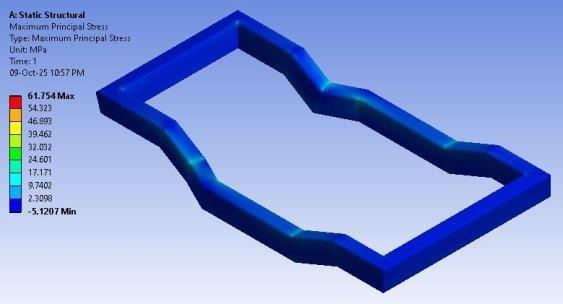
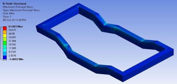
Figure 7 MaximumPrincipleStressvalueforStructural SteelandAluminium
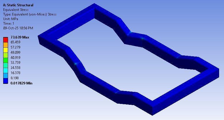
Figure 8 Show the Factor of Safety (F.S.) distribution for the frame, demonstrating the component'ssafetymargin
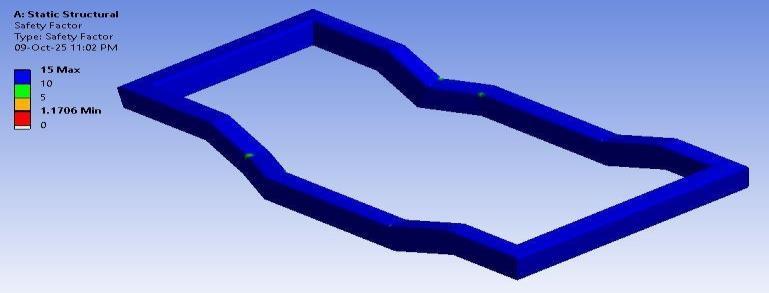
Figure 8 Safety Factor value for Structural Steel and Aluminium
Conclusion
The electric vehicle chassis was successfully analyzedusingCAEsimulationsoftware(ANSYS).
The results show that the maximum deformation and maximum stress distribution are within the standardandrecommendedvalues.
The maximum deformation is located at the middleofthestructure.
Theanalysisofthegeneratedbendingandtorsion load cases and fatigue life indicates that the proposed chassis design with aluminium will be safe.
For future improvements, the stress concentration areas of the chassis structure can be addressed to improve strength and increase stiffness by adding gussets. Future scope of work includesperformingmodal analysisandvibration analysisofthechassis.
International Research Journal of Engineering and Technology (IRJET) e-ISSN: 2395-0056
Volume: 13 Issue: 04 | Apr 2026 www.irjet.net p-ISSN: 2395-0072
References
[1] Alireza ArabSolghar, ZeinabArsalanloo(2013). Were studied about the chassis of Hyundai CruzMinibus.
[2] CicekKarao, glu, N. SefaKuralay (2001). Have analyzed truck chassis with riveted joints usingFEM.
[3] K. Chinnaraj, M. Sathya Prasad, Lakshmana Rao (2008). Have chosen to optimize the weight of chassisframeassemblyofaheavytruck.
[4] Kurdi, O., & Rahman, R. A. (2010). Studied the road roughness effects on stress distributionofheavyvehiclechassis.
[5] KutayYilmazcoban, Yasar Kahraman (2011). Have studied and optimized thethicknessof a middle tonnage truck chassis by using Finite Elementtechnique.
[6] M. Ravichandra, S. Srinivasalu, Syed altaf Hussain (2012). Have discuss about the alternatematerialforchassis.
[7] N.K.Ingole, D.V. Bhope (2011). Analyzed the Tractor Trailer made by Awachat Industries, Wardhatoreducethemanufacturingcost.
[8] Roslan Abd Rahman, Mohd Nasir Tamin, Ojo Kurdi (2008). Has used FEM software and determine stress analysis as a preliminary data forfatiguelifeprediction.
[9] S.S Sane, Ghanashyam Jadhav, H. Ananadaraj (2008). Analyzed the light Commercial Vehicle chassis using FEM and simulatedthefailureduringtesting.
[10]Teo Han Fui, Roslan Abd. Rahman (2007). Have explained about the 4.5 Ton truck chassis againstroadroughnessandexcitations.
[11]Veloso, V., Magalhaes, H. S., Bicalho, G. I., & Palma, E. S. (2009). Studied the Failure of longitudinalstringerofvehicle.
[12]Vijaykumar V. Patel, R. I. Patel (2012). Have studied the Ladder chassis frame ofEicherE2 bystaticstructuralanalysis.
[13]Yongjie Lu, Shaopu Yang, Shaohua Li, Liqun Chen(2009).Have developedvirtual prototype modelofheavydutyvehicle(DFL1250A9)using multibodydynamics.
[14]Zhongzhe D, Ping Z. (2006). Has performed Fatigue life analysis and improvement of the autobodyinasportsutilityvehicle(SUV)