
International Research Journal of Engineering and Technology (IRJET) e-ISSN: 2395-0056
Volume: 13 Issue: 03 | Mar 2026 www.irjet.net p-ISSN: 2395-0072
International Research Journal of Engineering and Technology (IRJET) e-ISSN: 2395-0056
Volume: 13 Issue: 03 | Mar 2026 www.irjet.net p-ISSN: 2395-0072
Ashutosh Yadav, Tanmay Agarwal, Vishal Chaskar Tata Technologies, Pune, India
Abstract - As the automotive industry expects rapid transition towards electrification, the packaging of most complex and safety critical component also seen as a mammoth task. Our study presents a systematic packaging strategy and location-finalization methodology for integrating a lithium-ion battery pack into a small passenger vehicle. Batteries occupy significant space in electric commercial vehicles, making battery placement a critical design decision. Deciding on battery pack location has impact on various factors like vehicle CG, Vehicle Load distribution, packaging of surrounding aggregates, safety of the battery pack and also of the occupant, Cost impact etc. to name a few. In the electric conversion of the passenger small commercial vehicle, various locations were evaluated underfloor, rooftop, under-seat, rear overhang & under cabin with respect to C.G, lateral load transfer, tractive effort, energy consumption & available traction on wheels.
Each option posed unique challenges like elevated center of gravity, increased drag & traction limited torque. In this study, detailed packaging studies, certain vehicle calculation are made and each location are evaluated with its pros and cons. Study also proposes preferred location for such vehicles. This study provides practical insights into safe, efficient, and scalable battery packaging for small passenger EV platforms.
Key Words: Small Passenger Vehicle, Battery Packaging, Vehicle C.G, Load Distribution,M2 Category.
Globaldemandforcarbonnetzeroaimstobalancegreenhousegas(GHG)emissionswithremoval,targetingnet-zeroby2050 (orlaterforsomedevelopingcountriesby,2070)tolimitglobalwarmingto1.5°C.Thisdemandhasemphasizedonrapid electrificationoftransportationsystemacrossthenationslikeIndiaandChina.WhileelectrificationofLocomotiveshasgained andachievedgoodstabilitybuttheautomobileindustryisstilllackingthatgrowthconsideringkeyparameterslikeVehicle Range,Safetyofkeycriticalcomponentlikebatterypacks,andpackagingoflargerbatterypacksintothevehicle.
Therapidelectrificationofthepassengervehiclesegment particularly-carryingpassengercommercialtransportunits demands innovative engineering strategies that balance vehicle performance, passenger comfort, safety, and long-term reliability.Atthecoreofthistransformationliesacriticaldecision:whereandhowtopackagethebattery.
Ourworkisfocusedonthestrategicframeworkforbatterypackagingandlocation.Itexaminesarangeofinfluentialfactors, includingavailablespacewithinvehiclearchitecture,Centerofgravityimplications,structuralintegrity,andhigh-voltagecable routingchallenges allessentialtoensuringsafetyandcompliancewithAIS038Rev2standards.
Severalconfigurationswerestudiedandevaluatedbasedonpracticaltrade-offssuchascrashsafety,impactonpassenger ergonomics,coolingsystemcomplexity,andserviceability.
2.1
ThevehiclechosenforbatterypackagingisM2categoryasperIndianstandardswithGVW<5tonwithpassengercapacityof morethan8seats.
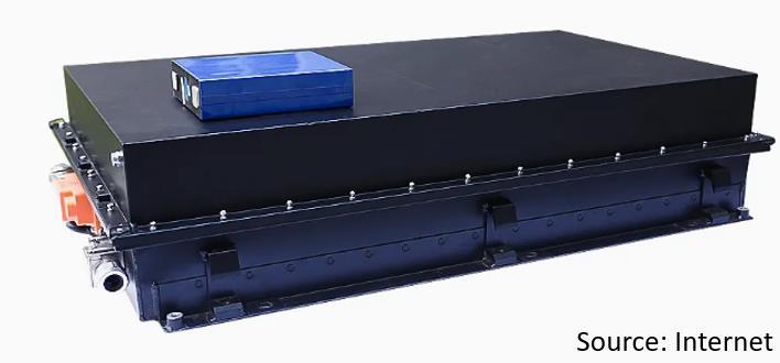
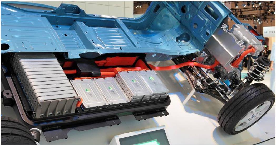
Batterycapacityunderconsiderationis60-65KWh&batterypackweightrangeis180-210kg.
VehicleConfigurationisFrontAxleDriven,4X2,WithE-axleConfiguration.
International Research Journal of Engineering and Technology (IRJET) e-ISSN: 2395-0056
Volume: 13 Issue: 03 | Mar 2026 www.irjet.net p-ISSN: 2395-0072
2.2 Vehicle Selection and Conversion
VehicleCo-OrdinateSystem(VCS)isdefinedasperindividualvehicleCADenvironmentrequirements. Ingeneral,belowSchemeshowsVCSPositionandVehicleDirections.
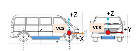
Fig 3:VehicleCo-OrdinateSystem(VCS)andVehicleLevelDirection
International Research Journal of Engineering and Technology (IRJET) e-ISSN: 2395-0056
Volume: 13 Issue: 03 | Mar 2026 www.irjet.net p-ISSN: 2395-0072
TheDMU(DigitalMockUp)studycarriedoutforvariousbatterypacksizesapplicableforsaidapplication. TheeachbatterypacklocationStudyinvolved,
ImpactonvehicleC.G,
VehicleWeightsDistribution
AccessibilityandServiceability
Packagingconstraintsduetosurroundingaggregates Evaluationstudyforvariouslocationsdescribedbelow–
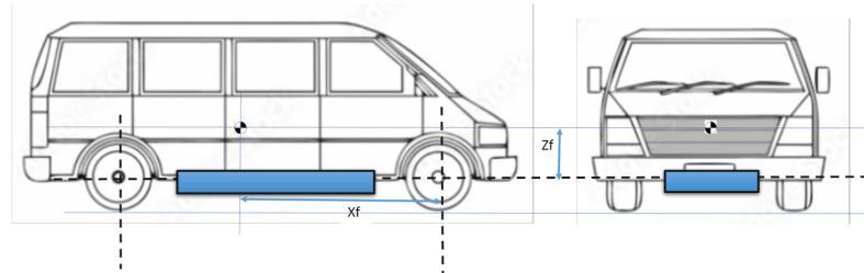
The battery was placed between the front & rear axles approximately at center of vehicle wheelbase. At said locations importantparameterevaluatedareVehicleGroundClearances,VehicleRampOverangle,andNecessaryprotectionneeded againststonehitting,WaterSplashingandMudAccumulationpossibilityinadditiontotheoneslistedabove.
Thebatteryplacementwasdonesuchasgroundclearanceleastimpacted.ComparedtoitsICEvariant.Thelayout1isshownin fig4
Inthislayoutbatterywasmountedattherooftopofthevehicle.Thiswasdoneasitwaseasytomountwithminormodifications onbody.Additionally,thebatterycoversweredesignedforaestheticallyandaerodynamicconsiderationsasitwascompletely visiblefromoutside.Thelayoutisshowninfig5
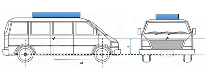
Based on the technical analysis, the height of the C.G increases in this layout which impacts vehicle dynamic manoeuvre capability.
International Research Journal of Engineering and Technology (IRJET) e-ISSN: 2395-0056
Volume: 13 Issue: 03 | Mar 2026 www.irjet.net p-ISSN: 2395-0072
Anewlocationwasselectedtomountthebatteryatrearsideofvehicle.Themodificationrequiredtoelevatethefloor.Elevated floorimpactstheheadroomforrearseatingpassenger.Thesepositionalsocallsforminimummodificationinsurrounding layout.
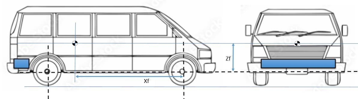
Technicalanalysisindicates,theC.Gwillreducecomparedtorooftopmountingbutwillaffectthegrade-ability.Packagingatthe rearsidewillhavetheriskofdamagingthebatteryduetorearendcrashfromfollowingvehicle.
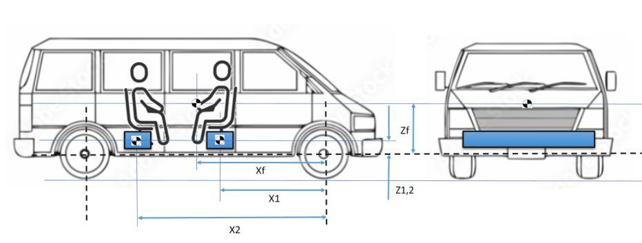
Layout 4: – Battery placement – Mounted Inside cabin below Seats.
Batterywasplacedinsidethecabinunderthepassengerseats.Theadvantagehereisthatbatterywillbesafefromhittingthe road,bumpers,etc.ascomparedtootherplacementsandwillhavelowC.G.Splitbatteryproposalcanalsobeusefultoimprove thebatterycapacityandvehiclerange.
4. Vehicle C.G and Load Distribution Calculations Methodology:
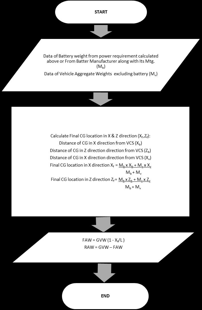
Below Flow chart helps to understand and calculate the Vehicle C.G Calculation with all the aggregates in place, Load distributiononFrontAxleandRearAxleinLadenandUn-ladencondition.
Thiscalculationprocessiscarriedoutforall4layoutsdiscussedabovetostudytheimpactofBatteryPackPlacementsOn VehicleC.GandLoadDistribution.
Thecalculationsforall4layoutsweredoneasperflowchartbelow–
International Research Journal of Engineering and Technology (IRJET) e-ISSN: 2395-0056
Volume: 13 Issue: 03 | Mar 2026 www.irjet.net p-ISSN: 2395-0072
International Research Journal of Engineering and Technology (IRJET) e-ISSN: 2395-0056
Volume: 13 Issue: 03 | Mar 2026 www.irjet.net p-ISSN: 2395-0072
Variouslayoutsstudiesdoneinearliersectionshavecertainbenefitsandcertainlimitations.AdditionalstudyofCGand Loaddistributionhaddeepenedtheinsightsaboutthedynamicsofthevehicleandpackagingbenefitsandlimitations aboutaparticularlayout.
Battery placement –Between Chassis Structure
Battery placement –Mounted on rooftop
Pros
Lowerscentreofgravity(CG)
BetterweightdistributioninvehicleFAW andRAW.
Goodtractionatall4wheels
Good thermal management and crash protection
Simplifiedhigh-voltage(HV)wiring.
Easytomount
Easeofaccessibility
No intrusion of BIW inside cabin for accommodatingthebatterypack.
IncaseofFireincidents,rescuecanbeeasy
Coolingsystempackagingwillbesimple.
Weight distribution is better with this layout.
Cons
Ground Clearance and Vehicle Ramp Over angle may get compromised.
IntrusionmightbeneededinBIW for accommodating the battery pack
Vehicle CG point shifted in Zdirection resulting in increase in Vehiclerollovertendency.
ResultsinincreaseofvehicleDrag Force.
Requires heavy structure at the top of the vehicle to sustain batteryload.
HV cable routing will be lengthy resultinginhighercostimpact.
Battery placement – At BIW End (Below Last Row Seat)
BIWlayoutisopenforbetterutilizationof seatinglayout.
LOWfloorheightatcenterportioncanbe possible.
IncaseofFireincidents,rescuecanbeeasy
Harness routing for HV cable will be simplerandoptimized.
Layout is better suitable for Rear Wheel Driveoption.
Considerablereductioninvehicle tractive force front wheel due to shiftofC.GawayfromFrontAxle.
Affectscrashsafety,fromRear
To meet Departure angle requirement,rearfloorneedtobe lifted quite up in Z direction. Resulting in Reduces headroom forrearseats.
Battery damage in case of Crash from Rear may affect its life and furtherusability
Battery placement –Mounted Inside cabin below Seats.
Efficientspaceutilization.
Lowerscentreofgravity(CG)
BetterweightdistributioninvehicleFAW andRAW.
Good thermal management and crash protection
Simplified high-voltage (HV) and LV Routing.
LayoutisbetterutilizedforallWheelDrive option.
Serviceabilitywillbebitcomplex
IncaseofFireIncident,possibility ofoccupantsafetyiscritical.
Ground Clearance and Vehicle Ramp Over angles may get compromisedtosomeextent.
International Research Journal of Engineering and Technology (IRJET) e-ISSN: 2395-0056
Volume: 13 Issue: 03 | Mar 2026 www.irjet.net p-ISSN: 2395-0072
OutComeofthestudyistosharetheinsightsofvariouspossiblelayoutofbatterypackinsmallpassengervehicle.Theimpact ofbatterypackbeingoneofthehighestweightcontributoronvehicleC.Gandloaddistributionplaysavitalroleandcannotbe overlooked.
Eachlocationhasitsownbenefitsanddrawbacks,soitisimportanttofindabalanceofallbasedonapplicationoftheproduct. Saiddocumentwillcertainlyhelptoformthebasistoidentifyandworkoutthesuitablepositiontoendusers.
1.ShashankArora,AjayKapoor,WeixiangShen:ApplicationofRobustDesignMethodologytoBatteryPacksforElectric Vehicles:IdentificationofCriticalTechnicalRequirementsforModularArchitecture.
2.Ehsani,M.;Gao,Y.;Emadi,A.ModernElectric,HybridElectric,andFuelCellVehicles:Fundamentals,Theory,andDesign; CRCPress:BocaRaton,FL,USA,2009
3.GiovanniBelingardi,AlessandroScattina:BatteryPackandUnderbody:IntegrationintheStructureDesignforBattery ElectricVehicles ChallengesandSolutions
4.ChristopherKrüger,SebastianSpohr,DavidMerdivan,PeterUrban:Avoidingstructuralredundanciesbetweenthevehicle bodyandthebatteryhousingbasedonafunctionalintegrationapproach
5.ThomasD.Gillespie,FundamentalsofVehicleDynamics