
International Research Journal of Engineering and Technology (IRJET) e-ISSN: 2395-0056
Volume: 13 Issue: 03 | Mar 2026 www.irjet.net p-ISSN: 2395-0072
RESPONSE OF HIGH-RISE RC BUILDING WITH TRANSFER SLAB AND FRICTION DAMPERS UNDER INDEPENDENT TIME HISTORY DATAS
Rudramuni H R1 , Dr.Chethan K2 ,
1P.G. Student, Department of Civil Engg., Major: Earthquake Engineering, University of Visvesvaraya College of Engineering, Karnataka, India, 2Associate professor, Department of Civil Engg., University of Visvesvaraya College of Engineering, Karnataka, India
Abstract - This study investigates the High-rise reinforced concretebuildingsarehighlyvulnerabletolateralforcessuch as earthquakes and wind. The presence of transfer slabs introduces vertical irregularities that influence the dynamic response of the structure during seismic events. This study evaluatestheseismicperformanceofaG+20RCbuildingwith transfer slabs placed at different levels. Finite Element AnalysisiscarriedoutusingModalAnalysis,EquivalentStatic Analysis, Response Spectrum Analysis, and Time History Analysis. Models are developed with and without friction dampers and a central core shear wall. Key response parameters such as fundamental time period, base shear, storey displacement, storey drift, and acceleration are evaluated and compared according to IS 1893:2016 provisions.
Key Words: Modal analysis, Response spectrum analysis, Shear Wall, Peak ground acceleration
1. INTRODUCTION
High-rise buildings are tall multi-storey structures constructed to efficiently utilize limited urban land for residential,commercial,ormixed-usepurposes.Asbuilding height increases, structures become more susceptible to lateral loads such as wind and earthquakes. To maintain stabilityandsafety,effectivelateralload-resistingsystems arerequired.Transferslabsarecommonlyusedinhigh-rise buildings to redistribute loads where the column arrangementchangesbetweenfloors.Althoughtheyprovide architectural flexibility, transfer slabs introduce stiffness irregularities that influence seismic performance. Shear walls are widely used to improve structural stiffness and resist lateral forces. In addition, dampers are installed to dissipate seismic energy and reduce structural vibrations. The combined use of transfer slabs, shear walls, and dampers enhances the seismic resistance of high-rise buildings.Properstructuralanalysisisnecessarytoensure safety, serviceability, and efficient performance under earthquakeloading.
1.1 Classification of structural system
Thestructuralmodelsconsideredinthestudyareclassified basedonthelocationandcombinationoftransferslabsand
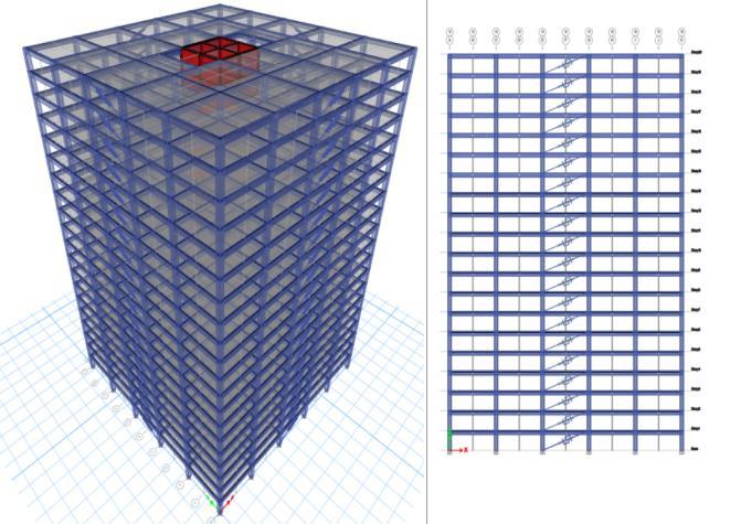
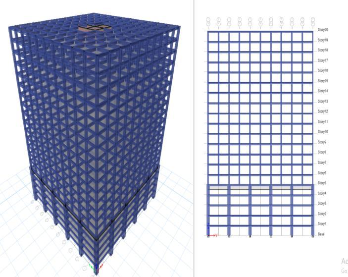
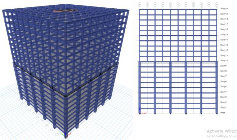
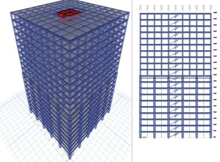
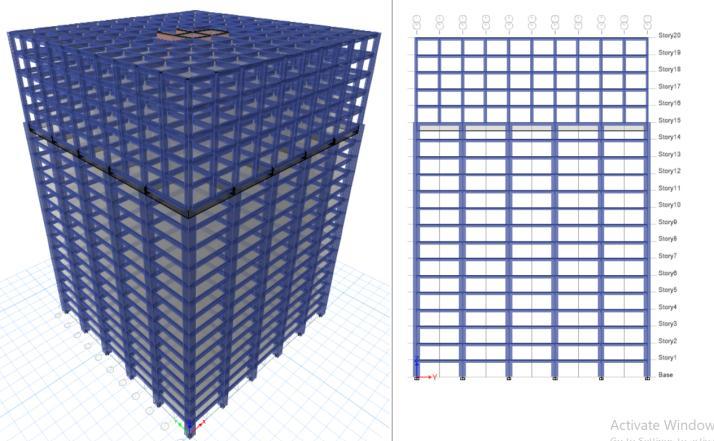
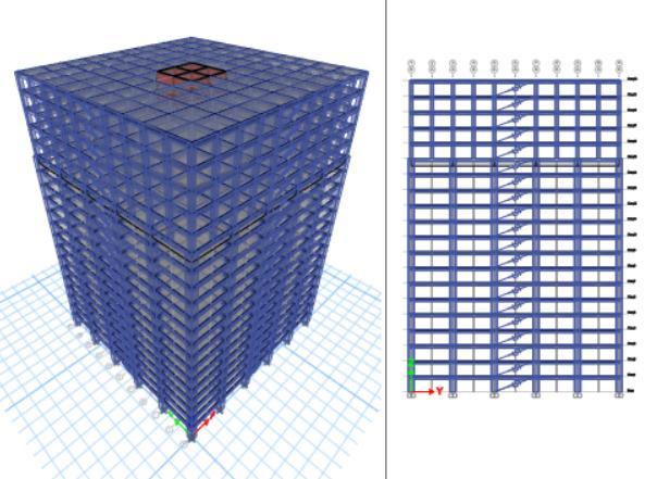
thebaseconditionofthebuilding.Fourmainconfigurations aremodelled:abuildingwithatransferslabatthe5thfloor (20DT5), and buildings with transfer slabs at 10th floors (20DT10), floors and 15th floors (20DT15). Each configurationisanalyzedundertwobaseconditions:fixedbaseandFrictionDamperssystems.Thisclassificationallows comparison of the influence of transfer slab location and Dampers on the seismic response of the 20-storey RCC building
1.2 Objective of the study
Thestudyaimstoinvestigatetheseismicperformanceofa high-risereinforcedconcretestructurewithatransferslab. It focuses on evaluating the effect of vertical mass and stiffnessirregularitiesintroducedbythetransferslabonthe structuralresponseduringearthquakes.ResponseSpectrum Analysis is carried out in accordance with IS 1893 to determine important parameters such as storey displacement, storey drift, base shear, and natural time period. In addition, nonlinear Time History Analysis is performedusingsuitableearthquakegroundmotionrecords to assess the dynamic behavior of the building. The study also examines the effectiveness of seismic dampers in reducingdisplacement,drift,acceleration,and baseshear. Finally,theresearchaimstoidentifytheoptimumlevel of the transfer slab with dampers that provides improved seismicperformanceandenhancedstructuralsafety.
2.PRELIMINARY DATA CONSIDERED FORANALYSIS
Building Models and Geometry
Thisstudyinvestigatestheseismic performanceofa G+20 high-risereinforcedconcretebuildingusingETABSsoftware byvaryingthepositionofthetransferslab.Thebuildinghasa totalheightof60mwithaplandimensionof40m×40m andconsistsof20storeys,eachwithauniformstoreyheight of3m.Thestructuralsystemincludesreinforcedconcrete beams, columns, slabs, and a central core shear wall extendingthroughoutthebuildingheighttoprovidelateral stiffness and stability. Transfer slabs are introduced at differentstoreylevelstocreatearchitecturalflexibilityand openspaces,resultinginverticalirregularityinthestructure. The transfer slab redistributes loads from discontinuous upper columns to supporting members below. Column
International Research Journal of Engineering and Technology (IRJET) e-ISSN: 2395-0056
Volume: 13 Issue: 03 | Mar 2026 www.irjet.net p-ISSN: 2395-0072
spacingabovethetransferslabismaintainedat4m,while belowitincreasesto8m.Thenormalslabthicknessis150 mm, whereas the transfer slab thickness is taken as 1500 mm.Toimproveseismicperformance,frictiondampersare installed up to the 10th floor in a zig-zag configuration at externalcorners.Thestructureissubjectedtoaliveloadof4 kN/m²andasuperimposeddeadloadof1.5kN/m².Seismic analysisisperformedaccordingtoIS1893:2016forZoneIV conditions.Modal,EquivalentStatic,ResponseSpectrum,and TimeHistoryanalysesarecarriedouttoevaluateparameters suchastimeperiod,baseshear,storeydisplacement,drift, andtopflooracceleration.abbreviationsinthetitleorheads unlesstheyareunavoidable.
Modeling Description
In all structural models, reinforced concrete is used for beams,columns,slabs,andshearwalls.Thegradeofconcrete adopted is M30 for beams, columns, and shear wall components, while Fe500 grade steel is used as reinforcement. Normal floor slabs are modeled with a thicknessof150mm,andthetransferslabismodeledwith 1500 mm as a deep slab with increased thickness to effectivelytransferloadsfromdiscontinuousuppercolumns tolowersupportingmembers.Thefloorslabsaredesignedto resist gravity loads and are assumed to act as a rigid diaphragm in the structural analysis, ensuring efficient transfer of lateral seismic forces to the vertical resisting elements. The entire structural system is modeled and analyzedinETABSinaccordancewithIS18932016part:1 provisiontoaccuratelycapturetheseismicbehaviorofthe building.
zeroandrotationisrestrained.Followingvalueshavebeen usedtomodelthedamper Non-lineardynamicanalysishasbeenperformedtostudy the effect of Friction Damper on seismic behavior of structure. Response spectrum function has been defined usingIS1893:2016foradampingof5%[14].
Table 3: Damper properties used in modeling
Table 3: Description of the Models and their Nomenclature
AsperIndianstandardcodeprovision,IS875(Part2)[19], Live Load considered are 4 kN/m2, Super Imposed Dead loadconsidered1.5kN/m2andIS1893:2016hasbeenused to define seismic load on the building with seismic zone factorZ=IV;ImportancefactorI=1;Responsereduction factorR=5,ExternalwallloadConsideredare12.648kN/m andInternalWallloadare6.324kN/m.
Properties of Friction Dampers
The Friction damper used in all models along one longitudinaldirectionandrestrainedinothertwotransverse directions, in its local coordinate system. Non linearity is consideredalongtheactivedirectionU1.Rotationalinertiais

International Research Journal of Engineering and Technology (IRJET) e-ISSN: 2395-0056
Volume: 13 Issue: 03 | Mar 2026 www.irjet.net p-ISSN: 2395-0072
International Research Journal of Engineering and
Volume: 13 Issue: 03 | Mar 2026 www.irjet.net
3. RESULTS AND DISCUSSION
3.1 TIME PERIOD
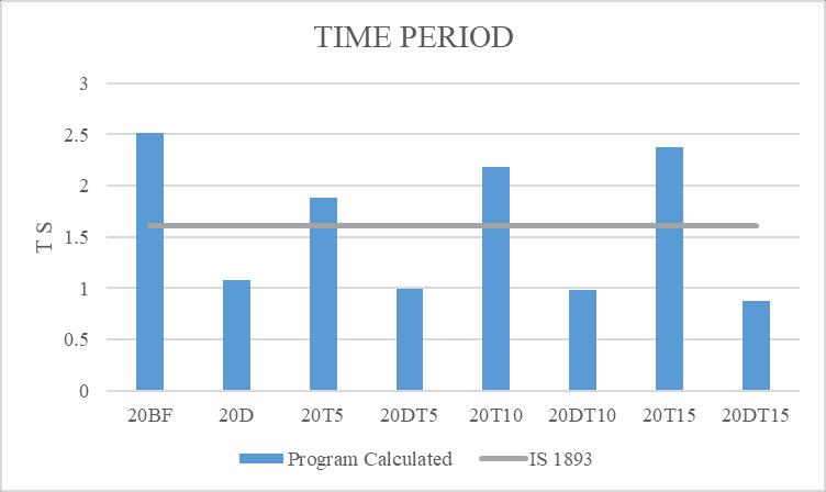
Thebasictimeperiodforallmodelsiscalculatedbycarrying out modal analysis based on the mass and stiffness characteristicsofthestructure.
TheFundamentalTimePeriodasperIS1893(Part1):2016, isgivenbythefollowingformula:
Ta=0.075h0.75 wherehisthebuildingheightinmeters.
Ta=0.075(60)0.75=1.61s
Thecomparisonoffundamentaltimeperiodsobtainedfrom modalanalysisandIScodevaluesispresentedinTable6.1, and the graph of models vs. time period is presented in Figure6.1
International Research Journal of Engineering and Technology (IRJET) e-ISSN: 2395-0056
Volume: 13 Issue: 03 | Mar 2026 www.irjet.net p-ISSN: 2395-0072
Table 6: Base Shear of Time history cases (in kN)
3.3 TIME HISTORY ANALYSIS
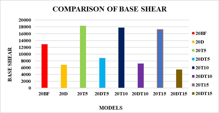
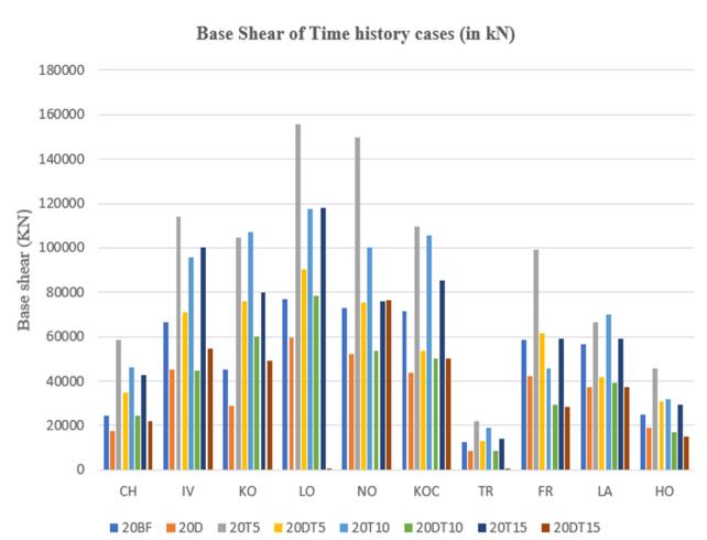
3.3.1 Base Shear
11: Comparison of Base Shear of all models (THA)
3.3.2 STOREY DISPLACEMENT
Table 7: Maximum roof displacement of all models
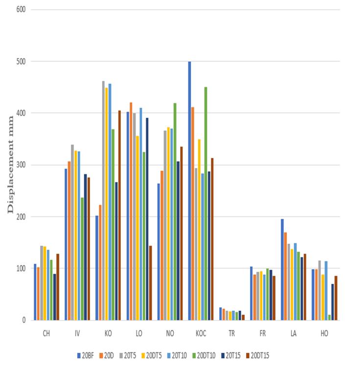
Figure 12: Comparison of Maximum roof displacement of all models (THA)
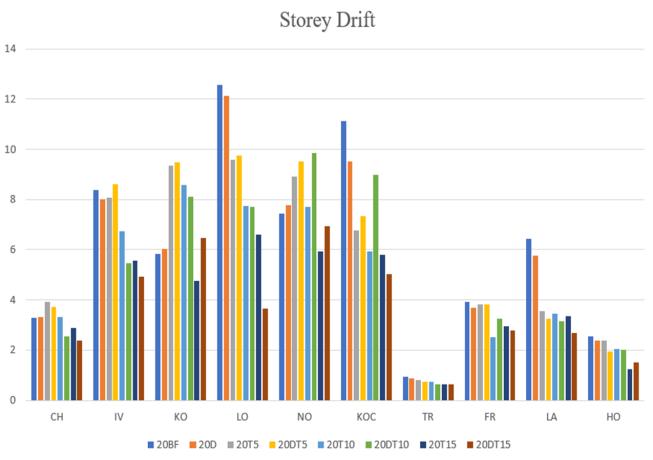
3.3.3 DRIFT RESULT OF TIME HISTORY ANALYSIS
Story drift is the lateral deflection from one storey to the nextwhenlateralLoadsAreApplied,expressedasaratio: Δ/h Check against Code limits of: H/400 to H/600, Limits exceededleadtostiffening.
Volume: 13 Issue: 03 | Mar 2026 www.irjet.net
Table 8: Comparison of Story Drift of all models, (THA)
3.3.4 MAXIMUM TOP FLOOR ACCELERATION
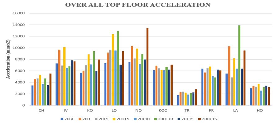
Maximumtopflooraccelerationisthepeakaccelerationat theroofofabuildingduringanearthquake.Itisimportant for evaluating possible damage to non-structural componentsintallbuildings.Duetohighervibrationmodes and response amplification, roof acceleration can become twotothreetimesgreaterthanthegroundacceleration.
Table 9: Maximum Top Floor Acceleration (mm/s2) of all models
3. CONCLUSIONS
Structural Period and Stiffness
The baseline model (20BF) demonstrates high flexibility, with a time period 56% higher than IS 1893 standards. Introducing fluid viscous dampers (20D) or higher-level transfer slabs significantly increases stiffness. The hybrid 20DT15configuration(15th-floorslabwithdampers)proves most effective, achieving a 65% reduction in time period, signalingmaximumstructuralstability.
Base Shear and Seismic Demand
There is a stark contrast between slab-only models and hybriddampermodels:
Slab-Only(20T5,20T10,20T15):Theseincreasebaseshear by34–120%,astheaddedmassofthetransferslabattracts higherseismicforces.
Hybrid Models: Combining dampers with transfer slabs dramatically mitigates this effect. The 20DT15 model reducesbaseshearbyapproximately68%instaticanalysis andupto94%intimehistoryanalysiscomparedtothebare frame.
Displacement and Inter-Storey Drift
20BF 3489 7288 5668 7319.4 7572.9 6104 1817 6374 5533 2975
20D 4548 9676 6022 9163.3 10306 6874 2297 5738 10266 3350
20T5 4687 6916 6957 9655.8 8135.1 6434 2389 6438 4880 3260
20DT5 5270 10101 8872 12375 9839.4 6161 2230 6759 8180 3758
20T10 3715 6546 7114 9542.7 7192.6
3407
The20BFmodelexhibitsthehighestdisplacementanddrift, particularlyunderintensegroundmotionslikeTRandLA. While lower-level slabs (20T5) are counterproductive increasingdriftbyupto40%duetostiffnessdiscontinuities shiftingtheslabhigher(20T15)improvesperformance.The 20DT15 remains the optimal setup, reducing top-storey displacementby56.4%.
Top Floor Acceleration
Unlike other parameters, top floor acceleration generally increaseswiththeadditionofdampers(by20–40%),asthey attractadditionalforcestotheupperlevels.Lowertransfer
International Research Journal of Engineering and Technology (IRJET) e-ISSN: 2395-0056
Volume: 13 Issue: 03 | Mar 2026 www.irjet.net p-ISSN: 2395-0072
slab placements (20T5) show erratic acceleration, while higherplacements(20T15)providemorestablebehavior. Conclusion
The analysis confirms that 20DT15 is the superior configuration.Byplacingthetransferslabatthe15thfloor and integrating dampers, the structure achieves an ideal balance of high stiffness, low base shear, and minimal displacement
REFERENCES
[1] BasavalingappaandAnilKumarB“AnalysisofHigh-Rise Building and its Behaviour Due to Shear Wall at Different Location and in Different Seismic Zones” International Journal of Engineering Research & Technology (IJERT), Volume: 9, Issue: 10, September 2020.
[2] ElawadyA.K,H.O.Okail,A.A.Abdelrahman,E.Y.SayedAhmed“SeismicBehaviourofHigh-RiseBuildingswith Transfer Floors” Electronic Journal of Structural Engineering,Volume:14,Issue:1,2014.
[3] HaoLi,ZhizhaoFang,YukunMa,JunjiaLyu,ZhiyuWang, Yongshan Zhang, Yanhui Liu “Seismic Response and FragilityAnalysisofTODMulti-Tower-PodiumBuildings with Thick Transfer Slabs” Structural Engineering International(IABSE),onlinearticle,March2025.
[4] MaheshMohanPardeshi,Dr.G.Manikandan“Studyof DifferentTypesofDampersatDifferentLocationUsedin High Rise Rigid Structure” International Research Journal of Engineering and Technology, Volume: 9, Issue:6,June2022.
[5] Mohammed Shoaib, Dr. A. Swetha “Non-Linear Pushover Analysis of RCC Framed Structure by ProvidingFluidViscousDampersatDifferentLocations” JournalofScientificResearchandTechnology,Volume: 1,Issue:9,December2023.
[6] SandraSureshandNajmaAnanthakumar“Comparative StudyonRegularandIrregularHigh-RiseBuildingswith Transfer Floors using Dampers (ETABS analysis)” International Journal for Research in Applied Science and Engineering Technology (IJRASET), Volume: 8, Issue:VII,July2020.
[7] Sinha A.K and Sharad Singh “Seismic Protection of Rc FramesUsingFrictionDampers”InternationalJournalof Civil Engineering and Technology (IJCIET), Volume 8, Issue5,May2017
[8] Yao Domadzra and Murtaza Hasan’s “International ResearchJournalofEngineeringandTechnology(IRJET), Volume:11,Issue:4,April2024.
[9] IS 800:2007 - General Construction in steel- code of practice.
[10] IS 1893:2016 (Part I) - Criteria for Earthquake resistant design of structure” for both RC and steel structure.
[11] IS875(PartIILiveLoads)1987-IndianStandardcode ofpracticefordesignloads(otherthanEarthquake)for buildingandstructures.