
International Research Journal of Engineering and Technology (IRJET) e-ISSN: 2395-0056
Volume: 13 Issue: 03 | Mar 2026 www.irjet.net p-ISSN: 2395-0072

International Research Journal of Engineering and Technology (IRJET) e-ISSN: 2395-0056
Volume: 13 Issue: 03 | Mar 2026 www.irjet.net p-ISSN: 2395-0072
Prerana Gaikwad1 , Kajal Bhilare2 , Chaitrali Gaikwad3, Pranali Sarak4 , Ms.K.H.Sakhare5 .
1,2,3,4 Student of Mechanical Engg. Karmveer Bhaurao Patil Poly. Satara, India
5 Lecturer,of Department of Mechanical Engg. Karmveer Bhaurao Patil Poly. Satara, India
Abstract - The objective of the project is to prepare a machine which cuts sheet metal without human efforts but operates pneumatically. Compressed air is used as working media. The compressed air moves the blades of machine to cut the sheet of metal. The idea of the project generated due to a manual sheet metal sheering machine in Shree Ganesh Industry. In that machine sheet metal is placed in between the two sheering blades of machine and the lever is pulled down to move the upper movable blade and cut the work piece. But in that machine large force is required between (30-40 kg)which can make tire to a worker who continuously works on it for mass production in large scale industry; so to reduce the human efforts pneumatic machine should chose. Hence for some development of machine, we have chosen this subject for our project. We hope that a good idea will develop and we can use it in many industries in surrounding and our practical knowledge, team working skill, leadership skills will be improved
Thisdocumentistemplate.Weaskthatauthorsfollowsome simpleguidelines.Inessence,weaskyoutomakeyourpaper lookexactlylikethisdocument.Theeasiestwaytodothisis simplytodownloadthetemplate,andreplace(copy-paste) thecontentwithyourownmaterial.Numberthereference itemsconsecutivelyinsquarebrackets(e.g.[1]). However the authors name can be used along with the reference number in the running text. The order of reference in the runningtextshouldmatchwiththelistofreferencesatthe endofthepaper.
1.1 Aim of Project:
Cuts sheet metal without human efforts, convert manual machinetosemi-automaticmachine.
1.2 Description of Project:
Theobjectiveoftheprojectistoprepareamachinewhich cuts sheet metal without human efforts but operates pneumatically. Compressed air is used as working media. Thecompressedairmovesthebladesofmachinetocutthe sheet of metal. The idea of the project generated due to a manual sheet metal sheering machine in Shree Ganesh Industry.Inthatmachinesheetmetalisplacedinbetween thetwosheeringbladesofmachineandtheleverispulled downtomovetheuppermovablebladeandcuttheworkpiece.Butinthatmachinelargeforceisrequiredbetween (30- 40 KG)which can make tire to a worker who
continuouslyworksonitformassproductioninlargescale industry;sotoreducethehumaneffortspneumaticmachine shouldchose.Henceforsomedevelopmentofmachine,we havechosenthissubjectforourproject.Wehopethatagood idea will develop and we can use it in many industries in surrounding and our practical knowledge, team-working skill,leadershipskillswillbeimproved.
DCvalveisatlefthandpositionasshowninfigure.Thecap endport&pressureportgetconnectedtoeachotherandthe rod end port gets connected to the exhaust port. The compressed air comes in the cap end of the cylinder and pushesthepistonsoutwards.Theairalreadypresentinthe rodendsideispushedoutofthecylinder.
2.1 Problem Statement:
Itisdifficultforaworkertouseforceonamachineand dothesamethingalongtime.Tosolvethisproblem,thefoot operated machine was converted pneumatically operated. Manual cutting machines are not suitable for bulk cutting processeswithaccuracy.
2.2 Objectives:
➢ To prepare a machine which cuts sheets metal without humaneffortsbutoperatespneumatically.
➢ Massproductiontechniquescanbeadoptedtoproduce pneumaticsystem,whichnotonlysavemoneybutsavetime too.
➢ Theairisusedinpneumaticdevicesisdriedandfreefrom moisture so that it does not create any problem to the internalpartsofthesystem.
➢ Asmostofthepneumaticdevicesareairbased,theyhave alesscomplicateddesign.
➢ Pneumaticactuatorsalsohavelonglifeandperformwell withnegligiblemaintenancerequirementthroughouttheir lifecycle
2.3 Block diagram:
Thepneumaticmachineincludesatablewithsupportarmsto holdthesheet,stopsorguidestosecurethesheet,upperand lower straight - edge blades, a gauging device to precisely position the sheet. The table also includes the two-way directionalvalve.Thetwo-waydirectionalvalveisconnected to the compressor. The compressor has a piston for a movablemember.Thepistonisconnectedtoa crankshaft,
International Research Journal of Engineering and Technology (IRJET) e-ISSN: 2395-0056
Volume: 13 Issue: 03 | Mar 2026 www.irjet.net p-ISSN: 2395-0072
whichisinturnconnectedtoaprimemover(electricmotor, internalcombustionengine).Atinletandoutletports,valves allow air to enter and exit the chamber. When the compressor is switched ON, the compressed air is flow to inletofthepneumaticcylinder.Thesheetisplacedbetween the upper and the lower blade. The lower blade remains stationary while theupperblade isforced downward.The upper blade is slightly offset from the lower blade, approximately5–10%ofthesheetthickness.Also,theupper bladeisusuallyangledsothatthecutprogressesfromone endtotheother,thusreducingtherequiredforce.Afterthe materialiscut,adjustthepneumatichandlevertothemid position (i.e., normal position) and then the compressor is switchedOFF.Thefollowingfigureshowsgenerallayoutfor themachine.
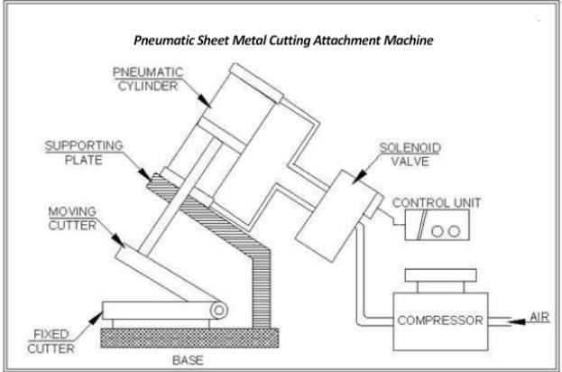
Now we know that Pneumatic sheet metal cutting attachmentmachineisverycheapascomparedtohydraulic shearingmachine.Therangeofthecuttingthicknesscanbe increasedbyarrangingahighpressurecompressorandthis machine is advantageous to small sheet metal cutting industries as they do not have rely on the expensive hydraulic shearing machine. By using this machine productiontimeisdecreaseandgetaccuratebyproductalso thismachinewhenmachineinworkingthattimenoneedof workercontinueforoperatingtothismachine
ThroughFRLunitaircanbecontrolled.Fromthemanifolda separate supply for the machine is taken out and given to initially the air-compressor is started and allowed the receivertankairpressuretoreachupto8bars.Thesupply air is then passed to the manifold ONOFF switch; so as to operatethemachineatwillwithoutinterruptingtherunning ofcompressor.Thenthepipecarriescompressedairfirstto machinesDirectionControlValve.Atposition„A‟showsthe non-actuatedcircuitdiagrams.Atthispositionthepistonis steady and locked. All ports are in closed condition at position„B‟,theDCvalveisatlefthandpositionasshownin figure. The cap end port & pressure port get connected to eachotherandtherodendportgetsconnectedtotheexhaust port.Thecompressedaircomesinthecapendofthecylinder andpushesthepistonsoutwards.
Wewouldliketoexpressourdeepandsinceregratitudeto my Guide Ms. K. H. Sakhare Department of Mechanical Engineering,forguidingustoaccomplishthisprojectwork. Itwasourprivilegeandpleasuretoworkundershe’sable guidance.Weareindeedgratefultoherforprovidinghelpful suggestion, from time to time. Due to he’s constant encouragementandinspirationweareabletopresentthis project.AtthisjunctureIfilldeeplyhonouredinexpressing my sincere thanks to Mr. Vikas B. Jadhav for giving us opportunityandsponsorshipfortheprojectandMr.Omkar A.Khairmodeforguidingustoaccomplishthisprojectwork and for making the resources available at right time and providing valuable insights leading to the successful completionofourproject.Weexpressedourdeepgratitude to Mr. Sameer S. Yewale, Head of Mechanical Engineering Department, for his valuable guidance and constant encouragement, we are very much thankful to Mr. B. V. Kadam, Principal, Rayat Shikshan Sanstha’s, Karmveer Bhaurao Patil Polytechnic, Satara for providing all the necessaryfacilitiestocarryoutprojectwork.Lastbutnotlist we are thankful our parents for their moral as well as financial support authors can acknowledge any person/authoritiesinthissection.Thisisnotmandatory.
[1]MadhuKumarV“DesignandFabricationofPneumatic Sheet Metal Cutting and Bending Machine. International JournalofEngineeringResearchAndAdvancedTechnology (IJERAT).
[2] Vishal Tambat, Nilkanth Rane, Omkar Savant, 4Pankaj Yadav.PneumaticShearingandBendingMachine,IJRRCME, Vol.2,Issue1,pp:(9-18),Month:April 2015 – September 2015.
[3] Aniruddha Kulkarni, Mangesh Pawar “Sheet Metal Bending Machine. IJIERT, I SSN: 2394-3696 VOLUME 2, ISSUE3,March.-2015
[4]Li,T.C.,Wu,H.W.,Kuo,M.J.:Astudyofgaseconomizing pneumaticcylinder.JournalofPhysics:Conferenceseries48,
International Research Journal of Engineering and Technology (IRJET) e-ISSN: 2395-0056
Volume: 13 Issue: 03 | Mar 2026 www.irjet.net p-ISSN: 2395-0072
1227–1232 (2006). Beater, P.: Pneumatic Drives: System Design,ModellingandControl.Springer,Berlin(2007).
BIOGRAPHIES


2nd

PreranaShivajiGaikwad
KajalDnyandevBhilare.
ChaitraliHanumantGaikwad.

4th 3rd Author Photo

PranaliTatyabaSarak.
Ms.K.H.Sakhare
© 2026, IRJET | Impact Factor value: 8.315 | ISO 9001:2008 Certified Journal |