
International Research Journal of Engineering and Technology (IRJET) e-ISSN: 2395-0056
Volume: 13 Issue: 02 | Feb 2026 www.irjet.net p-ISSN: 2395-0072
International Research Journal of Engineering and Technology (IRJET) e-ISSN: 2395-0056
Volume: 13 Issue: 02 | Feb 2026 www.irjet.net p-ISSN: 2395-0072
Fatima Tanveer1 , Aqeel Haider2
1School of Material Science and Engineering, Northwestern Polytechnical University, Xi’an, China 2School of Civil Engineering, Northwestern Polytechnical University
Abstract - Thisworkpresentsacomprehensivenumerical investigation of liquid-cooled cold plates designed for high heat-flux electronic applications. Five internal geometries, leaf-vein, rectangular, diamond, cylindrical, and triangular pin-fins, are systematically compared under identical boundary conditions to isolate geometric effects on thermal–hydraulic performance. Conjugate heat transfer simulations are performed using two substrate materials, aluminum and C1020 copper, and two coolants, PG25 and HFO-1336mzz(Z). Key metrics including temperature distribution, thermal resistance, and pressure drop are evaluated and validated through mesh independence and energy balance checks. A p-Norm-based multi-objective analysisidentifiestherectangularpin-finconfigurationwith PG25andC1020astheoptimalbalanceddesign.
Keywords: Thermal–hydraulic performance, Pin-fin geometries, multi-objective optimization, Liquidcooled cold plates
The continuous miniaturization of electronic devices, coupled with rising power densities, has created increasing challenges for thermal management. As components become smaller and more powerful, the heat generated per unit rises, leading to reliability issues and reduced efficiency if heat is not effectively dissipated. Conventional approaches such as forced air cooling and liquid cooling have been widely adopted, but these methods often lack the efficiency, durability, and scalability required for next-generation applications. Localized hotspots and uneven temperature distribution remain persistent challenges in high-performance systems.
Effective thermal management has therefore emerged as a critical enabling factor for next-generation electronic systems, directly influencing efficiency, safety, and longterm stability. Traditional cooling strategies that once satisfied earlier generations of electronics are now being pushed to their operational limits, prompting an urgent need for advanced heat dissipation solutions capable of addressing localized hotspots, transient heat fluxes, and strictsize and weightconstraints. Withinthiscontext, the present study is motivated by the growing demand for compact, passive, and high-performance thermal
management architectures that can sustain stable operation under increasingly severe thermal conditions, thereby laying the foundation for the exploration of capillary-based and structure-optimized cooling systems asviablealternativestoconventionalapproaches.
Recent innovations in thermal management aim to overcome these shortcomings. For example, nanoengineered two-phase cooling systems [1] have demonstrated enhancedheatdissipation and reliability in compact electronics. Similarly, advanced cooling techniques such as liquid cold plates and thermosiphon heat sinks provide scalable solutions for high-power devices. These developments highlight the urgency of transitioning from conventional thermal management systemstowardmoreadvancedandadaptablestrategies.
Building on these advancements, researchers are now focusing on structures that combine high thermal conductivity materials with optimized fluid pathways to further enhance heat spreading and reduce localized temperature peaks. Hybrid systems that integrate porous media, microchannels, pin fins or engineered capillary networks have shown the ability to stabilize temperature fluctuationsevenunderrapidlychangingheatloads.These designsimprove bothuniformityandtransport efficiency, allowing the coolant to reach and remove heat from critical regions more effectively than traditional straightchannel or fin-based layouts. Pin-fin topologies provide more manufacturing flexibility and controllability than strict biomimetic design, enabling systematic comparison across many geometric configurations. Capillary-based coolingsystemsofferapromisingpassivethermalsolution by utilizing wick-like structures and optimized flow pathways, such as biomimetic leaf-vein networks, to enhanceheattransferandmitigatehotspots formation[2] Biomimetic cooling designs, particularly diamond-shaped pinfins,havebeenshowntooutperformothergeometries in both heat transfer and flow efficiency, offering a promising solution for high-power thermal management.[3]
Biomimetic cooling systems, particularly those using diamond-shapedpinfins,effectivelybalancesuperiorheat transfer against manageable flow resistance. This geometry-based optimization is critical for enhancing thermalperformanceincompactelectronics.[4][5]
International
Volume: 13 Issue: 02 | Feb 2026 www.irjet.net p-ISSN: 2395-0072
Integrating these optimized structures with capillarydriven flow and phase-change materials creates adaptive, high-efficiency thermal pathways. This synergistic approach significantly outperforms traditional cooling methods, offering a robust solution for next-generation thermalmanagementunderhighheatloads.[6][7][8]
Aluminum's superior machinability enables the fabrication of intricate, porous channels that mimic biomimetic vein networks, enhancing capillary flow and thermal uniformity under high heat loads. This geometric adaptability, combined with its favorable conductivity-toweightratio,makesitidealfornext-generationcoldplates. Future advancements will integrate these passive, optimized structures with active cooling methods to manageincreasingpowerdensitiesincompactelectronics. [9][10][11]
Pin-fin geometry directly dictates the thermal-hydraulic trade-off: diamond shapes enhance heat transfer, while streamlined designs reduce flow resistance, highlighting shape optimization as a critical design lever. [12] Pin-fin geometrydirectlydictatesthethermal-hydraulictrade-off, with square fins enhancing heat transfer and circular fins minimizingflowresistance.Optimalperformancedepends onscaleandflowconditions,wheremicrometerfinsexcel at low Reynolds numbers and millimeter fins perform betterunderhighflowrates.Hybridpin-finarrangements offer a promising pathway to balance these competing objectivesforadvancedelectroniccooling.[13],[14],[15]
Pin-fin spacing and arrangementcriticallyaffect thermalhydraulic performance, where staggered layouts enhance heat transfer but increase pressure drop. Optimal geometry and advanced coolants like nanofluids can significantly improve overall system efficiency. [16], [17], [18]Microchannelheatsinksarevitalfordissipatinghigh heat fluxes in modern electronics. Their performance is influencedbychannelgeometry,coolantselection,andthe use of nanofluids. This study specifically examines how pin-fin arrangement and volume fraction affect heat transfer and pressure drop, with staggered layouts enhancingcoolingatthecostofincreasedflowresistance. [19][20] Quantitativeevaluationof finshapesshowsthat drop-shaped pins achieve the best thermal performance with the lowest thermal resistance, while circular fins provide efficient heat transfer pathways. These findings underscore that geometric optimization is critical for balancing thermal efficacy and hydraulic efficiency in advancedthermalmanagementsystems[21][22]
Micro heat sinks achieve optimal performance through geometry-specificdesign,whereI-shapedpinfinsenhance heat transfer while minimizing pressure drop by optimizingdimensionsandorientation.Validationthrough numerical and experimental methods confirms the governing equations and provides reliable local and average performance data across varying operating conditions. [23] [24] [25] Employing a 3D conjugate heat
transfer model that was verified by experiments, the laminar flow and conjugate heat transfer effect on microchannel heat sinks was investigated. The exact temperature distribution, heat transport patterns, and cooling efficiency are shown by the results.[26] Rectangular, trapezoidal, and triangular microchannels are investigated numerically in this work, which demonstrates that rectangular channels provide the best overall performance while high aspect ratio and higher channel number lower thermal resistance but increase pressure drop.[27] Single-phase convective heat transfer and flow properties are strongly influenced by microchannelshape. Heattransferandpressuredropare empirically correlated with aspect ratio and hydraulic diameter spacing for optimal laminar and turbulent performance.[28]
Accordingtorecentresearch,biomimeticcoolingdesigns inspired by leaf veins greatly improve thermal-hydraulic performance. When tuned using nanofluids and surface alterations, composite bionic microchannels that combine vein-like fractal routes with honeycomb features demonstrate significant improvements in heat transmission, reaching up to a 64.5% increase in Nusselt number. Similar to this, leaf-vein and tree-root-inspired liquid-cooled plates use multi-objective optimization and structured flow distribution to reduce pressure drop, enhanceuniformity,andlowerpeaktemperatures.[29,30]
Nature-inspired flow topologies successfully reduce hydraulic penalties and nonuniform heating, according to recent biomimetic cooling experiments. Leaf-vein-based channel growth techniques dynamically adjust to hotspot locations, reducing overall pressure drop while achieving a peak temperature reduction of up to 40 K and significantly enhanced temperature uniformity. Similarly, in terms of temperature management and pressure loss, bionic leaf-vein liquid-cooled plates for battery systems routinely perform better thanserpentine designs. Beyond vein networks, biomimetic surface patterns like microfeaturesinspiredbysharkskinfurtherimproveheat transmission by modifying flow mixing and boundarylayer behavior, illustrating the wide potential of biomimicry for sophisticated thermal management.[31,32,33]
Bionic spider-web-inspired cold plates enhance thermal managementinPEMfuelcellsandlithium-ionbatteriesby improvingtemperatureuniformityandreducinghotspots CFD and numerical simulations show optimized channel widths and angles increase cooling efficiency, lower pressure drop, and mitigate thermal risks, demonstrating superior performance over traditional serpentine designs while maintaining operational stability.[34], [35] Biomimeticcoolingsystemsdrawinspirationfromnatural transportnetworksthatachieveefficientflowdistribution understrictenergyandmaterialconstraints.Byemulating optimal branching found in vascular and venation
International Research Journal of Engineering and Technology (IRJET) e-ISSN: 2395-0056
Volume: 13 Issue: 02 | Feb 2026 www.irjet.net p-ISSN: 2395-0072
systems, these designs enhance coolant delivery and heat dispersal, reducing hotspots and improving temperature uniformity in high-heat-flux devices. Studies show that leaf-vein, spider-cobweb, sharkskin, snowflake, and fractal-inspired structures significantly improve thermalhydraulic performance, balancing heat transfer enhancement with pressure drop and manufacturability considerations. Bio-textured surface modification of straight-fin heat sinks is numerically and experimentally analyzed to enhance thermal performance without increasing size or weight. The textured fins demonstrate over 26% temperature reduction, ~34% lower thermal resistance, and a 21–40% increase in heat-sink effectiveness, particularly suitable for high-power electronicdevicessuchasCPUsandGPUs.[36]
Thermal system performance is significantly improved by incorporating sophisticated diagnostic methods and structural changes. The necessity of exact geometric control in dynamic thermal management has been confirmedbyinfraredthermographyinvestigationofplate heat exchangers, which has shown that flow arrangement directly controls transient temperature propagation and total heat transfer efficacy [37]. Another study employs two contrasting coolants to establish a comprehensive performance baseline. PG25, a conventional 25% propylene-glycol-water mixture with well-documented properties, provides a reliable reference for thermalhydraulicbehaviorincompactsystems.[38]
We developed a three-dimensional, steady-state, conjugate heat transfer model to simulate the thermalhydraulic performance of a liquid-cooled cold plate. Our approach consisted of four key phases: mathematical formulation, geometric definition, numerical solution, and verification.

Fig- 1:Numericalframework
Wemodeledthefluidflowasincompressibleandlaminar usingthecontinuity,Navier-Stokes,andenergyequations. Forthesoliddomains(baseplateandfins),wesolvedthe steady-state heat conduction equation. We enforced continuity of temperature and heat flux at all solid–fluid interfaces. We treated the working fluids as Newtonian with constant thermo-physical properties and neglected radiation,buoyancy,andphasechangeeffects.
Wedesignedthecoldplatewithfixedouterdimensions:a base plate measuring 100 mm × 70 mm × 5 mm and an internal flow cavity of 80 mm × 65 mm × 3 mm. We investigated five internal fin architectures, each with a constantfinheightof3mm:abio-inspiredleaf-veindesign and four uniform pin-fin arrays (rectangular, diamond, cylindrical, and triangular cross-sections). For the pin-fin arrays, we maintained a constant pitch of 3 mm × 3 mm andfindensity.
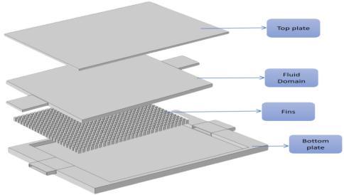
Fig- 2:Cutawayviewofthecoldplategeometrywith internalcavityandfinregion
We selected two solid materials, aluminum (k = 205 W/m·K) and C1020 copper alloy (k = 390 W/m·K), and two coolants, PG25 and HFO-1336mzz(Z), resulting in 20 simulationcases(5geometries×2materials×2coolants)
Table-1: Thermo-physicalpropertiesofmaterialsusedin simulation
International Research Journal of Engineering and Technology (IRJET) e-ISSN: 2395-0056
Volume: 13 Issue: 02 | Feb 2026 www.irjet.net p-ISSN: 2395-0072
As shown in Table 1, the selected materials and coolants provide a clear contrast in thermal conductivity and viscosity, enabling the isolation of their effects on conjugateheattransferperformance.

Fig- 3:Geometrystructureofallthetypesoffins(a) cylindricalpinfins,(b)diamond-shapedpinfins,(c) rectangular-shapedpinfins,(d)leaf-veinfinstructure,(e) triangularshapedpinfinstructure
We discretized the computational domain with an unstructured tetrahedral mesh and applied local refinement at solid–fluid interfaces and boundary layers. We performed the simulations using COMSOL Multiphysics software, employing a pressure-based segregated algorithm with the simple scheme for pressure–velocity coupling. We used second-order discretization for momentum and energy equations. We appliedthefollowingboundaryconditions:
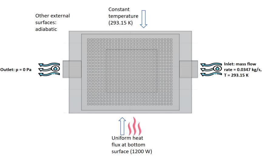
Thermal: We imposed a uniform heat flux of 171,428.6 W/m² (1200 W total) on the bottom surface of the base plate.Weheldthetopsurfaceataconstanttemperatureof 293.15 K and treated all other external surfaces as adiabatic.
Flow: We set a constant mass flow rate of 0.0347 kg/s at 293.15Kattheinletanddefinedtheoutletasa pressureoutlet(0Pagauge).
We considered the solution converged when scaled residuals for all equations dropped below 10⁻⁶ and key global monitors (maximum temperature and pressure drop)stabilized.
We conducted a grid independence study on two representative geometries: the rectangular pin-fin and leaf-vein designs. We tested three mesh densities and selected the medium mesh, which produced less than 1% variationinaverage base temperatureand pressuredrop. To validate the model physically, we compared the simulatedtemperatureriseacrossthesoliddomainwitha one-dimensional analytical conduction solution. The results showed consistent trends with deviations under 8 K, which we attribute to three-dimensional conduction and conjugate effects. We estimate the overall numerical uncertaintytobewithin±3%
We present the thermal-hydraulic performance of five cold-plate fin architectures (leaf-vein, rectangular, diamond, cylindrical, and triangular pin-fins) using two solidmaterials(Al,C1020)andtwocoolants(PG25,HFO). Results were derived from 20 validated, steady-state conjugateheattransfersimulations.
Table-2:SummaryofThermal-HydraulicPerformancefor AllConfigurations
Fig- 4:Boundaryconditions
International Research Journal of Engineering and Technology (IRJET) e-ISSN: 2395-0056
Volume: 13 Issue: 02 | Feb 2026 www.irjet.net p-ISSN: 2395-0072
This table consolidates the key performance metrics, enabling direct comparison of the trade-off between thermal resistance and hydraulic penalty across all tested geometry-material-coolantcombinations.
Our model was verified via mesh independence, confirming less than 1% variation in key outputs. We validatedthethermalsolutionbycomparingthesimulated temperature rise (ΔT_CFD) against a 1D analytical conduction estimate (ΔT_Analytical). CFD results were consistently higher (by 3–8 K) due to captured 3D and convective effects, confirming physical consistency. The lowest thermal resistance (0.01217 K/W) was achieved with the diamond pin-fin, C1020, and PG25, demonstrating superior heat spreading. In contrast, triangular and leaf-vein geometries showed higher thermalresistanceduetoflowmaldistribution.
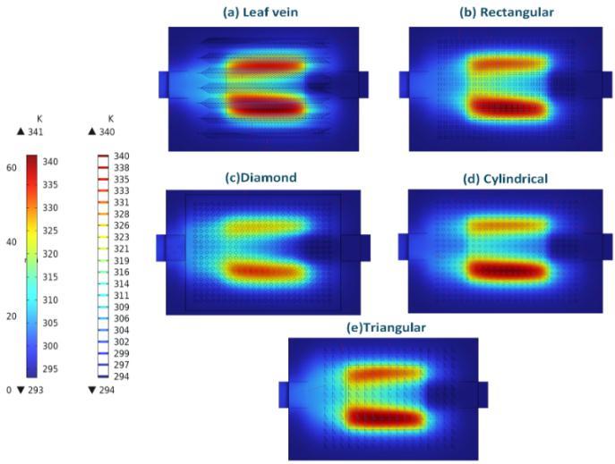
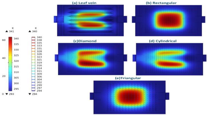
Hotspots correspond to areas of flow stagnation or reduced velocity, often found at channel bends or in the core heated zone. Diamond and rectangular geometries demonstrate superior thermal spreading, confining hotspots to smaller, cooler regions, while the leaf-vein design shows pronounced hotspots at its branching junctions due to uneven flow distribution. Coolant selectionfurthermodulatesintensity,withPG25providing smoother gradients than HFO, which exacerbates local heatinginhigh-resistancegeometries,directlylinkingflow physicstotheobservedthermalresistancetrends.
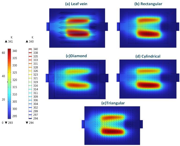
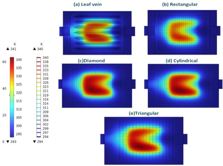
8:TemperaturecontoursofallgeometriesofC1020 forHFOcoolant
To provide a consolidated overview of the thermalhydraulic performance, all results are summarized in a single performance matrix (Fig-8). This graph plots thermal resistance against pressure drop for all 20 simulation cases, clearly delineating the performance trade-off between all the geometries, materials, and both
International Research Journal of Engineering and Technology (IRJET) e-ISSN: 2395-0056
Volume: 13 Issue: 02 | Feb 2026 www.irjet.net p-ISSN: 2395-0072
the coolants. This visualization encapsulates the principal finding of this study that while geometry dictates the fundamental performance cluster, material and coolant selectionactascriticalmodifierswithinthatdesignspace.
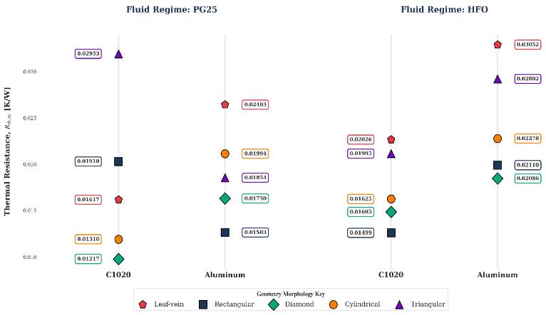
Fig- 9:ComparisonofThermalResistancePerformanceof PG25andHFOCoolants
Pressure drop was strongly geometry-dependent. The leaf-vein design imposed the highest penalty with PG25 (ΔP≈164Pa),whilediamondandtriangularpin-finswere most hydraulically efficient (ΔP < 10 Pa). Coolant choice criticallymodulated this behavior:HFO reduced ΔP in the complex leaf-vein channels by ~60% but caused severe penalties (ΔP > 100 Pa) in diamond/cylindrical pin-fins with aluminum substrates due to conjugate thermalviscous effects. Velocity field visualizations confirmed thesetrends,showinguniformflowinlow-ΔPdesignsand significant separation/recirculation in high-resistance geometries.
Thevelocityfieldvisualizationsdirectlylinkflowphysics to hydraulic performance. Streamlines and contours reveal that low-pressure-drop geometries exhibitsmooth, attached flow with minimal recirculation. In contrast, high-resistancecasesdisplaypronouncedflowseparation, jetting, and complex vortex formation. This mechanistic insight corroborates the quantitative pressure-drop data, confirming that adverse flow phenomena, driven by specific geometric and coolant interactions, are the primarycauseofelevatedpumpingpenalties.
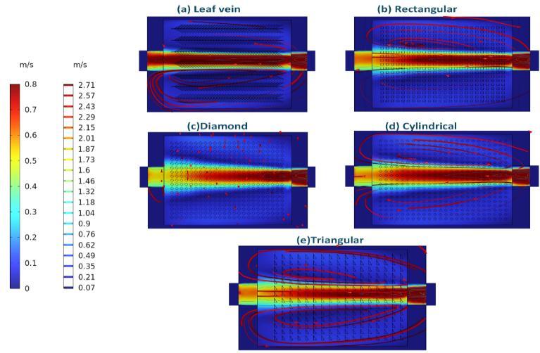
Fig- 11:Velocityfieldandstreamlineribbonsforallfive geometrieswithPG25coolantandC1020substrate
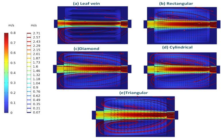
Fig- 12:Velocityfieldandstreamlineribbonsforallfive geometrieswithPG25coolantandaluminumsubstrate
Velocity fields for PG25 coolant visually explain the pressure drop trends. Diamond and triangular pin-fins exhibitsmooth,attachedflow(ΔP<10Pa),whiletheleafvein design shows complex recirculation and jetting (ΔP ~164 Pa). Substrate material has minimal hydraulic impactforPG25,thoughaslightthermalcouplingeffectis notedinthecylindricalfincasewithaluminum.
Fig- 10:ComparisonofpressuredropvaluesofPG25and HFO
For HFO coolant, velocity fields reveal distinct pressuredropmechanisms.WithC1020,theleaf-veindesignshows smootherflow,explainingitslowerΔP(~67Pa).However, diamond and cylindrical pin-fins display severe flow
International Research Journal of Engineering and Technology (IRJET) e-ISSN: 2395-0056
Volume: 13 Issue: 02 | Feb 2026 www.irjet.net p-ISSN: 2395-0072
separation and high-velocity jets, corresponding to their elevated ΔP (~49–51 Pa). The interaction is most severe with aluminum substrates. Diamond and cylindrical fins exhibit chaotic recirculation and intense jetting due to conjugate thermal effects, where the warmer wall lowers local HFO viscosity and increases shear, leading to very high ΔP (>100 Pa). This visually confirms the critical role of material-fluid thermal coupling in hydraulic performance.
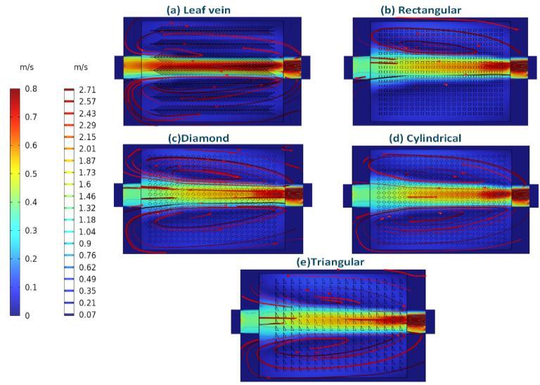
Fig- 13:Velocityfieldandstreamlineribbonsforallfive geometrieswithHFO-1336mzz(Z)coolantandC1020 substrate
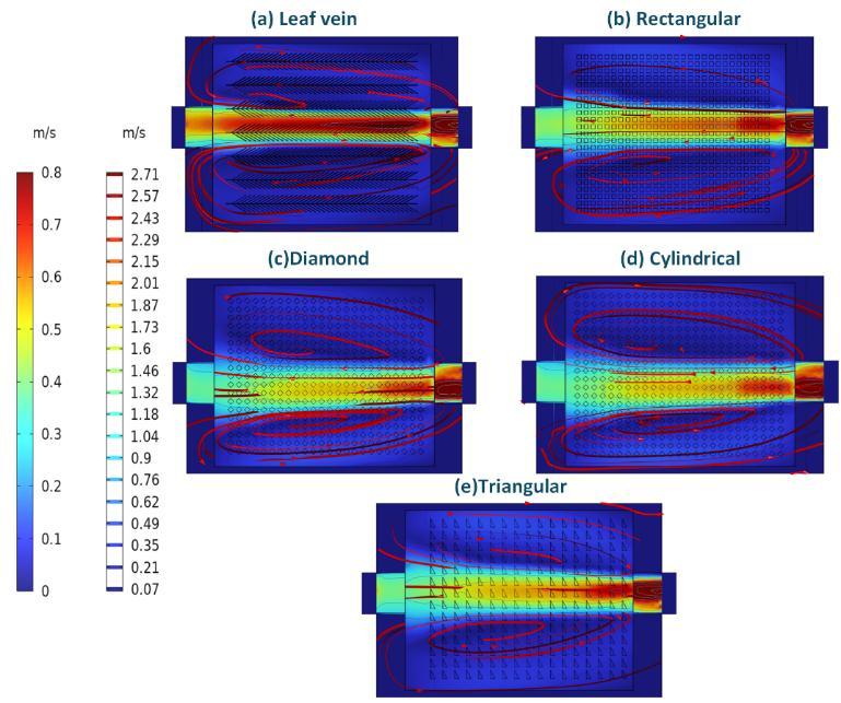
Fig- 14:Velocityfieldandstreamlineribbonsforallfive geometrieswithHFO-1336mzz(Z)coolantandaluminum substrate
3.3. Multi-Objective Performance Ranking
We applied a p-Norm multi-objective analysis (balancing thermal resistance and pressure drop) to seven configurations that satisfied strict energy conservation. Therectangular pin-fin with C1020 and PG25emerged as the most balanced design (p-Norm distance = 0.326),
offering a competitive thermal resistance (0.01910 K/W) and moderate pressure drop (22.8 Pa). Designs with excellent single metrics (e.g., very low ΔP or R_th) were penalized in the combined ranking for poor performance intheothermetric.
Table-3:p-Normbasedmulti-objectiverankingof thermallyandhydraulicallyreliablecoldplate configurations
Theresultshighlightthatinternalgeometryistheprimary driverofperformance,withmaterialandcoolantactingas significant modifiers. Higher-conductivity materials (C1020) did not always yield lower thermal resistance, particularly with HFO, where conjugate effects altered near-wall flow. The optimal design depends on the weighting of thermal versus hydraulic objectives; however, the rectangular pin-fin with C1020/PG25 provides a robust, balanced solution for the imposed conditions.
Basedonthemulti-objectiveranking,the rectangularpinfinconfigurationwithaC1020substrateandPG25coolant wasselectedasthebaselineforparametricoptimization.A full factorial design of experiments was conducted to isolate the effects of fin height (H_f) and pin-fin pitch (S) on thermal-hydraulic performance, with each parameter evaluated at three levels (H_f: 2.50, 2.75, 3.00 mm; S: 2.0, 2.5,3.0mm).
Volume: 13 Issue: 02 | Feb 2026 www.irjet.net
1
3
4
5
6
7
8
9
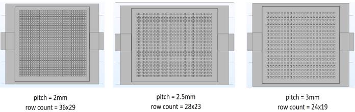
Fig-15:Top-view representation of rectangular pin-fin arrays illustrating the three pitch configurations used in the full factorial parametric study, with a constant effectivefinnedfootprint
4.1. Optimization Results and Analysis
Finheightwasthedominantparametergoverningthermal performance.TheconfigurationwithH_f=3.00mmandS = 2.0 mm achieved the lowest thermal resistance (0.0123 K/W)andthebesttemperatureuniformity.Pressuredrop increased predictably with smaller pitch and greater heightduetoincreasedflowblockage,withvaluesranging from4.9Pato105.7Paacrossthedesignspace.
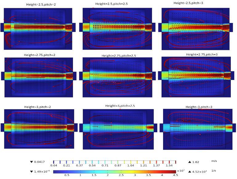
Fig-16:Velocitymagnitudedistributionforallnine rectangularpin-finconfigurationsshowingtheeffectoffin heightandpitchonflowbehavior
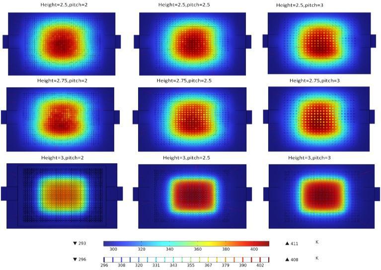
Fig- 17:Temperaturedistributionforallninerectangular pin-finconfigurationsillustratingtheeffectoffinheight andpitchonthermalbehavior
Theresultsestablishacleartrade-off:whilereducingpitch enhances heat transfer, it imposes a significant hydraulic penalty. The optimal balance was confirmed to be the original baseline geometry (H_f = 3.00 mm, S = 3.0 mm), which provides excellent thermal performance (R_th = 0.01910K/W)withamanageablepressuredrop(22.8Pa), validatingitsselectionfromtheinitialcomparativestudy.
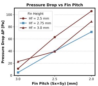
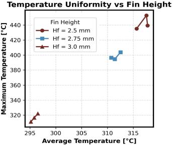
The graphical representation of pressure drop reveals a clear trade-off, where decreasing pitch and increasing height consistently raise flow resistance. Corresponding temperatureplotsconfirmthatthehighestfindensity(2.0 mm pitch) coupled with maximum height (3.00 mm) achieves the lowest thermal resistance and most uniform temperature field, visually validating the quantitative performancetrends.
4.2.
Theparametricstudyconfirmsthattherectangularpin-fin with C1020/PG25 is not only the most balanced design among fundamentally different architectures but is also robust near its original geometric parameters. No alternative combination of height and pitch within the studied range yielded a superior compromise, solidifying it as the recommended configuration for practical high heat-fluxapplications.
International Research Journal of Engineering and Technology (IRJET) e-ISSN: 2395-0056
Volume: 13 Issue: 02 | Feb 2026 www.irjet.net p-ISSN: 2395-0072
Thisnumericalinvestigationsystematicallyevaluatedthe thermal-hydraulic performance of five internal fin architectures under consistent operating constraints. The results demonstrate that geometry is the primary performance driver, with material and coolant selection actingascriticalsecondarymodifiers.Throughavalidated conjugate heat transfer model and a subsequent p-Norm multi-objective analysis, the rectangular pin-fin configuration with a C1020 substrate and PG25 coolant was identified as the most balanced design, offering an optimalcompromisebetweeneffectiveheatremoval(R_th =0.01910K/W)andacceptableflowresistance(ΔP=22.8 Pa). These findings provide a foundational guideline for the design of efficient, practical liquid-cooled cold plates forhighheat-fluxthermalmanagementapplications.
[1] B. R. R. Bapu, S. Kayalvizhi,and S. Murugavalli, “Two phase cooling with nano-fluid for highly dense electronic systems-on-chip – A pilot study,” Microelectron. Reliab., vol. 108, p. 113640, May 2020, doi: 10.1016/j.microrel.2020.113640.
[2] S. Zhu, Z. Zhang, H. Chen, and Y. Li, “Numerical Investigation of a Bionic Vapor Chamber Based on Leaf Veins for Cooling Electronic Devices,” Sustainability, vol. 15,no.2,2023,doi:10.3390/su15021125.
[3] J. Xu, K. Zhang, J. Duan, J. Lei, and J. Wu, “Systematic Comparison on Convective Heat Transfer Characteristics of Several Pin Fins for Turbine Cooling,” Crystals,vol.11,no.8,2021,doi:10.3390/cryst11080977.
[4] M. H. Ruhaidi and N. Darlis, “Analysis of Pin Fin Shapes on Thermal Performances in Microchannel Heat Sink using Computational Fluid Dynamics (CFD),” Prog. Eng.Appl.Technol.,vol.6,no.1,pp.742–751,Apr.2025.
[5] B. M. Diaconu, M. Cruceru, and L. Anghelescu, “Phase Change Materials Applications and Systems Designs:ALiteratureReview,”Designs,vol.6,no.6,2022, doi:10.3390/designs6060117.
[6] B.Zalba, J.M. Marn, L.F. Cabeza, and H. Mehling, “Review on thermal energy storage with phase change: materials, heat transfer analysis and applications,” Appl. Therm. Eng., vol. 23, no. 3, pp. 251–283, 2003, doi: https://doi.org/10.1016/S1359-4311(02)00192-8.
[7] Y.Li,X.Yang,X.Tian,andT.Yu,“Capillary-Driven BoilingHeatTransferonSuperwettingMicrogrooves,”ACS Omega,Sep.2022,doi:10.1021/acsomega.2c05381.
[8] M. Yao, M. Zebarjadi, and C. P. Opeil, “Experimental determination of phonon thermal
conductivity and Lorenz ratio of single crystal metals: Al, Cu,andZn,” J.Appl.Phys.,vol.122,no.13,p.135111,Oct. 2017,doi:10.1063/1.4997034.
[9] A. Zhang and Y. Li, “Thermal Conductivity of Aluminum Alloys A Review,” Materials, vol. 16, p. 2972, Apr.2023,doi:10.3390/ma16082972.
[10] J. Valois, G. Nellis, and J. Pfotenhauer, “Characterization of the thermal properties of OFHC copper at cryogenic temperature,” IOP Conf. Ser. Mater. Sci. Eng., vol. 1301, p. 012167, May 2024, doi: 10.1088/1757-899X/1301/1/012167.
[11] A. R. Dhumal, A. P. Kulkarni, and N. H. Ambhore, “A comprehensive review on thermal management of electronic devices,” J. Eng. Appl. Sci., vol. 70, no. 1, p. 140, Nov.2023,doi:10.1186/s44147-023-00309-2.
[12] J.Pandit,M.Thompson,S.Ekkad,andS.Huxtable, “Effect of pin fin to channel height ratio and pin fin geometry on heat transfer performance for flow in rectangularchannels,”Int.J.HeatMassTransf.,vol.77,pp. 359–368, Oct. 2014, doi: 10.1016/j.ijheatmasstransfer.2014.05.030.
[13] F. Alnaimat and M. Ziauddin, “Experimental investigation of heat transfer in pin-fins heat sinks for cooling applications,” Heat Mass Transf., vol. 57, Aug. 2020,doi:10.1007/s00231-020-02947-1.
[14] M.Alteneiji, A.Raafat,and S.K.Alnuaimi,“Impact ofheightandsecondaryflowpatternsofcircle,squareand triangle shaped pin fins on microchannel heat sinks performance,” Therm. Sci. Eng. Prog., vol. 67, p. 104166, 2025,doi:https://doi.org/10.1016/j.tsep.2025.104166.
[15] K. Madi, A. Raafat, and S. A. Nuaimi, “Enhanced thermal management in microelectronic cooling: A study on pairing multiple pin-fin shapes in microchannel heat sinks,” Int. J. Thermofluids, vol. 28, p. 101283, 2025, doi: https://doi.org/10.1016/j.ijft.2025.101283.
[16] Arjun Kozhikkatil Sunil and Kumar Rakesh, “Optimization of micro pin-fin heat sink with staggered arrangement,”vol.22,no.6,pp.2919–2931,2018.
[17] R. Niranjan, O. Singh, and J. Ramkumar, “ThermoHydraulic Performance of Square Micro Pin Fins under Forced Convection,” Int. J. Heat Technol.,vol. 39, pp. 170–178,Feb.2021,doi:10.18280/ijht.390118.
[18] Numerical investigation of pin-fin thermal performance for staggered and inline arrays at low Reynoldsnumber
[19] N.H.Naqiuddin,L.H.Saw,M.C.Yew,F.Yusof,T.C. Ng,and M. K. Yew, “Overviewof micro-channel design for high heat flux application,” Renew. Sustain. Energy Rev.,
2026, IRJET | Impact Factor value: 8.315 | ISO 9001:2008 Certified Journal | Page9
International Research Journal of Engineering and Technology (IRJET) e-ISSN: 2395-0056
Volume: 13 Issue: 02 | Feb 2026 www.irjet.net p-ISSN: 2395-0072
vol. 82, pp. 901–914, 2018, doi: https://doi.org/10.1016/j.rser.2017.09.110.
[20] M. Hekmatara and M. Kharati-Koopaee, “Numerical study of the influence of pin fin arrangement and volume fraction on the heat transfer and fluid flow phenomena within open microchannels,” Int. Commun. Heat Mass Transf., vol. 155, p. 107595, 2024, doi: https://doi.org/10.1016/j.icheatmasstransfer.2024.10759 5.
[21] A. Abdoli, G. Jimenez, and G. S. Dulikravich, “Thermo-fluid analysis of micro pin-fin array cooling configurations for high heat fluxes with a hot spot,” Int. J. Therm. Sci., vol. 90, pp. 290–297, 2015, doi: https://doi.org/10.1016/j.ijthermalsci.2014.12.021.
[22] H. M. Jaffal, H. S. Jebur, and A. A. Hussein, “Numerical and Experimental Investigations on the Performance Characteristics for Different Shapes Pin Fin Heat Sink,” 2018. [Online]. Available: https://api.semanticscholar.org/CorpusID:211018765
[23] Y. Alihosseini, M. Z. Targhi, M. M. Heyhat, and N. Ghorbani,“Effectofamicroheatsinkgeometricdesignon thermo-hydraulic performance: A review,” Appl. Therm. Eng., vol. 170, p. 114974, 2020, doi: https://doi.org/10.1016/j.applthermaleng.2020.114974.
[24] H.Sallar,M.Irfan,M.M.Khan,andM.W.Shahzad, “Hydro-thermal performance of an I-shaped pin fin microchannel heat sink with variable pin fin height, thickness and orientation,” Int. Commun. Heat Mass Transf., vol. 160, p. 108256, 2025, doi: https://doi.org/10.1016/j.icheatmasstransfer.2024.10825 6.
[25] W. Qu and I. Mudawar, “Experimental and numerical study of pressure drop and heat transfer in a single-phase micro-channel heat sink,” Int. J. Heat Mass Transf., vol. 45, no. 12, pp. 2549–2565, 2002, doi: https://doi.org/10.1016/S0017-9310(01)00337-4.
[26] A.G.FedorovandR.Viskanta,“Three-dimensional conjugate heat transfer in the microchannel heat sink for electronicpackaging,”Int.J.HeatMassTransf.,vol.43,no. 3, pp. 399–415, 2000, doi: https://doi.org/10.1016/S0017-9310(99)00151-9.
[27] H. Wang, Z. Chen, and J. Gao, “Influence of geometric parameters on flow and heat transfer performance of micro-channel heat sinks,” Appl. Therm. Eng., vol. 107, pp. 870–879, 2016, doi: https://doi.org/10.1016/j.applthermaleng.2016.07.039.
[28] X. F. Peng and G. P. Peterson, “Convective heat transfer and flow friction for water flow in microchannel structures,” Int. J. Heat Mass Transf., vol. 39, no. 12, pp.
2599–2608, 1996, doi: https://doi.org/10.1016/00179310(95)00327-4.
[29] L. Yue, C. Qi, and M. Tang, “A novel composite bionic leaf vein and honeycomb microchannel heat sink applied for thermal management of electronic components,”Appl.Therm.Eng.,vol.252,p.123716,2024, doi: https://doi.org/10.1016/j.applthermaleng.2024.123716.
[30] H. Xia, J. Wang, Y. Shen, and K. Fang, “A liquidcooled plate based on bionic flow channels evolved from the shape of leaf veins and tree roots,” Int. J. Therm. Sci., vol. 208, p. 109468, 2025, doi: https://doi.org/10.1016/j.ijthermalsci.2024.109468.
[31] X. Wang, Z. Zhou, H. Li, G. Xie, L. Meng, and Z. Zhang, “Programmed constructions of novel bionic heat sinks inspired by leaf venation pattern,” Int. J. Heat Mass Transf., vol. 251, p. 127353, 2025, doi: https://doi.org/10.1016/j.ijheatmasstransfer.2025.12735 3.
[32] Sun Guangqiang, Li Zhiqiang, Wang Fang, Liu Xianfei, and Ba Yichun, “Study on cooling of bionic leafvein channel liquid-cooled plate for lithium-ion battery pack,”vol.28,no.5,pp.3907–3919,2024.
[33] K.Wang,Y.Shi, J.Chen,and Y.Dai,“ABiomimetic Microchannel Heat Sink for Enhanced Thermal Performance in Chip Cooling,” Biomimetics, vol. 10, no. 7, 2025,doi:10.3390/biomimetics10070459.
[34] J.Wang,X.Liu,F.Liu,Y.Liu,F.Wang,andN.Yang, “Numericaloptimizationof thecooling effectofthebionic spider-web channel cold plate on a pouch lithium-ion battery,”Case Stud.Therm. Eng.,vol.26,p. 101124, 2021, doi:https://doi.org/10.1016/j.csite.2021.101124.
[35] X. Yang et al., “Model–based and data–driven approaches for PEMFC bionic spider web channel cold plate structure design and liquid cooling performance optimization study,” Renew. Energy, vol. 256, p. 123957, 2026,doi:https://doi.org/10.1016/j.renene.2025.123957.
[36] E. Foronda, F. J. Ramírez-Gil, Á. Delgado-Mejía, L. M. Ballesteros, J. S. Rudas, and L. C. Olmos-Villalba, “Thermal enhancement of heat sinks with bio-inspired textured surfaces,” Therm. Sci. Eng. Prog., vol. 46, p. 102170, 2023, doi: https://doi.org/10.1016/j.tsep.2023.102170.
[37] M. Bobič, B. Gjerek, I. Golobič, and I. Bajsić, “Dynamicbehaviourofaplateheatexchanger:Influenceof temperature disturbances and flow configurations,” Int. J. Heat Mass Transf., vol. 163, p. 120439, 2020, doi: https://doi.org/10.1016/j.ijheatmasstransfer.2020.12043 9.
© 2026, IRJET | Impact Factor value: 8.315 | ISO 9001:2008 Certified Journal | Page10
International Research Journal of Engineering and Technology (IRJET) e-ISSN: 2395-0056
Volume: 13 Issue: 02 | Feb 2026 www.irjet.net p-ISSN: 2395-0072
[38] A. Alenezi, H. M. Ali, and P. E. Phelan, “Experimental investigation of the effect of ultrasonic waves on heat transfer enhancement and pressure drop for propylene glycol/water mixtures in a rectangular minichannel heat sink,” Appl. Therm. Eng., vol. 267, p. 125717,2025,doi: https://doi.org/10.1016/j.applthermaleng.2025.125717.
© 2026, IRJET | Impact Factor value: 8.315 | ISO 9001:2008 Certified Journal | Page11