
International Research Journal of Engineering and Technology (IRJET) e-ISSN: 2395-0056
Volume: 12 Issue: 10 | Oct 2025 www.irjet.net p-ISSN: 2395-0072
International Research Journal of Engineering and Technology (IRJET) e-ISSN: 2395-0056
Volume: 12 Issue: 10 | Oct 2025 www.irjet.net p-ISSN: 2395-0072
Nor Hidayah Daud1, Alyani Ismail1, Aduwati Sali1, Mohd Hafizal Ismail2
1Wireless and Photonics Networks Research Centre, Department of Computer and Communication Systems Engineering, Faculty of Engineering, Universiti Putra Malaysia, 43400, UPM Serdang, Selangor Darul Ehsan, Malaysia
2Department of Nature Parks and Recreation, Faculty of Forestry and Environment, Universiti Putra Malaysia, 43400, UPM Serdang, Selangor Darul Ehsan, Malaysia ***
Abstract - The size restrictions present a significant issue when designing antennas for Internet of Things (IoT) applications. To address this issue, this research investigates and develops a suggested antenna that consists of 1 × 2 Rectangular Microstrip Patch Arrays Antenna integrated with a fishbone-shaped slot and rounded corner based on a truncated ground plane and a T-shaped slot structure. From the results obtained, the antenna shows a better performance, including a return loss magnitude of -18.0 dB. The overall dimensions of the proposed antenna are 123.0 × 66.0 mm2 with a gain of 2.30 dBi. Thus, the final outcomes indicate that, the use of this antenna is anticipated to yield numerous benefits and feasible to communicate for IoT applications.
Key Words: Antenna Arrays, EM wave propagation, IoT Applications, Rectangular Patch Antenna, and Sub-GHz Frequency.
IoT connects, communicates, and exchanges data among devices over the internet, revolutionizing technology. Owing to its many applications, IoT is pursued as a key technology for improving economic growth and quality of human life. As IoT grows, researchers are developing novel antenna designs, materials, and technologies to boostperformanceandefficiency[1]
Designing antennas for IoT applications presents unique challenges due to the diverse requirements of each application field such as agriculture, medical, security, smart home, tracking devices associated with wireless technology going towards future [2, 3] Major issues include miniaturizing IoT devices, which requires tiny antennaswithsufficientsignalstrengthandrange
Current antenna technology has challenges with frequency,bandwidth(BW),size,weight,materialchoices, and energy efficiency, requiring new solutions [1] To mitigate these challenges, various antenna designs have been investigated and many reduction strategies have been put forth byacademicsworldwide toshrink thesize oftheantennas.
Modification in theshapeof patchantennashashelped to achievedesirableantennaperformance.Inaddition,patch antennas support various feed techniques and can be developedintoarraystoimprovethegainandachievethe desired pattern requirements. Owing to these reasons, patch antennas have proven to be a strong candidate for IoTapplications.Thus,thisresearchtacklestominiaturize the antenna while maintaining the antenna performance. Theperformancesoftheproposeantenna wereevaluated in terms of dimensions, gain and return of loss, S11 (dB) To achieve this, the 1 × 2 rectangular microstrip patch arrays antenna have been preferred for antenna design since its characteristics are suitable for commercial wirelessapplications. Besides,the microstrippatcharray antennaareeasytofabricateduetothesimpledesign.
Recently,thepreviousresearcheshavebeendevelopedon miniaturization antenna for wireless applications. Currently,themostcommonapproachforminiaturization antenna involve the use of specialized structures like metamaterials or fishbone slots, and optimizing designs for specific frequencies to improve the antenna performance. A thick dielectric substrate with a high relative permittivity ɛr is a common technique to miniaturize microstrip patch antenna (MPA). However, miniaturization techniques in antenna design often leads to increased surface wave excitation within the substrate, which can negatively impact BW and radiation efficiency [4]
Changingtheshapeofthepatchorintroducingslotsonthe patch is a commonly used technique to miniaturize the MPA [5]. The microstrip patch's resonance frequency will be lowered by the addition of the slots, which will aid in increasing the current route within the patch area and resulting in a reduction in size [6]. Besides, numerous ground plane modifications can be made to miniaturize theMPA.
However most of the studies have not been clearly stated thewayofintegratingtheminiaturizationtechniquewhile maintainingtheantennaperformance.Besides,theeffectof different channel characterization parameters such as conductivity, frequency and transmitter and receiver
International Research Journal of Engineering and Technology (IRJET) e-ISSN: 2395-0056
Volume: 12 Issue: 10 | Oct 2025 www.irjet.net p-ISSN: 2395-0072
antenna separation is not deeply discussed. Thus, the suggested designed of an antenna resulting in poor feasibility of antenna on the development performance practices.
A research methodology for antenna design involves a systematic approach encompassing design, simulation, fabrication, and testing. The design of an antenna begins with a thorough understanding of the application's requirements, specifically the desired communication range, frequency, followed by selecting appropriate antenna types and materials and other performance characteristics.
Simulation tools are used to model and optimize the design, and prototypes are fabricated for experimental validation. Finally, the antenna's performance is evaluated through measurements and compared with simulation results. This process often iterates, with simulations guidingdesignadjustmentstomeetperformancegoals.
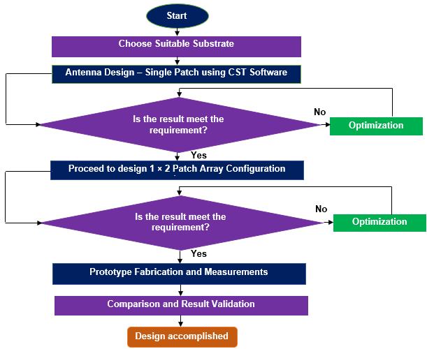
The microstrip patch antennas were the type of antenna element taken into consideration in this study, both as individual elements and in arrays. The proposed sets of design equations, have been used to determine the dimensions of the conventional microstrip patch antenna. At a resonance frequency of 921 MHz, the antenna is
created and modelled using Computer Simulation Technology(CST)MicrowaveStudio.
All the predefined parameters in Table 1 were calculated based on the theoretical formulas. The design was built on a substrate of FR4 epoxy substrate with a dielectric constant, ɛr = 4.3, a thickness, h = 1.60 mm, a metallizationthicknessof t =0.035mm,whereasthespeed oflight, c =3×10⁸ m/s.
Thetentativelength, Lp andwidth, Wp ofthepatchwere calculated as 78.35 mm and 100.05 mm, respectively, for an operating frequency of 921 MHz. After completing the calculation of basic patch antenna dimensions, then, the design antenna have been optimized until the operating frequencyisresonantat921MHzasshowninFigure2.
Table-1: PredefinedParameterforMicrostripPatch
Theminimumvalueofthesimulatedonreturnloss,S11 (dB)is-22.67dB.Meanwhile,thesimulatedBWofasingle patch element antenna is 20 MHz with a fractional bandwidth of 2.17%, which is not wide enough for IoT applications. Besides, the dimensions of the single patch elementweredrasticallyoptimizedto75.5mm×90.6mm (Lp × Wp).
Basedonthesimulatedresults,thesinglepatchelement antenna does not fulfil the design specifications for proposed antenna in terms of dimensions, BW and return loss, S11 (dB) of the antenna. Therefore, it is proven that some modifications to the single patch element antenna
International Research Journal of Engineering and Technology (IRJET) e-ISSN: 2395-0056
Volume: 12 Issue: 10 | Oct 2025 www.irjet.net p-ISSN: 2395-0072
should be made in order to achieve the best results in antennaperformance.
Thus, anantenna array wascreated byconnecting two single patches together via the combined corporate feed network. This is dueto the fact thatemploying the idea of array design is one of the most popular ways to increase thegainofmicrostrippatchantennas.
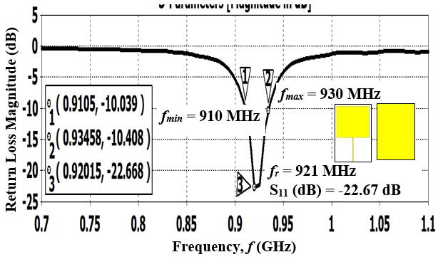
-2:Simulatedresultsofreturnloss,S11 (dB)
3.2 Design Evolution Process of Antenna Arrays
Anarrayantennathatconsistsoftwoor moreidentical patches refers to a configuration where multiple antenna elements, typically of the same size and shape, are placed nearformacollectiveantennasystem[7,8].Thedesignof proposed antennas has evolved from basic rectangular patches to more complex structures like slotted patches, rounded corners and truncated ground plane to achieve thedesiredcharacteristics.
Initially, the structure of Ant 1 was formed by using a simple of rectangular patch antenna as shown in Figure 3 (a). An additional fishbone – shaped slot was added into the design to form Ant 2. It was depicted in Figure 3 (b). Then, a rounded corner structure was added to Ant 2, as showninFigure3(c)andthisstructureformedthe Ant 3 Meanwhile, in Figure 3 (d), Ant 4 was formed by adding theT-shapedslotstructureattheback planeofsubstrate. The final consideration of the proposed antenna is typicallybasedontheevaluationofitsperformanceacross various parameters such as dimensions, return loss, gain, radiationpatternsandBW.
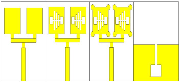
-3:Proposedgeometryofvariousantennas involvedinthedesignevolution
In this study, there are four steps have been taken to complete the intended antenna. In order to discover the optimal optimization during the simulations, four modified antennas were suggested. Only one of the four types of designs will be used to carry out this investigation. The final design's chosen dimensions are determined bythedeeperresonancedipsofS11 (dB), tiny dimensions,improvedgain,andreturnlossmagnitude(in termsofdB).
During the proposed antenna are being designed, it is important to know which parameters have the greatest influence on the characteristics and performance of the designed antenna as a measure of how well matched an antennais.Indesigningtheantenna,considerationisgiven to the basic characteristicsof the proposedarrayantenna, including its dimension, BW, resonance frequency, and reflectioncoefficient.
BasedontheFigure4,itcanbeseenthatagoodreturn loss has been obtained from the simulated result. Simulation of conventional patch array antenna display that the S11 (dB) parameterandBW reaches tothevalue36.6dBand290MHzrespectively.Thisantennaresonates from 810 MHz to 1100 MHz at 904 MHz operating frequency.Thus,theFBWis32.1%.
International Research Journal of Engineering and Technology (IRJET) e-ISSN: 2395-0056
Volume: 12 Issue: 10 | Oct 2025 www.irjet.net p-ISSN: 2395-0072
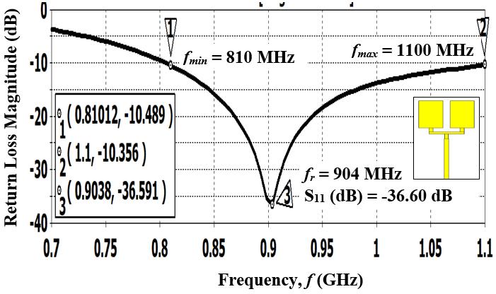
-4:SimulatedS11 (dB)andBWof Ant 1
The second step presents the design of a conventional antenna, Ant 1 incorporated with fishbone-shaped slot structurewhichiscalledas Ant 2.The Ant 2 wasproposed to enhance the gain and the impedance matching of the structure. As compare to the previous result, it is proved that, by adding fishbone-shaped slot structure into this design,themagnitudeofitsreturnlossisS11 (dB)equalto38.9dB Moreover,thehighBWwasachievedat286MHz. Thisantennaresonatesfrom801MHzto1087MHzat893 MHzoperatingfrequency.TheFBWis32.0%.
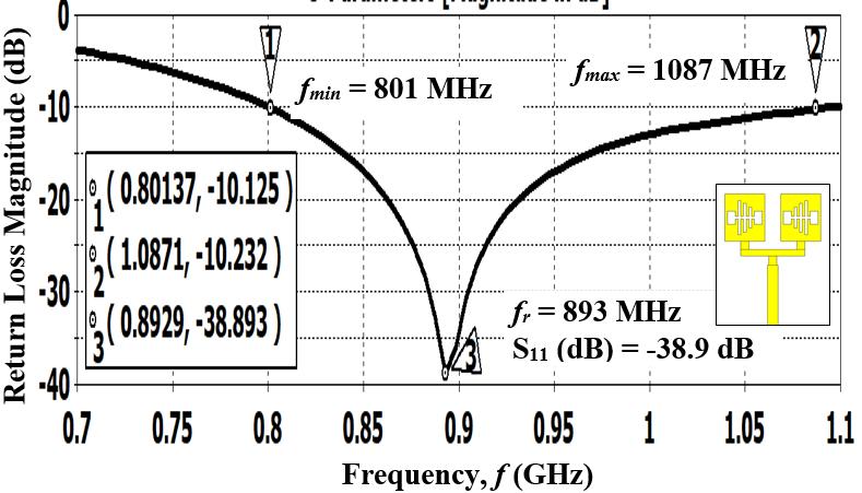
-5:SimulatedS11 (dB)andBWof Ant 2
Here, in this designed, the rounded corner structure were added in this design to form an Ant 3. The effect on the return loss magnitude, S11 (dB) was explored in Ant 3 An interesting feature of this kind of antenna is that, the antenna shifted to the lower frequency and improve the magnitude of its return loss is S11 (dB) when the rounded corner structure were added into this designed. This structureresonatesat877MHzwith-39.1dB.
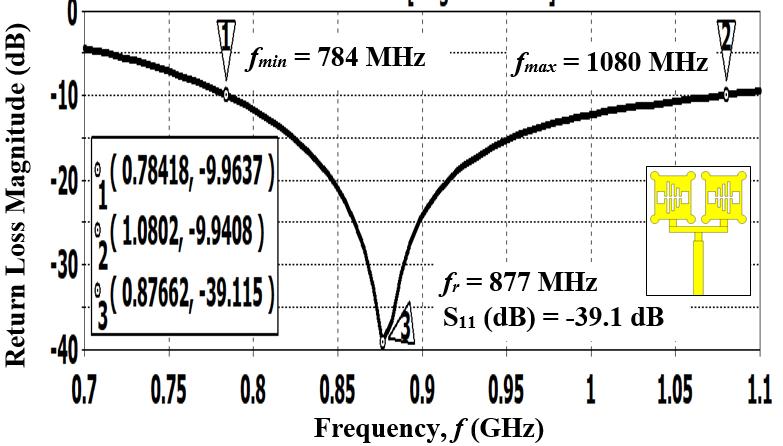
-6:SimulatedS11 (dB)andBWof Ant 3
Forthefinalstages,anantennawasaddedtheT-shaped slot structure at the back plane of substrate in order to further improve the antenna’s performance. It was called as Ant 4. In order to control the impedance BW of a Tshapedslotstructure,themodifiedtruncatedgroundplane functions as an impedance matching element. This is becausetheinductivenatureofthepatchisneutralizedby thetruncation,whichproducesacapacitiveloadthatyields an almost pure resistive input impedance. The simulation of antenna BW is 33.2% (800 MHz to 1100 MHz) with a resonant frequency of 904 MHz and the return loss of42.0dB.
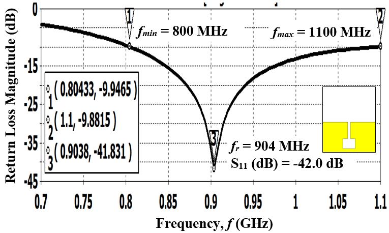
From the simulated results obtained in Figure 7, it is observedthat,thestructuralconfigurationoftheproposed rectangularpatcharrayantennawithfishbone-shapedslot and rounded corner structure was chosen to go further in thisresearch.Thisantennawasdenotedas Ant 4.The Ant 4 yield the best of performance as compared to Ant 1, Ant 2 and Ant 3 respectively. Besides, Ant 4 was chosen since it close to 921 MHz with high return loss of -42.0 dB and a BWof300MHz.
International Research Journal of Engineering and Technology (IRJET) e-ISSN: 2395-0056
Volume: 12 Issue: 10 | Oct 2025 www.irjet.net p-ISSN: 2395-0072
This result offered good starting point to discover furtherontherightconditiontominiaturizethedimension of antenna as well as increasing the gain and BW of the design.Allthesimulationsrelatedtotheresultsreportedin Table 2 were performed considering the antenna in freespace.
Table -2: ComparisonofParametersonDifferentTypesof AntennaStructure
Ant 3
After the parametric studies in the simulation process were finished successfully, the optimal shape of the proposed IoT antenna was found based on the expected frequency band. The schematic design of the proposed antenna is demonstrated in Figure 8, including its optimised dimensions. The overall dimensions of the proposedantennaare123.0×66.0mm2
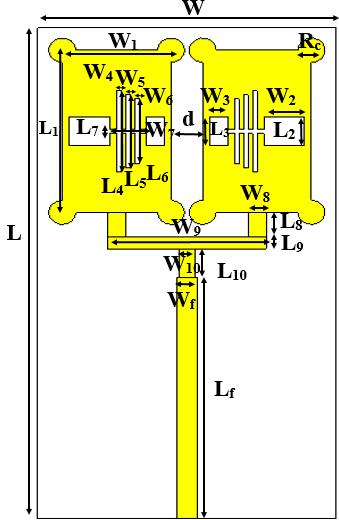
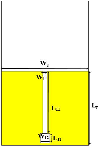
Figure -8:Schematicviewoftheproposed1×2 rectangularpatcharrayantenna
Table -3: Dimensionsoftheproposedantenna
4.3 Simulated Return Loss, S11 (dB)
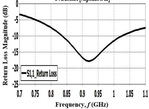
Return loss is an important parameter when testing antennas,asitdirectlyrelatestoimpedancematchingand the maximum power transfer principle. A higher (more negative) return loss, S11 (dB) is an acceptable level to describethelossofthepowerwhichreflectsbackfromthe antennawithoutbeingradiated.Theresultofthesimulated return loss, S11 (dB) with respect to the centre frequency fortheproposedantennaisdisplayedinFigure9.
4.4 Simulated Voltage Standing Wave Ratio (VSWR)
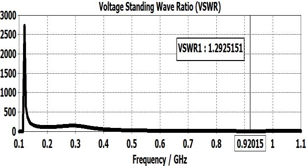
By theoretical, an ideal VSWR of 1.0 would mean that the impedance of the antenna is perfectly matched to the transmissionline,resultinginnoreflectedpower.Basedon the result obtained from the CST simulation, the VSWR = 1.3 at operating frequency of 921 MHz. This represents a goodimpedancematchandefficientpowertransfer.Figure
International Research Journal of Engineering and Technology (IRJET) e-ISSN: 2395-0056
Volume: 12 Issue: 10 | Oct 2025 www.irjet.net p-ISSN: 2395-0072
10 depicted the result form the simulated VSWR versus frequency.
-10:SimulatedVSWRversusfrequency
4.5 Simulated Gain
From the simulated results, the gain of the proposed antenna operatingin921MHzexhibitsthemaximumgain of2.30dBiasshowninFigure11
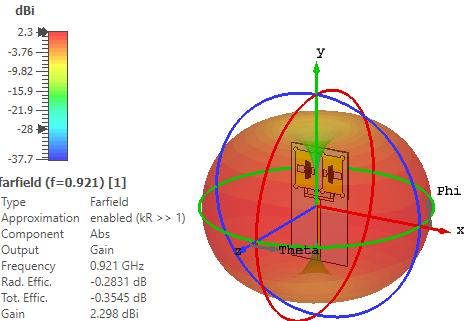
Figure -11:Simulatedgainoftheproposedantennaat 921MHz.
4.6 Simulated Radiation Pattern
The results of the simulated radiation patterns of the proposed antenna on the cutting planes φ = 0° (E-plane) andφ=90°(H-plane)arepresentedandbrieflydiscussed. ThenatureofH-planeradiationpatternsisomnidirectional while the E-plane radiation patterns are bidirectional (dumb-bell shaped). Figures 12 (a) and (b) illustrate the simulatedradiationpatternsinthey-zandx-zplanesatthe centerfrequencyof921MHzrespectively.
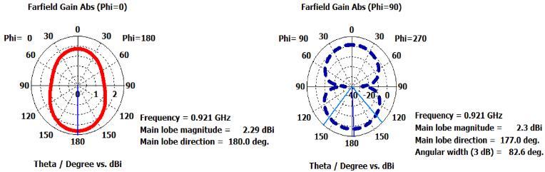
Figure-12:Simulatedradiationpatternoftheproposed antenna(a)E-plane(b)H-planeradiationpattern
4.7 Comparison of the Proposed Antenna and Previously Reported Designed
The performance of these antennas is succinctly summarizedinTable4.Thetableincludesessentialdetails suchasfrequencybands,returnloss,S11 (dB),physicalsize andgain(dBi).Thiscompilationservesasacomprehensive overview of various patch antennas, offering a quick reference for comparing their characteristics and specificationsinthecontextofperformanceanalysis.
Table -4: Performancecomparisonbetweentheproposed antennawiththeexistingreportedantennas
& Raju, 2021 [9]
Dala et al., 2021 [10] 868
Muntoni et al., 2021 [11] 867
Casula et al., 2023 [12] 867 915
This study presents a proposed designed of 1 × 2 rectangular microstrip patch array antenna integrated with fishbone-shaped slot and rounded corner based on truncated ground plane and T-shaped slot structure is designed and presented for wireless communications. Initially, the antenna is constructed with a single patch. It
International Research Journal of Engineering and Technology (IRJET) e-ISSN: 2395-0056
Volume: 12 Issue: 10 | Oct 2025 www.irjet.net p-ISSN: 2395-0072
was then converted into a 1 × 2 patch array after the results of antenna properties such operating frequency, radiation patterns, return loss, S11 (dB), antenna dimensions, and antenna gain were assessed. The total area of the proposed antenna was minimized by 8112 mm2 (around 70.15%), especially in comparison to the previouslyreporteddesignsof27200mm2
The suggested antenna is designed to satisfy sub-GHz frequency requirements in 921 MHz operating mode. Compared with other microstrip antennas at the same profile,theproposedantennaachievesahighergainat2.3 dBiwiththesimulatedreturnloss,S11 (dB)of-18.0dBand adimensionsof,123.0mm×66.0mm.Thisisalsoproven that, with a suitable selection of antenna substrate integratedwithseveralminiaturizationmethodsaswellas suitable operating frequency will reflected the antenna performances.
[1] S. Khan, T. Mazhar, T. Shahzad, A. Bibi, W. Ahmad, M. A. Khan,... and H. Hamam, “Antenna systems for IoT applications: a review,” Discover Sustainability, vol 5, Nov2024,pp 1-27,https://doi.org/10.1007/s43621024-00638-z.
[2] D. G. Arnaoutoglou, T. M. Empliouk, T. N. Kaifas, M. T. Chryssomallis, and G. Kyriacou, “A review of multifunctional antenna designs for internet of things,” Electronics, vol 13, Aug 2024, pp 1-33. https://doi.org/10.3390/electronics13163200.
[3] M. S. Rana, O. Islam, S. A. Shikha and M. Faisal, "IoT Application using a Rectangular 2.4 GHz Microstrip Patch Antenna," International Conference for Advancement in Technology (ICONAT), Goa, India, Apr 2023, pp. 1-4, doi: 10.1109/ICONAT57137.2023.10080448.
[4] V.Awasthi,P.Singh,S.Gupta,S.Kushwaha,S.Sethand S. Jain, “Miniaturization techniques for next generation patch antennas: A review,” International Journal of Science Management & Engineering Research (IJSMER), structure,March2023.vol. 8,pp.1124-1132.
[5] M. Boudjerda,A.Reddaf,A. Kacha, K.Hamdi-Cherif, T. E. Alharbi, M. S. Alzaidi,... and S. S. Ghoneim, “Design and optimization of miniaturized microstrip patch antennasusinga geneticalgorithm,”2022 Electronics, vol. 11,pp.1-14
[6] M. U., Khan, M. S. Sharawi and R. Mittra, “Microstrip patch antenna miniaturisation techniques: a review,” 2015IETMicrowaves,Antennas&Propagation,vol.9, pp.913-922.
[7] A.VinodiaandK.Cecil“DesignofNovelArrayFlexible Antenna with Enhancement in The Performance By Using Transparent Material,” International Research Journal of Engineering and Technology (IRJET), vol. 11,April2024,pp.1312–1318.
[8] A. Yadav, and M. N. Ahmad, “ANALYSIS OF ANTENNA ARRAYSFORMILLIMETERWAVECOMMUNICATION,” International Research Journal of Engineering and Technology(IRJET),vol.10, June2023,pp.625-630.
[9] M.V.Krishna&G.S.N.Raju,“Triangleshapedantenna design for IoT-based LoRaWAN applications. SAMRIDDHI: A Journal of Physical Sciences, Engineering and Technology, ”June2021, 13(01),pp.8-11.
[10] A. Dala & T. Arslan, “Design, implementation, and measurement procedure of underwater and water surface antenna for Lora communication,” February 2021, Sensors, vol. 21, pp. 1-17, https://doi.org/10.3390/s21041337
[11] G. Muntoni, G. A. Casula, G. Montisci, T. Pisanu, H. Rogier & A. Michel, “An eighth-mode SIW antenna for low-power wide-area network applications,” April 2021 Journal of Electromagnetic Waves and Applications, 35(13), pp. 1815-1829, https://doi.org/10.1080/09205071.2021.1918264
[12] G. A. Casula, G. Montisci and G. Muntoni, "A Novel Design for Dual-Band Wearable Textile Eighth-Mode SIW Antennas," in IEEE Access, vol. 11, pp. 1155511569,2023,doi:10.1109/ACCESS.2023.3242602.