International Research Journal of Engineering and Technology (IRJET) e-ISSN: 2395-0056

Volume: 09 Issue: 09 | Sep 2022 www.irjet.net p-ISSN: 2395-0072

International Research Journal of Engineering and Technology (IRJET) e-ISSN: 2395-0056
Volume: 09 Issue: 09 | Sep 2022 www.irjet.net p-ISSN: 2395-0072
Mr. Shreekrishnadevaraya, Prof. Dr. C. Lakshminarayana,
Dept. of Electrical and electronics engineering BMS College of engineering Bengaluru Professor, Dept. of Electrical and electronics Engineering, BMS College, Karnataka, India ***
Abstract: Power supply system difficulties include supply line disruptions, harmonics in line current, and low power factor. To tackle these challenges, a control system consisting of dc link voltage controller and proportional integral (PI) current controller using phase angle estimator is proposed. Current controllers are designed using PI controllers, and simulations are run with both PI and DQ model-based controllers. Fast reaction and enhanced power quality are shown by reduced AC mains harmonics, improved power factor, and wellregulated DC output voltage. This model can be simply used in the actual system, minimizing design and control complexity. This paper proposes vector control of AC/DC FEC using a single current sensor. V-phase current estimate uses grid side d-q axis current controller reference currents. FEC maintains steady DC-link voltage, which can be changed within limits. It pulls sinusoidal current from the mains and can alter input power factor. MATLAB/Simulink simulations justify the proposed current estimation method.
Key Words: Active Front End drive (AFED), Variable frequency drive (VFD), v/f vector control method, and Inductionmotor(IM),PIControllerandPFimprovement
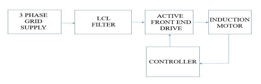
ActivefrontendconverterconvertsACtoDC.Thetwomain benefits of active rectifier systems over passive rectifier systemsareoutputvoltageregulationandreductionofAC input harmonics. Active rectifier is a non-isolated AC-DC converter. Since "rectifier" implies a unidirectional converter,thename"ActiveFront-end"perfectlydescribes thesamething.Insteadof"outputvoltage,"Iprefer"DClink voltage," the DC side of the converter can be either the output or the input, and it is bi-directional. DC power is transferredto AC with the help ofan active front-end or activerectifier. AFEDiscontrolledbysinglecurrentsensor The AFED maintains the DC link voltage and restricts harmonic current. It transfers active power between load and grid. Single-current-sensor FEC uses vector control. Differentmethodsareusedtoconstructcurrentsignalsin single-sensorACmotordrives.
This single-current-sensor FEC is new. Active front end (AFE)hasmanyadvantagesovertheothertechniques.AFEbasedconverterscanreducelinecurrentharmonicscaused by high-frequency switching, generate power, maintain powerfactor,andregulateDC-linkvoltage.Non-sinusoidal input current causes harmonic distortion in conventional converters. PWM converters could help. PWM utilizes sinusoidalpulsewidthmodulation,akindofcarrier-based PWMduringwhichgatingpulsesareproducedbycomparing thesinusoidalmodulatingsignalwiththetriangularcarrier signal. PI-controllers are used. Associated controlled variables decoupling variables using dq transformation improvesvoltageresponseandreducesharmonicdistortion.
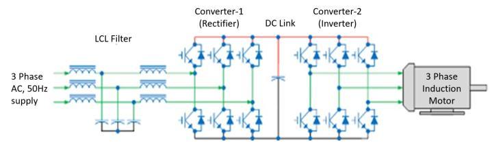
Inanactivefrontend,insulatedgatebipolarresistorsused toconverttheincomingACpowertoDCratherthandiodes in the rectifier (IGBTs). IGBTs are electronic switchingcontrolleddevicesthatiswhytheterm"active"frontendis used(asshowninFigure2).
Totalharmonicdistortion(THD)isreducedto5%orlessby the active front end, which constantly monitors the linecurrent waveform and shapes it to be sinusoidal. The switchingfrequencyoftheIGBTsleadstohigherharmonics
International Research Journal of Engineering and Technology (IRJET) e-ISSN: 2395-0056
Volume: 09 Issue: 09 | Sep 2022 www.irjet.net p-ISSN: 2395-0072
thathavetobeattenuated;THDisonlyevaluatedforlowerorderharmonics.InVFDapplications,harmonicdistortion also makes up the majority of the system's power factor. Twofactorsdeterminethepowerfactor.Theinitialfactoris thephaseangle,alsodefinedasthedisplacement,between the applied voltage and the generating current. For a variablefrequencyactivefrontenddrivetofunction,voltage andcurrentmustremaininphaseandtheircosinedistance mustbekeptclosetounity(1).Totalharmonicdistortionisa secondcomponentthatimpactspowerfactorinaninverse manner; the higher the THD, the lower the power factor. Therefore, a front end with an active design that lowers harmonicdistortion(forinstance,from45to5)significantly improvesthesystem'spowerfactor.
PF=cosθ/√(1+(〖THD)〗^2) (eq.1)
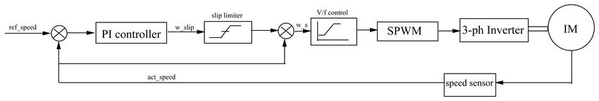
The error signal one which results from this compared is thenfedtothePIcontroller,whichprovidestheangularslip speed,whichisthencomparedtotheactualspeedagainwith theslipregulatortokeepthespeedwithinallowablelevels. Atlast,theerrorsignalisfedtotheV/Fcontrolblock,which isfedtotheSPWM,andandatlasttotheinverter,
Table -1: Specifications of AFED
Specifications
Parameter Values Induction motor parameters
Ratin g
3-phaseAC inputvoltage 415V SquirrelcageIM 5.4HP
Inputsupply frequency 50Hz Powerrating 4kW
DClinkvoltage 800V Voltagerating 400V IGBTswitching frequency 20kHz MotorSpeed 1430 RPM
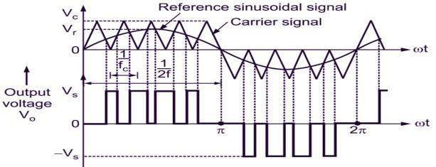
Abasicsourcevoltageinverter'sswitchescanbeswitched onandoffasrequired.Theswitchisactivatedordeactivated once for each cycle. Accordingly, a square waveform is formed (as shown in Figure 3). However, if the switch is periodically turned on, an improved waveform with a harmonic profile is produced. The sinusoidal PWM waveform is created by matching the desired modulated waveformwithatriangularwaveformwithahighfrequency. Depending on whether the voltage of the signal is less or morethanthatofthecarrierwaveform,theoutputvoltageof theDCbuswilleitherbenegativeorpositive.
Whenathree-phaseinductionmotorisbeingcontrolledina closedloop,thespeedsensorisusedtocomparetheactual speedtothereferencespeedfirst(asshowninFigure4)
1.2.2 Design of LCL Filter and Controllers (eq.2) (eq.3) (eq.4) (eq.5) (eq.6) (eq.7) (eq.8) (eq.9) (eq.10) (eq.11)
International Research Journal of Engineering and Technology (IRJET) e-ISSN: 2395-0056
Volume: 09 Issue: 09 | Sep 2022 www.irjet.net p-ISSN: 2395-0072
Table -2: Results obtained from eq.2 to eq.11
Parameter Value L1 0.54mH L2 0.914mH C 60µF
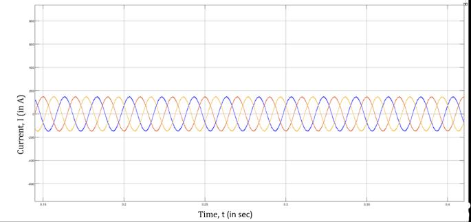
I. Line Current without filter
1.2.3 Design
Controllers Twocontrolloopsexist. 1)Constantoutsidevoltageloop 2)Theinnercurrentloopmusthaveaunitypowerfactor
AsshowninFigure7,Itisobservedthatthereisnoiseinline current which may damage the circuit components in eliminatenoiseweareintroducingLCLfilteratinputside.
II. Line Current with filter
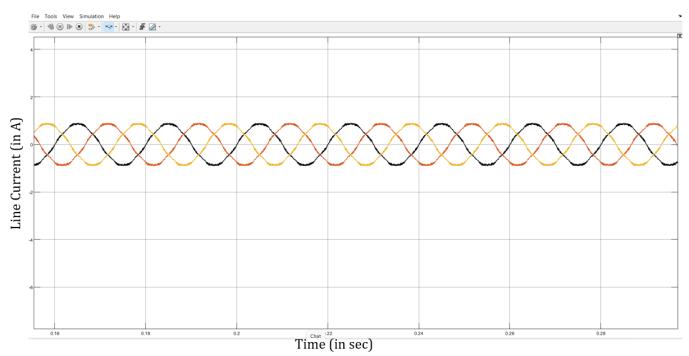
Figure5converter-1controlloop
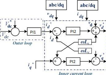
Table -3: PI-Controller Design Parameters
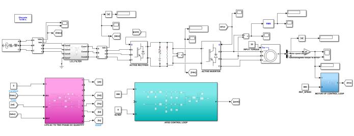
2. Simulink model of Active Front End Drive fed Induction Motor
AsshowninFigure8,itisobservedthatnoiseinlinecurrent hasbeeneliminatedbyusingLCLfilter.Withtheresultwe are able to achieve THD less than 5% as per industrial standardIEEE-519
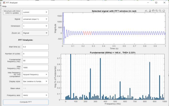
III. Harmonics Analysis
Figure 6 SimulinkModelofAFED
Figure 9 HarmonicSpectrumofLinecurrent
International Research Journal of Engineering and Technology (IRJET) e-ISSN: 2395-0056
AsshowninFigure9,itisobservedthatfundamentalTHDis 2.33% calculated by using FFT analysis using MATLAB software.
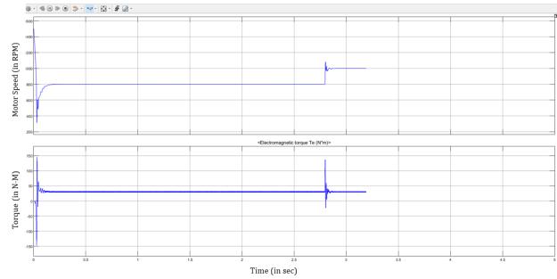
AsshowninFigure12,itisobservedthatspeedcontrolof3phaseinductionmotorisachievedbychangingthereference speed according to the actual speed with the help of v/f controlmethod.
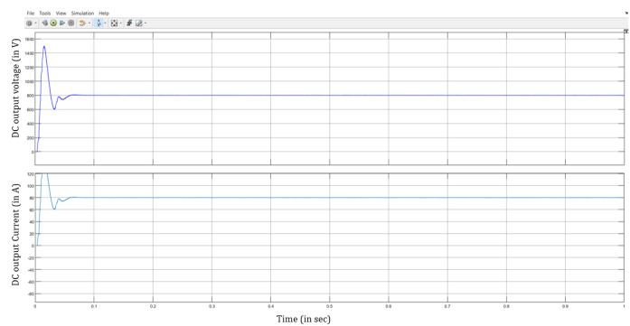
As shown in Figure 10, We are able to achieve fixed DC outputvoltageof800VfromConverter1(ActiveRectifier) whichisinputtotheConverter2(Inverterdrive).
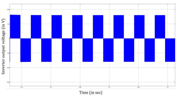
As shown in Figure 11, it is observed that the obtained inverteroutputvoltageisasthatofexpectedoutputvoltage
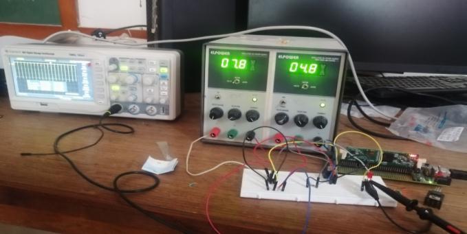
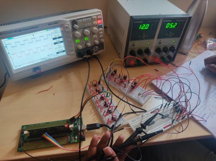
With the help of DSP-C2000 interface and IR-2113 driver circuit,wecangenerateswitchingpulsesof20kHzforIGBT (asshowninFigure14)(Alsocompletehardwaresetupof AFEDisshowninFigure13).
UsingtheconstantV/Fmethodforinductionmotorclosed loop speed control, an active front end drive that is PWM based SPWM has been designed and implemented in this paper. MATLAB Simulink has been used to simulate the analysis.Basicallyspeedchangescenarioshavebeentaken intoconsiderationforassessingtheperformanceofPWMbasedconverters,whichincludesaspeedchangefrom800 rpmto1000rpmint=2.14secataconstanttorqueof30Nm.TheActiveFrontEndDrivecircuit,whichissimulatedin the Simulink Model MATLAB software, enables variable
Volume: 09 Issue: 09 | Sep 2022 www.irjet.net p-ISSN: 2395-0072 © 2022, IRJET | Impact Factor value: 7.529 | ISO 9001:2008 Certified Journal | Page534
International Research Journal of Engineering and Technology (IRJET) e-ISSN: 2395-0056
Volume: 09 Issue: 09 | Sep 2022 www.irjet.net p-ISSN: 2395-0072
speed control of a three-phase induction motor by controllingthemotor'sspeed.Besidesthat,withtheaidof activelyobtainingafixedDCvoltageof800VandaTHDof 2.33%.
[1] M. Liserre, F. Blaabjerg and S. Hansen, "Design and control of an LCL-filter-based three-phase active rectifier,"inIEEETransactionsonIndustryApplications, vol. 41, no. 5, pp. 1281-1291, Sept.-Oct. 2005, doi: 10.1109/TIA.2005.853373.
[2] Siva Prasad, J. S.AU - Bhavsar, TusharAU - Ghosh, RajeshAU -Narayanan,G.PY 2008DA -2008/10/01 SN -0973-7677UR -https://doi.org/10.1007/s12046008-0045-y DO - 10.1007/s12046-008-0045-y, IDSivaPrasad200
[3] TY - JOUR ,AU - Chaudhary, Madhuri, AUSuryawanshi, Hirala, AU- Renge, Mohan, PY2012/01/01SP - 1EP - 10T1 - A three-phase unity powerfactorfront-endrectifierforACmotordriveVL5 DO -10.1049/iet-pel.2011.0029, JO - Power Electronics,IET
[4] R. Mathew, N. Agarwal, M. Shah and P. N. Tekwani, "Design,modellingandsimulationofthree-phasefrontend converter for unity power factor and reduced harmonics in line current," 2013 Nirma University International Conference on Engineering (NUiCONE), 2013,pp.1-6,doi:10.1109/NUiCONE.2013.6780145.
[5] MSaleem, Naziya andT. M. ThamizhThentral.“Vector ControlofActiveFront-EndRectifierforElectricMotors underUnbalancedCondition.”(2015).
[6] International Journal of Scientific & Engineering Research,Volume4,Issue6,June-2013322ISSN22295518AswathiG,SNalini,R.SudeepKumar
[7] V.Selarka,P.Shah,D.J.VaghelaandM.T.Shah,"Close loopcontrolofthreephaseActiveFrontEndConverter using SVPWM technique," 2016 International Conference on Electrical Power and Energy Systems (ICEPES), 2016, pp. 339-344, doi: 10.1109/ICEPES.2016.7915954.
[8] Y. V. Pavlova and B. V. Grigorii, "The synthesis of a control system of the active rectifier," 2018 IEEE ConferenceofRussianYoungResearchersinElectrical andElectronicEngineering(EIConRus),2018,pp.941944,doi:10.1109/EIConRus.2018.8317244.
[9] VolumeVII,IssueI,January2018,InternationalJournal ofLatestTechnologyinEngineering,Management,and AppliedScience(IJLTEMAS)|ISSN2278-2540
2022, IRJET | Impact Factor value: 7.529 | ISO 9001:2008 Certified Journal | Page535