International Research Journal of Engineering and Technology (IRJET) e-ISSN:2395-0056

Volume: 09 Issue: 09 | Sep 2022 www.irjet.net p-ISSN:2395-0072
International Research Journal of Engineering and Technology (IRJET) e-ISSN:2395-0056
Volume: 09 Issue: 09 | Sep 2022 www.irjet.net p-ISSN:2395-0072
1Department of Electrical and Electronics Engineering, Dr. Ambedkar Institute Of Technology, Bengaluru 560056 2Assistant Proffesor in Electrical and Electronics Engineering, Dr. Ambedkar Institue Of Technology Bengaluru 560056 ***
Abstract- The purpose of this paper is to design a quadratic boost converter (QBC) with the help of MATLAB-SIMULINK. The BLDC motor is made run using the quadratic boost converter. Numerous industries, including aviation, automation, industrial process control, precise machine tools, automotive electronics, and residential applications are using these motors extensively. The pulse width modulation (PWM) current controller technology is used in the paper to effectively control the speed of a BLDC motor. It is noted how the BLDC motor behaves in terms of speed and torque as well as the current and voltage components of the inverter. An elaborate explanation about quadratic boost converter for application of BLDC motor is shown. Here quadratic boost converter used for the application of BLDC motor simulation is done in MATLAB - SIMULINK software and in hardware also it is implemented.
Key Words: Quadratic boost converter (QBC), Three phase inverter, MOSFET, Aurdino UNO, Brushless dc motor (BLDC) etc…
Inthemajorityofapplicationswithlowpowerdemands,thedemandfor distributingdc-dcelectricity,high-frequency powerconversioniscontinuouslyrisingdaybyday.Thedevelopmentofconvertersforpoint-of-loadapplicationsisgiven more consideration by designers, with a focus on achieving objectives including greater power density, improved conversion efficiency at full load, and less electromagnetic interference (EMI). The design challenges for the application engineerare:(i)formulationofnon-isolatedtopologiesfreeoftransformers;(ii)minimumripplestogether withminimal requirement in L, C components; and (iii) reduction in the size of the filtering components together reduced severity/impact of electromagnetic interference. Multiple point-of-load converters are increasingly used in low power distribution systems (EMI). High-frequency switching is commonly used to create point-of-load converters, which are morecompact,lighter,and havehigherpowerdensitiesthankstothedevelopment oflowloss magneticmaterials.Many power electronic converters, or dc-dc conversion systems, that can generate stable voltages to drive dc loads have been reported in the literature. They can be broadly categorised as: (i) bucking-based circuits, (ii) boosting circuits, and (iii) buck-boostandotherrelativelyhighconvertercircuits.Theseconvertercircuits haveabroadrangeofuses,including:(i) specialised low-power integrated circuits; (ii) powering small automotive devices or loads; (iii) complex loads like biomedical equipment; and (iii) internet, wide area network, and local area network services, and (iv) equipment for defence, spacecraft power systems, and communications power supply systems. Commonly used in front-end power processing and power factor applications are boosting dc-dc converters. To generate greater load voltages from low voltagedcbatteries,pointofloadconvertersareusedinback-endapplications.Toachievehighvoltagegain,thestandard boost dc-dc converter must be powered at a high duty ratio, but the related operation may not be practical from an efficiencystandpoint.
An ordinary Boost Converter (BC) has several switching properties that increase I2R losses make them unsuitable for useinhigh-powersectorswheregreatefficiencyisthekeytosuccess.As aresult,theQuadraticBoostConverter(QBC),a cascaded version of two standard boost converters with one switch acting as a MOSFET to lower losses and boost efficiency,ispresented.Lowsaturationlevelsandunsteadyvoltagecontrolaredrawbacks.
An inverter, transforms a DC amount into an AC amount. By adjusting the duty cycle frequency of the voltage source inverter,wemayalterthefrequencyofaoutputvoltages,whichmayhaveaconstantorvariablefrequency.Theacvoltage outputtodcinputvoltageratioisknownastheinvertergain.Anefficientinverterwillhavesinusoidaloutputvoltages.An
International Research Journal of Engineering and Technology (IRJET) e-ISSN:2395-0056
Volume: 09 Issue: 09 | Sep 2022 www.irjet.net p-ISSN:2395-0072
ordinaryBoostConverter(BC)hasseveral switchingpropertiesthatincreaseI2Rlossesmakethemunsuitableforusein high-power sectors where great efficiency is the key to success. As a result, the Quadratic Boost Converter (QBC), a cascaded version of two standard boost converters with one switch acting as a MOSFET to lower losses and boost efficiency,ispresented.Lowsaturationlevelsandunsteadyvoltagecontrolaredrawbacks.
An electronically commutated DC motor without brushes is referred to as a BLDC motor. The synchronous motor's speedandtorquearecontrolledbythecontrollerbysendingshortburstsofcurrenttothemotorwindings.BLDCmotors areveryeffectiveatgeneratingalotoftorqueacrossspeedrange.Inbrushlessmotors,theproblemofattachingelectricity to the armature is resolved by moving permanent magnets with a fixed armature. Transportation based on electronics gives a wide range of options and adaptability. They are renowned for their ability to retain torque at rest and for their silentoperation
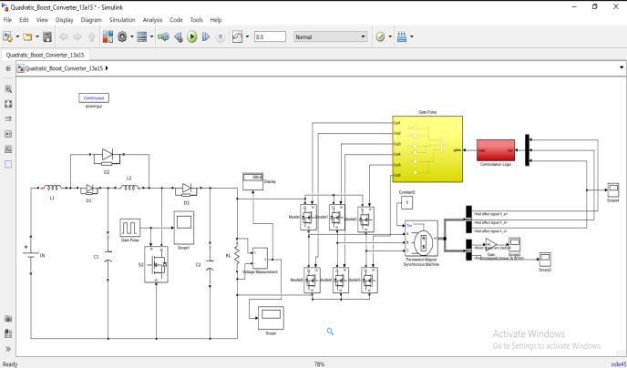
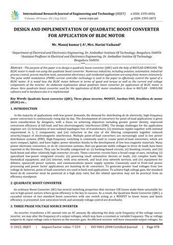
Thesystem'simplementationblockdiagramshowsaBLDCmotor,aVSIinverter,aDCtoDCconverter,andacontroller, orBLDCmotorcontroller,tomanagethemotor'sbehaviourandfunctioning.TheQBCisshowninpreviouspictureasaDC supplyconverterthatreplacesthenormalconverterwitha QBC.Switches,inputRippleandoutputrippleareallreduced inthecircuitbyusingaQBC.TheoutputoftheQBC isthensenttotheinverter,whichgeneratesaconstantoutputtorque bysequentiallyswitching themotor'sstator windings, resulting in a constantoutputpower. The motor controller usesa hall effect sensor to determine the speed and location of the motor. The whole simulation diagram of a solar power suppliedBLDCisshowninthefollowingimage.AspecificloadapplicationwasdrivenbyaBLDCmotorinthesimulation model.
Fig-2: SimulationoftheBlockdiagram
International Research Journal of Engineering and Technology (IRJET) e-ISSN:2395-0056
Volume: 09 Issue: 09 | Sep 2022 www.irjet.net p-ISSN:2395-0072
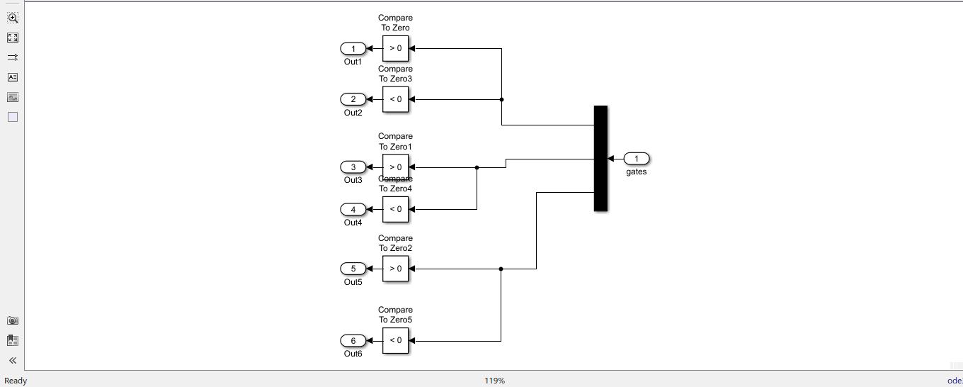
Fig-3: GatePlusecircuit
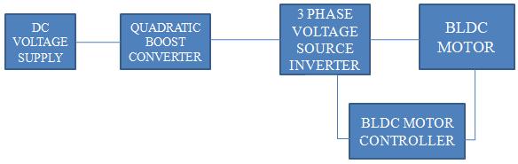
Fig-4: CommutationLogiccircuit
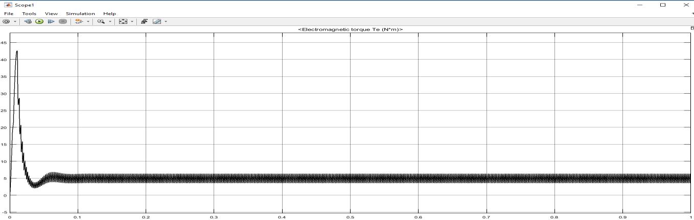
Dutycycle(x-axis),Torque(y-axis)
Fig-5: Electromagnetictorque(Te)
International Research Journal of Engineering and Technology (IRJET) e-ISSN:2395-0056
Volume: 09 Issue: 09 | Sep 2022 www.irjet.net p-ISSN:2395-0072
Dutycycle(x-axis) Torque(y-axis)(Nm) 0.01 43 0.03 2 0.05 7 0.1 5 0.5 5
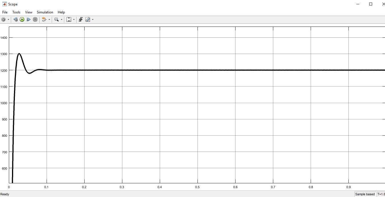
Dutycycle(x-axis),Rotorspeed(y-axis) Fig-6: Rotorspeed(wm)
Dutycycle(x-axis) Rotorspeed(y-axis)(Wm) 0.02 1300 0.05 1170 0.1 1200 0.2 1200 0.9 1200
International Research Journal of Engineering and Technology (IRJET) e-ISSN:2395-0056
Volume: 09 Issue: 09 | Sep 2022 www.irjet.net p-ISSN:2395-0072
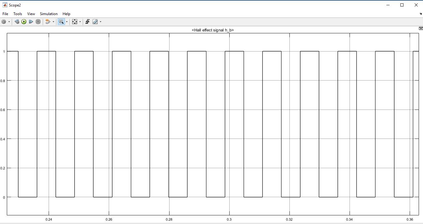
Fig-7: Halleffectsignal
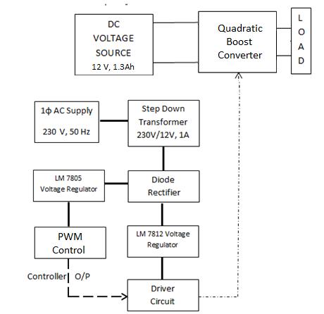
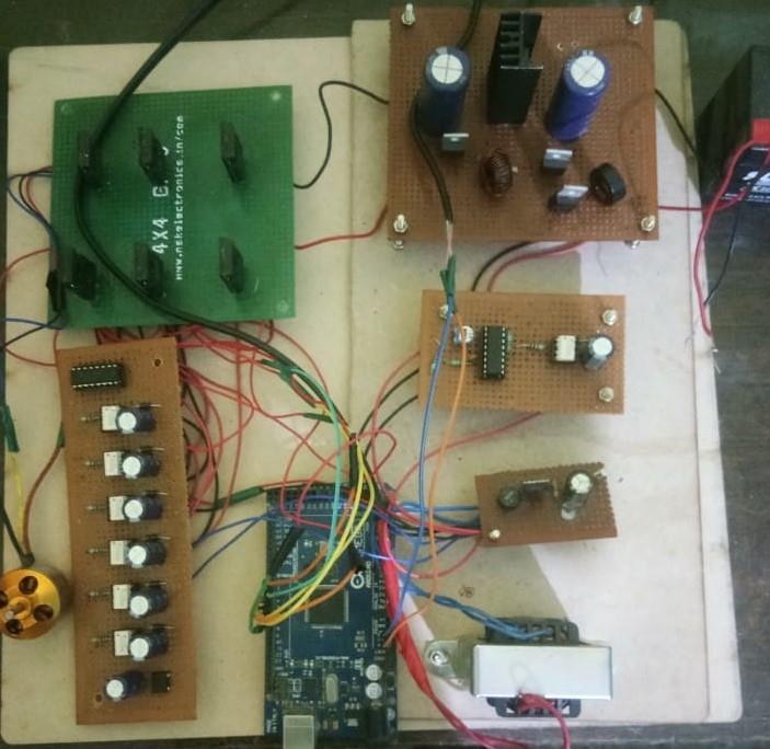
Toconvertthevoltageratioofthestepdowntransformer,whichis230/12V,1A, 50Hz,toDCvoltageandcontrolit,a singlephaseACsupplyof230V,50Hz,isused.The12Vacvoltageischangedto12VDCvoltageusingadioderectifier.The 5Vand12Vvoltageregulatorsreceivetherectifieddcvoltage.
Thedrivercircuitisgivena 12Vregulated dcsupplyso thatitmaydrive the Power Electronicswitchesofthesuggested inverterasinaccordancewiththegatepulsesproducedbythecontroller.
International Research Journal of Engineering and Technology (IRJET) e-ISSN:2395-0056
Volume: 09 Issue: 09 | Sep 2022 www.irjet.net p-ISSN:2395-0072
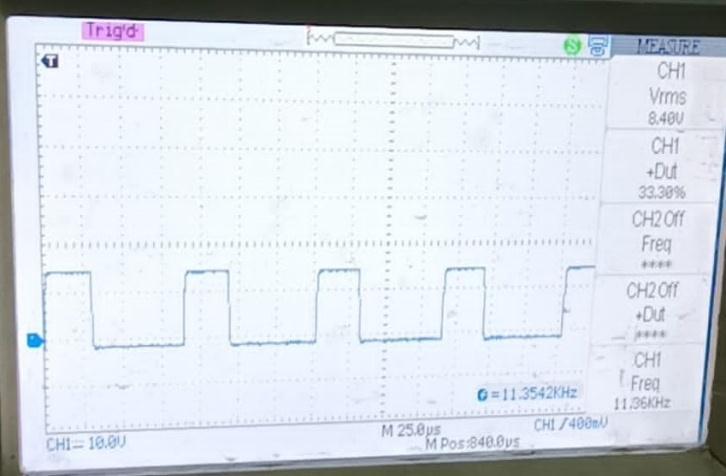
Thequadraticboostconverterispoweredbya12V,1.3Ahbatteryandhasa100resistiveload.Fortheswitch'sgate terminal,10KHzpulsesareoffered.
Fig-10: PulseofMOSFET
International Research Journal of Engineering and Technology (IRJET) e-ISSN:2395-0056
Volume: 09 Issue: 09 | Sep 2022 www.irjet.net p-ISSN:2395-0072
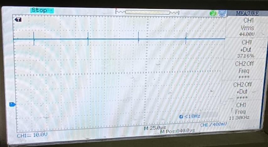
Fig-11:
Theloadvoltageisaround44Vwhichis3.67timeshigherthanthatofinputbatteryvoltageforthedutyratio0f33%.
Ithas been noted thattheinput voltage given in boththe hardware and softwaresituationsis around12V. Originally rated at 50 W, the device's power consumption has decreased to about 32W as a result of loss in the hardware implementation.Inboththehardwareimplementationandsimulation,theoutputvoltageincreasedbyafactoroffourto 48 V, which is exactly twice the 24 V target value for a traditional boost converter. In both instances, the switching frequencywassetat50kHz,whichisrecommendedforQBC’swithefficiencyandhighgain.TheBLDCmotor madetorun byquadraticboostconverterusingthethreephaseinverterforthepowerof32W.
[1]. B.Chandra Krishna, M.Nageswara Rao “Speed Control of BLDC Motor using Modified Buck Boost Converter” IEEE TransactionsonPowerElectronics,vol.24,no.5,pp.1198–1208,May2019.
[2]. Ashirvad M and Rupesh K C “Quadratic Boost Converter for Grid-Connected MicroInverter” IEEE Trans. Power Electronics,vol.30,no.3,pp.1488-1498,March.2019.
[3].M.Veerachary“DesignandAnalysisofaBoostConverter”IEEETransactionsonIndustrialElectronics,vol.56, issue6, pp.2203-2212,June2018.
[4].KemalKayaandYakupHames“AQuadraticCascadeDC/DCBoostConverterDesign”IEEE Trans.PowerElectronic.vol.18,no.1,pp.164–172,Jan.2016.
[5]. Selva Kumar. R, Vignesh.C. J, Gayathri Deivanayaki. V. P. “Design and Comparison of Quadratic Boost Converter with BoostConverter”IEEETrans.Ind.Appl.,vol.32,no.3,pp.518–525,2017.
[6]. Mustafa İnci “Design and Analysis of Quadratic Boost Converter with Inductor-Capacitor-Diode Voltage Multiplier Circuit”IEEETrans.Ind.Elect.,vol.50,no.5,pp.962–981,Oct.2018.
[7]. Angalaeswari S, Deepa.T, Subbulekshmi.D, Krithiga S, Pramit Ghosh, Aniket Kumar, Mutthi Karunanidhi, “Design and executionofQuadraticBoostConverter(QBC)inRenewabeEnergySynergies”AppliedPowerElectronicsConferenceand Exposition,2018.APEC2018.Twenty-ThirdAnnualIEEE,May2018,pp.973-979.
International Research Journal of Engineering and Technology (IRJET) e-ISSN:2395-0056
Volume: 09 Issue: 09 | Sep 2022 www.irjet.net p-ISSN:2395-0072
[8].S.AlirezaModaberi,BabakAllahverdinejad,MohamadRezaBanaei,“AQuadraticHighStep-up DC-DC BoostConverter
BasedonCoupledinductorwithSingleSwitchandContinuousInputCurrent”IEEETransactionsonPowerElectronics,vol. 29,no.9,pp.4684-4692,2019.
[9].M.S.Aspalli, FarhatMubeenMunshi,Savitri.L.Medegar“SpeedcontrolofBLDCMotor withFourSwitchThreePhaseInverterusingDigitalSignalController”IEEETrans.PowerElectron.,vol.18,no.1,pp.164–172,Jan.2016.
[10] K.I.Hwu,W.C.Tu,"Voltage-boostingconverterswithhybridenergypumping,"IETPowerElectron.,vol.5,no.2,pp. 185-195,Feb.2017.
[11] Shiyu Zhang, Jianping Xu, Ping Yang, “A single-switch high-gain quadratic boost converter based on voltage-lifttechnique”,Proc.ofIEEEIPEC,2012,pp.71-75.
[12]K.I.Hwu,Y.T.Yau,“AKYboostconverter,”IEEETrans.onPowerElectron.,vol.25,no.11,pp.2699-2703,Nov.2019.