International Research Journal of Engineering and Technology (IRJET) e-ISSN:2395-0056

International Research Journal of Engineering and Technology (IRJET) e-ISSN:2395-0056
Abstract -Propeller shaft is s very important component inautomobile,whichisusedforthetransmissionofpower generated by the engine to the wheels. The power transmission takes place from the engine to the wheels mainlydependsupontheweightofthe propellershaft, as the weight increases transmission capacity of the shaft decreases. To overcome this, steel shaft is replaced with the single piece composite shaft. When we use composite material the weight of the shaft decreases as a result the weight of the automobile also decreases. It can be achieved without an increase in cost and a decrease in qualityandreliability.
Keywords: composite propeller shaft, weight reduction E-glass/epoxyUD, carbon/epoxyUD,
The present research work focuses on the design of an light weight propeller shaft using composite materials. now a day all automobiles(which are having front engine, rear wheel drive)have the transmission shaft as shown in fig.1. two -piece propeller shaft increases the weight of propeller shaft which is not desirable in today’s market. the reduction in weight of the propeller system is advantageous in overall weight reduction in automobiles. Whichisahighlydesirablegoalofthedesignengineer.
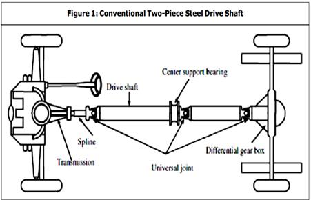
To replace conventional steel material two piece three universaljointdriveshaftwithcompositematerials.
1.2
Lowdensity
Highspecificstrength
Highspecificmodulus
Highthermalconductivity
Goodfatiguemodulus
Controlofthermalexpansion

Highabrasionandwearresistance
Composite are needed because modern applications require materials with strange combination of properties like low stiffness, high strength, abrasion and impact resistance.
For achieving the objective of the work a flow chart is prepared which shows various steps taken in to consideration.
ReverseEngineering (TotakedimensionfromtheexistingPLS)
CADModelGeneration(Fromansysmodelling)
StaticAnalysis(WithConventionalSteel andCompositematerialinANSYS)
Result (Von-misesstress,Totaldeformation, Maximumprinciple stress,Maximumshear stress,weightsavingpercentage)
1. Todecreasetheweight. 2. Toincreasethetorquetransmissioncapacity. 3. Tostudyinducedstressinpropellershaft
4. Tostudydynamicbehaviorofpropellershaft.
ResultComparison (Materialselectiononbasisofbetterstrengthweight)
Volume: 09 Issue: 09 | Sep 2022 www.irjet.net p-ISSN:2395-0072 © 2022, IRJET | Impact Factor value: 7.529 | ISO 9001:2008 Certified Journal | Page442
Assistant Professor, mechanical engineering Dept. of Dr. APJ Abdul kalam UIT,RGPV Jhabua M.P.International Research Journal of Engineering and Technology (IRJET) e-ISSN:2395-0056
Volume: 09 Issue: 09 | Sep 2022 www.irjet.net p-ISSN:2395-0072
1. outerdiameter d 70mm
2. innerdiameter d 56mm
3. thickness of the propellershaft t 7mm
4. lengthofthepropeller shaft l 1800 mm
4.1.1 CAD Modeling: CreationofCADmodelbyusingany of the CAD modeling tools like Pro/Engineer, Catia, UG, Solid Edge, for creating the geometry of the part/assemblyofwhichneedstoperformFEA.
4.1.2 Importing the Geometry to FEA Package: Runthe FEA package and import the CAD model/geometry in IGESformatintotheFEApackage.
4.1.3 Defining Material Properties: Inthisstepwehave to choose the material which we are going to use for the FEA analysis of part/geometry. Material can be selected from FEA package engineering materials section, if particular is not available in the library than we can add the new materials with valid material properties in the materialsection.
4.2.1Meshing: Meshing is a critical and most important operation in FEA. In this operation the CAD model/geometry is divided into large numbers of small pieces called elements. The analysis accuracy and durationdependsonmeshsizeofthegeometry. Withthe increase in mesh size the finite element analysis speed increase but the accuracy decrease. Mesh convergence testcanbeperformedtoselectthecorrectmeshsize.
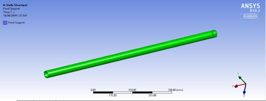
4.2.2 Defining Boundary Condition: Defining boundary condition is the most important process in FEA analysis becauseresultsoftheFEAanalysisisdependonthegiven boundary conditions, so this section require lot of study togivingcorrectboundaryconditions.Wehavetotellthe FEApackagewherewewanttoapplyloadsandwherewe wanttofixthepart.
This is the solution phase. In this section we tell the FEA package to solve the problem for the defined material properties, mesh size and boundary conditions. In this section we can select the parameters like stress, strain, deformation,contacttool,andcangettheresultsforthese parametersinsingleanalysis.
Post-processing provides the tool with easy-to-use powerful result visualization Features. It provides an in depthviewofdatawithvisualizationtoolssuchascutting planes,contouring,streamlines,lineplots,dataprobesand animation. At the last finally the results could be studied on the post processing stage, where different physical variables such as stress, strain and pressure would be displaced and interpreted. can be viewed in various formatssuchasgraph,valueanimationsetc.
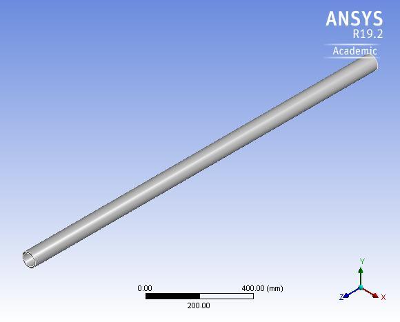
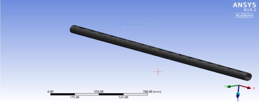
ANSYS is a feature-based, parametric solid modeling system with many extended design and manufacturing applications. Three dimensional model of propeller shaft are prepared by using 3D modeling software ANSYS as showninfig.5.1
5.1
5.1Introduction
In this section application of FE modelling is discussed, FEAtoolisthemathematicalidealizationofrealsystem.Is a computer based method that breaks geometry into element and link a series of equation to each, which are thensolvedsimultaneouslytoevaluatethebehaviorofthe entire system. It is useful for problem with complicated geometry, loading, and material properties where exact analytical solution are difficult to obtain. The static in FE analysisiscarriedoutinthissection.FEMgeneralpurpose softwareANSYS-19.2isusedfortheanalysisofcomposite materialpropellershaft.
International Research Journal of Engineering and Technology (IRJET) e-ISSN:2395-0056
Volume: 09 Issue: 09 | Sep 2022 www.irjet.net p-ISSN:2395-0072
CAD modeling of the composite propeller shaft componentsisthefirststepoffiniteelementanalysis.CAD modeling of the composite propeller shaft using conventionalsteelEN45andcompositematerialshasbeen done according to the dimensions suggested by Ansys software
CAD model of the composite propeller shaft is saved as WBPJformatinansysmodelling. Then,thisWBPJCADfile importedintoANSYS-19.2forfurtheranalysis.
There are three composite propeller shaft on which the analyses are going to perform, one is structural steel propeller shaft and other two are composite propeller shaft. The mechanical properties of the structural steel material beingusedinthis analysisareshowinTable no5.1 and the mechanical properties of composite material whichcanbetakenasperANSYS-19.2materiallibrary.
Table 5.1 Mechanicalpropertiesof Structuralsteel
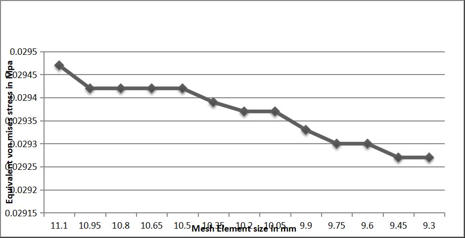
Fig-5.2VariationinvonMisesstressvaluewithrespectto themeshsize
linear elements are used for all the components of composite propeller shaft. linear elements better approximate the shape with minimum error as compared tobrickelements.Accordingtothemeshconvergencetest, Size of the linear elements are 9.3 mm for all the components of composite propeller shaft a total no. of 30885 nodes and 4900 elements are generated after the meshing. Meshed composite propeller shaft model is showninfig.5.3
A check point is tested on the assembly by using mesh convergence test in order to simplify and justify the analysis result. In this process the von- mises stress level is tested on assembly by taking different size of element during meshing. With the assistance of ANSYS-19.2 software, the respective mesh sizes with corresponding von- mises stresses are given in the fig. 5.2. The moment value is same for each mesh size 9.3 mm. We observed that below the mesh size of 11mm there are small variationsinthevalueofvon-misesstresses.Sothemesh size of 9.3mm is taken in this study for meshing of the compositepropellershaft.
International Research Journal of Engineering and Technology (IRJET) e-ISSN:2395-0056
Volume: 09 Issue: 09 | Sep 2022 www.irjet.net p-ISSN:2395-0072
comparison of thickness verses stress for steel and composite propeller shaft. It is observed that the stresses increase linearly with the applied load maximum. Maximum stresses are exhibited by Carbon epoxy and minimumbytheE-Glassepoxy.
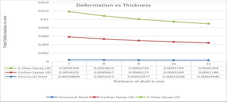
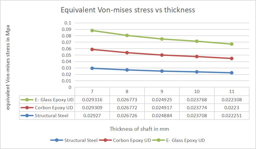
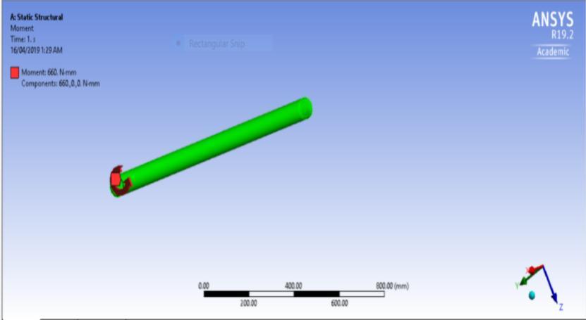
Fig.5.5Applyingmomentoneendofpropellershaft
Staticanalysisofthecompositepropellershaft(structural steel and composite material) is performed using ANSYS19.2 software to find the von-mises stresses, maximum principal stresses, equivalent elastic strain and deflection. The Analysis involves the following discretization called meshing, boundary conditions . A virtual model of each propeller shaft is modeled separately, and then it is assembled together using ansys modelling (figure 5.1)This model is then imported into ANSYS- 19.2 for conducting static analysis Same model is used for the static analysis with three different materials structural steel, E-glass/epoxy, and carbon/epoxy . These materials are selected in the Ansys-19.2 software by inserting the appropriatematerialproperties.
Inthissectionthestructuralsteelandcompositepropeller shaft will be analyzed to see the various results from the static analysis The software used to perform the analysis is ANSYS -19.2,The different comparative results of steel propellershaftandcompositepropellershaftareobtained topredicttheadvantagesofcomposite foravehicle.
Von-Mises stresses are widely used to check whether the designwillwithstandthegivenload conditions,usingthis information we can say design will fail, if the maximum value of von-Mises stress induced in the material is more than yield strength of the material. In this study it can be seen that the von-Mises stress is maximum towards the fixedendofthecompositepropellershaft,andthevalueis less than yield point value of structural steel and considered composite materials. So, the design of composite propeller shaft is safe. Figure 6.1 shows the
Figure-6.1Thicknessvsequivalent(von-Mises)stress
The rate of deformation is a function of the material properties, and the applied load depending on the magnitude of the applied stress and its duration. Figure6.2showsthecomparisonofthicknessversesdeformation ofbothsteelandcompositepropellershaft.Itisfoundthat the deformation in composite propeller shaft is higher than steel propeller shaft for the given thickness conditions. Maximum deformation is exhibited by E-Glass epoxyandminimumbytheStructuralSteel.
Figure6.2Thicknessvstotaldisplacement
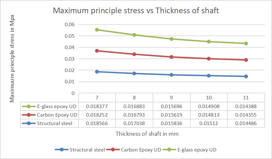
According to maximum principle stress criterion the materialofthecompositepropellershaftwillbesafe,ifthe ultimate tensile strength of the material is greater than
International Research Journal of Engineering and Technology (IRJET) e-ISSN:2395-0056
maximumprinciplestress.Figure-6.3showsthedeviation of principle stress is very low at maximum thickness condition and the deviation of principle stress increases when the magnitude of applied thickness decrease. Maximum principal stresses are exhibited by Carbon epoxyandminimumbytheStructuralsteel.
Material Mass of the propellershaft % weight saving
1 SteelEN45 19.576kg -
2 E-glass/epoxy 4.9876kg 74.52%
3 Carbonepoxy 3.8404kg 80.38%
Table6.1%ofweightsavingfordifferentmaterials
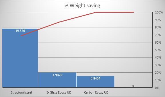
Figure6.3thicknessvsmaximumprincipalstress
6.4 Maximum Shear Stress
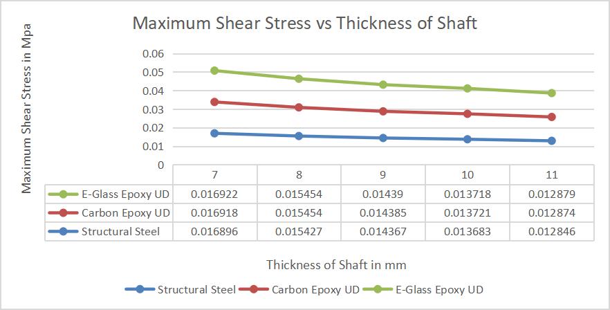
Figure 6.5 shows the comparison of propeller shaft mass (Kg)forsteelandothercompositematerials.Fromthefig. 6.5 it is easily observed that the weight reduction composite propeller shaft E-glass/epoxy mass is 4.9876 kg, carbon epoxy mass is 3.8404 kg. Table shows the % savingofweightbyusingcompositesinsteadoffstructural steel.
Fig.6.5Comparisonof%weighsavingofdifferent propellershaft
In this research work a propeller drive shaft is designed and analyzed for Ashok Leyland engine, truck model 6DT120.The propeller drive shaft is designed for the torque of 660N-mm. Theoretical calculations have been calculated for propeller drive shaft dimensions at varying thickness,bymathematicalapproach.Inthisworkanalysis has been done by taking materials Steel , E-Glass/Epoxy UD, Carbon/Epoxy UD. Static structural analysis are conductedonpropellerdriveshaft.
Volume: 09 Issue: 09 | Sep 2022 www.irjet.net p-ISSN:2395-0072 © 2022, IRJET | Impact Factor value: 7.529 | ISO 9001:2008 Certified Journal | Page446
-The generated stresses in the composite propeller drive shaft are much lower than that of the yield stresses and thestressesgeneratedinstructuralsteel.
-The composite propeller drive shaft is lighter and more economical than the conventional steel shaft with similar designspecifications.
-It is observed that the weight of the composite propeller drive shaft made of E-Glass/Epoxy UD, is reduced by 74.52% compared to made of steel, by using material
International Research Journal of Engineering and Technology (IRJET) e-ISSN:2395-0056
Volume: 09 Issue: 09 | Sep 2022 www.irjet.net p-ISSN:2395-0072
Carbon/Epoxy UD it is reduced by 80.38% compared to madeofsteel.
-It is observed that the composite material shows more deflection and strain energy than that of steel, for less weight of the propeller drive shaft mechanical efficiency willbeincreased.
Deformationinmm
Material Thicknessofshaftinmm
S. n o.
7mm 8mm 9mm 10mm 11mm
1 Structur alsteel 0.0003 8845 0.0003 551 0.0003 2977 0.00031 006 0.0029 446
2 E-Glass /Epoxy UD
0.0059 764 0.0054 633 0.0050 736 0.00477 04 0.0045 304
3 Carbon/ Epoxy 0.0054 332 0.0049 667 0.0046 125 0.00433 69 0.0041 186
-Obtained results from the static analysis Carbon/Epoxy UD is better than E-Glass/Epoxy UD because its stresses arelessthanother.
-Using FEM software tool like ANSYS-19.2 Workbench prove the reliability of the validation methods based only on simulation, thereby saving time, and help to understand behavior of the composite propeller drive shaft.
Following future recommendations can be added as an extension to this work:As analysis of composite propeller driveshaftandsteelpropellerdriveshaft
is validated by comparing previously published data, so it is needed that one can perform experimental validation with manufacturing of actual prototype of composite propeller drive shaft. As this analysis is under static load condition, so one can go for dynamic loading condition. Dynamic , Model & Vibration analysis of propeller shaft mayalsobedone.
1.Atul Kumar Raikwar, Prof. Prabhash Jain & Raj kumari Raikwar -International Journal of Engineering DevelopmentandResearch.Volume4,Issue4ISSN:23219939-2016.
2.6-Muni kishore, Jaligam Keerthi, Vinay kumarInternational Journal of Engineering Trends and Technology,Volume38Number6-August2016
3.Sridhar, Dr. R. Mohan, R. Vinoth Kumar -International Journal of Scientific &Engineering Research, Volume 7, Issue5,May-2016,ISSN2229-5518.
4.Dr. R. Ganapathi, Dr. B. Omprakash, J.Vinay KumarInternational Journal of Latest Engineering Research and Applications, Volume – 02, Issue – 11,November 2017, PP –24-28,ISSN:2455-7137.
5.Ashwani Kumar, Neelesh Sharma, Pravin P PatilProceedings of the World Congress on Engineering 2017 VolIIWCE2017,July5-7,2017,London,U.K.
6. Vinodh Kumar S, Sampath V and Baskar P - Research Journal of Recent Sciences. Vol. 4(9), 9-15, September (2015),ISSN2277-2502
2022, IRJET | Impact Factor value: 7.529 | ISO 9001:2008 Certified Journal | Page447