International Research Journal of Engineering and Technology (IRJET) e-ISSN: 2395-0056

Volume: 09 Issue: 09 | Sep 2022 www.irjet.net p-ISSN: 2395-0072
Abstract - Inrotorshaftassemblyofhermeticallysealedreciprocatingcompressor,thereisinterferencefitbetweenrotorand shaft. To obtain this interference fit various methods are used. Without the use of extra mechanical fastening systems, interference-fittedjointsareanefficientandcost-effectivewaytoassemblecomponents.Aninterfacepressureisestablished duringassemblybypress-fittingorashrink-fittingassemblyprocessasaresultofadimensionalmisfitbetweenthetwoparts, whichisfrequentlyinashaftandrotor.Becauseoffrictionalresistance,thejointisabletowithstandaxialforcesandtorques. Thetraditionalmethodforachievingashrinkfitbetweentherotorandshaftisinductionheating.Thisprocessrequiresheating equipmentandhigherenergyconsumption,thiswillincreasethemanufacturingcostofthecompressor.Duetothelimitationsof inductionheatingprocess,thereisaneedtoidentifyanddesignanalternativeoptionsforachievingshrinkfitinrotorshaft assemblyincosteffectivemanneryetensuringthedesiredquality.Thispaperpresentsthestudyofcurrentandproposed assemblyprocedureusedtogetrotor-shaftassemblyinhermeticallysealedreciprocatingcompressor.Inthisstudy,factorsthat affectaninterference-fittedjoints'abilitytofunctionproperlyaregroupedunderafewgeneralheadings,including:coefficientof friction,coefficientofthermalexpansion,surfaces,thegeometry,frictionalforce,torque,tangentialforce,materials,loading,and lastlytheassemblymethodutilizedtocreatethejointbetweentherotorandshaft.
Keywords: Interference fit, , rotor shaftassembly,shrinkfitting,inductionheating,radial orinterfacepressure,torque, frictional force, tangential force.
1. INTRODUCTION:
Inrotorshaftassemblyofthehermeticallysealedreciprocatingcompressor,toachieveaninterferencefitbetweenrotorand shaft,shrinkfittingtechniquesaregenerallyused.Shrinkfittingtypicallyreferstotechniquesthatutilizethephenomenaof thermalcontractionandexpansiontoproduceaninterferencefit.Themostcommonmethodfordoingthisistoheattheouter component,causingittoexpandthermally.Thentwopartsfittogethereasily.Anincrediblytightjointformsaroundtheinner partwhentheouterpartcoolstoroomtemperatureandcontractsbacktoitsoriginalsize.Typically,metalswillexpandin responsetoheating.Soinductionheatingisgenerallyusedtoobtainshrinkfitinrotorshaftassembly.Inexistinginduction heatingprocessrotorisheatedfromoutsidesurfaceandthenheatistransferredfromoutsidetoinsidesurfaceofrotortoobtain thermalexpansionofrotorbore.Afterexpansion,rotorisshrinkfittedintotheshaft.Butthisprocessrequireshigherpower consumptionandhenceincreasesthemanufacturingcostofthecompressor.Soheatingfromtheinsidesurfaceoftherotorbore isthealternativeoptiontoachieveshrinkfitinrotorshaftassembly.
2. Rotor Shaft Assembly:
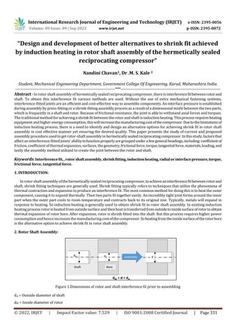
Figure1.Dimensionsofrotorandshaftinterferencefitpriortoassembling
dA =Outsidediameterofshaft
dM =Insidediameterofrotor
“Design and development of better alternatives to shrink fit achieved by induction heating in rotor shaft assembly of the hermetically sealed reciprocating compressor”
Nandini Chavan1 , Dr .M. S. Kale 2Student, Mechanical Engineering Department, Government College Of Engineering, Karad, Maharashtra India.
International Research Journal of Engineering and Technology (IRJET) e-ISSN: 2395-0056
Volume: 09 Issue: 09 | Sep 2022 www.irjet.net p-ISSN: 2395-0072
d=Diametricinterference
Figureshowsthedimensionsofrotorandshaftinterferencefitpriortoassembling.Interferencefitisalsoknownaspressfitor frictionfit,isafasteningmethodwheretwoparts,typicallycircularcrosssectionshape,arepushedtogether(oneintothe other)andkeptinplaceduetothepressurebetweenthem.Typically,theinnerpartwillhaveanominalouterdiameterslightly greaterthanthenominalinnerdiameteroftheouterpart,andwhenpushedorforcedtogetherthecontactfrictionforceskeep thepartsfrommovingrelativetoeachother Thelevelofinterferencedependsonthenegativedifferenceinnominaldiameters.
Shrink Fit Process
Obtaining shrink fit by heating from the inside surface of the rotor bore:
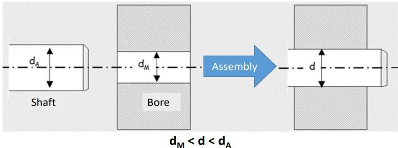
Theonlyviablewaytoheattherotorisusinganinductioncoilfromtheinsidesurfaceoftheoftherotorbore,thisheatallowsfor betterenergydeliverytotheassembly.Inthismethodheatingwillbeonlylocalheating.Aninductioncoilcanbeusedtoheatthe rotorbore.Thecoilisinsertedintotherotorboreandpowerisappliedforcertaintimetoreachtherequiredtemperaturefor heatingtherotorboreandtriedtoexpandtherotorboreandplacedontotheshaft.Thisprocessconsumeslesspoweras comparedtoheatingfromtheoutsidesurfaceofrotor.
Theoretical modelling of Thermal expansion:
Part Material Outsidediameter (mm) Inside Diameter(mm) Stack Height(mm) CoefficientofThermal expansion(mm/mm0c) Rotor Aluminium 60.3 19.5 63.5 23.1
Table1:Dimensionsandmaterialpropertiesofaluminiumrotor
DiameterincreaseofrotorborewhenbeingheatedorThermalexpansionofrotorboreiscalculatedas:
Δd=doαΔT
Where,
Δd=changeindiameterofrotorboreorthermalexpansion(mm)
do =insidediameterofrotoratinitialtemperature(mm)
α=coefficientofthermalexpansionofaluminum,23.1 10-6 (mm/mm0C)
ΔT=changeintemperature(0C)
Roomtemperature=27 0C
Originaldiameterof rotorbore(mm) Temperature (0C)
Thermalexpansionof rotorbore(mm) Increaseddiameterof rotorbore(mm)
19.5 50 0.01 19.51 19.5 80 0.023 19.523 19.5 100 0.032 19.53 19.5 150 0.05 19.55 19.5 200 0.07 19.57 19.5 225 0.089 19.58
Table2:TheoreticalmodellingofThermalexpansion
Factor value: 7.529 | ISO 9001:2008 Certified Journal | Page332
International Research Journal of Engineering and Technology (IRJET) e-ISSN: 2395-0056
Volume: 09 Issue: 09 | Sep 2022 www.irjet.net p-ISSN: 2395-0072
Experimental method for obtaining required thermal expansion of rotor bore by heating from inside surface of rotor bore:
RotorMaterial Rotoroutsidediameter(mm) Rotorinsidediameter(mm) Aluminium 60.3 19.5
Table3:Dimensionsofaluminiumrotorbore
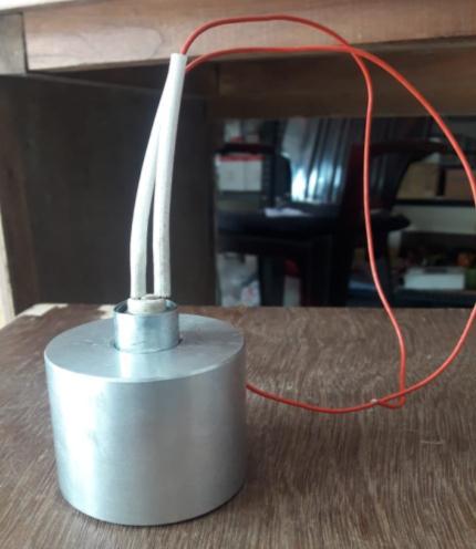
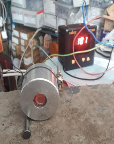
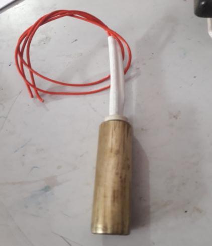
Process:A2KWcartridgeheaterrodisusedtoheattherotorbore.Therodisinsertedintotherotorboreandpowerisapplied fortimetoreachtherequiredtemperatureatwhichthermalexpansionofrotorboreisobtained.Inthisprocesstriedtoexpand therotorboreatvarioustemperature.Temperatureismeasuredbythermocouple.Thermalexpansionismeasuredbydigital verniercaliperhavingleastcountof0.01mm.
International Research Journal of Engineering and Technology (IRJET) e-ISSN: 2395-0056
Volume: 09 Issue: 09 | Sep 2022 www.irjet.net p-ISSN: 2395-0072
Experimental Result:
OriginalDiameterof rotorbore(mm)
Temperature(ºC) Thermal expansion(mm) Changeindiameterof rotorbore(mm)
19.5 50 0.03 19.53 19.5 80 0.06 19.56 19.5 100 0.08 19.58 19.5 150 0.18 19.68
Table4:Experimentalresultsofthermalexpansion
Temperature(⁰C)
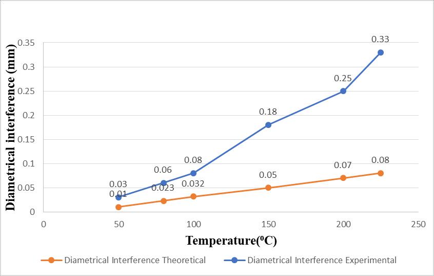
ThermalExpansion Theoretical(mm) Experimental(mm) 50 0.01 0.03 80 0.023 0.06 100 0.032 0.08 150 0.05 0.18 200 0.07 0.25 225 0.08 0.33
ComparisonofTheoreticalandExperimentalresult
Figure6.Acomparisonbetweentheoreticalandexperimentalmeasuredresults
2022, IRJET | Impact Factor value: 7.529 | ISO 9001:2008 Certified Journal | Page334
International Research Journal of Engineering and Technology (IRJET) e-ISSN: 2395-0056
Volume: 09 Issue: 09 | Sep 2022 www.irjet.net p-ISSN: 2395-0072
Reasons for getting difference between theoretical and experimental results:
Fromfigure,itisobservedthatthereisdifferencebetweentheoreticalandexperimentalexpansionvalues,itisbecause ofroleofheatingtimeingettingexpansion.
Inexperimentalmethod,expansionobtainedismorebecauseofheatingtimeisgettingmoreforeverytime. Moreheatenergyistransferredtomaterial,soexpansionismore.
Mathematical Modelling of Friction Force:
Frictionorfrictionalforceisdefinedastheforcethatresistsanobject’smotiononasurface.Theobjectcaneitherbestationary orinmotionrelativetothesurface.Frictionoccurswheretheobjectisincontactwiththesurface.Inotherwords,ittakesplace betweentwosurfaces,andhence,isacontactforce.
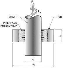
Figure7.SchematicofShrinkfitassembly
The“coulombfriction”modelisusedformodellingtangentialforcesbetweencontactsurfaces.Iftangentialforcesarelower thanfrictionforcesµN,theywillbeproportionaltotherelativedisplacementbetweenthecontactsurfaces.Iftheyarelarger, thecontactsurfacesstarttoslipandthetangentialforceswillequalthefrictionforces.Thisconditioniscalledas“macro-slip" model. Sotoavoidthisphenomenonincaseofrotorshaftshrinkfitassembly,frictionalforceshouldbegreaterthanthe tangentialforce.Thentherewillberelativedisplacementbetweenrotorandshaft.
ThecontactpressurebetweenrotorandshaftinvolvedininterferencefitisgivenbytheLame´sequation:
International Research Journal of Engineering and Technology (IRJET) e-ISSN: 2395-0056
Eo =Modulusofelasticityofrotor(Pa)
Ei =Modulusofelasticityofshaft Pa)
γ0=Poisson’sRatioforrotor
γi=Poisson’sRatioforshaft
Maximumfrictionalforcedevelopedduetocontactpressure:
FF = p ×2π×R×L×µ
Where, p =contactpressure(Pa)
R=Radiusofshaft(m)
µ=Coefficientoffrictionbetweenrotorandshaft
L=Lengthofcontact(m)
Tangentialforcegivenbymotor:
Torque=Tangentialforce×radiusofshaft
T=FT ×R
Where, T=Motorstartingtorque(Nm)
FT =TangentialForce(N)
R=Radiusofshaft(m)
Iffrictionalforceisgreaterthantangentialforcethenshaftcantransmitthespecifiedpowerofmotorandinterferencefitis suitableforrotorshaftassembly.
Conclusion:
Heatingfrominsideoftherotorborecanbeabetteroptionforheatingrotortogetquickerexpansionofrotorbore.
Incaseofheatingrotorbore,heatingwillbeonlylocalheating.Onlyrequiredpartisheatedandexpanded.
Thismethodgivespossibilityofavoidingcoolingofassembly,soitcouldremovecoolingoperationalltogether.
Future Scope:
Someopportunitiesforfutureworkonpresentdissertationworkareoutlinedasfollows:
Heatingfromborediametercanbeachievedbysuitablydesignedinductioncoilthatfitsintobore. Studytheeffectofvaryingthesizeandshapeoftheinductionheatingcoilincaseofexternalheatingoftherotor. Addasleeveofhighlyconductivematerialtotheinnersurfaceoftherotorsothatitexpandseasily.
References:
1. Fiji Toma, Optimization of rotor shaft shrink-fit method for motor using ‘‘Robust design,’’ Journal of Industrial EngineeringInternational(2018),pp.705–717
Volume: 09 Issue: 09 | Sep 2022 www.irjet.net p-ISSN: 2395-0072 © 2022, IRJET | Impact Factor value: 7.529 | ISO 9001:2008 Certified Journal | Page336
International Research Journal of Engineering and Technology (IRJET) e-ISSN: 2395-0056
2. Mitesh. S. Agrawal, Ankit. M. Rathi, Prof. Prashant. B. Shiwalkar, ‘Algorithm in Automated Press Fit for Rotor Shaft AssemblyofanInductionMotor’,IJIRSET,Vol.5,Issue11,November2016,pp.20143-20149.
3. NazımArda Eyyuboğlu, ‘Investigationofthe Parameters Affecting CrankshaftandRotor Interference Fit’, school of mechanicalengineering,2014,pp.1-10.
4. SomnathKolgiri,“StaticandDynamicAnalysisforRotorShaftofElectricMotor”,(2009),pp.1-17.
5. J.D.BookerandC.E.Truman,MEASURINGTHECOEFFICIENTOFFRICTIONFOR USEINSHRINK-FITCALCULATIONS, DepartmentofMechanicalEngineering,UniversityofBristol,UK,November2009,pp.7-13.
6. Truman,C.E.,andBooker,J.D.,‘‘AnalysisofaShrink-fitFailureonaGearHub/ShaftAssembly,’’EngineeringFailure Analysis14(4):557–572(2007).
Volume: 09 Issue: 09 | Sep 2022 www.irjet.net p-ISSN: 2395-0072 © 2022, IRJET | Impact Factor value: 7.529 | ISO 9001:2008 Certified Journal | Page337