International Research Journal of Engineering and Technology (IRJET) e-ISSN:2395-0056

Volume: 09 Issue: 09 | Sep 2022 www.irjet.net p-ISSN:2395-0072
International Research Journal of Engineering and Technology (IRJET) e-ISSN:2395-0056
Volume: 09 Issue: 09 | Sep 2022 www.irjet.net p-ISSN:2395-0072
1Assistant Professor, Department of EEE, Nitte Meenakshi Institute of Technology, Yelahanka, Bengaluru-560064
2PG student, Department of EEE, Nitte Meenakshi Institute of Technology, Yelahanka, Bengaluru-560064
3Assistant Professor, Department of EEE, Nitte Meenakshi Institute of Technology, Yelahanka, Bengaluru-560064 ***
Abstract: we are currently facing many issues related to shortage of fuel. Now we have to move towards electrical vehicle. people are not ready to use electrical vehicle over present petrol and diesel vehicles because of the cost as well as lack of availability of electric charging stations . Even though there are very few charging stations available, it is requires extra time for charging the vehicle. So, by considering this issue in view the design is proposed to create and handle the Electric Vehicles (EV), charging procedures based on the intelligent process. Due to the electrical power distribution limitation, Electric Vehicles charging should be performed in effective way. This proposed Smart Electric Vehicle Charging station having many advance features like it will automatically maintain the power from different source and automatic switch the source based on availability of the source. In this implementation we are using two different source, solar system, and main supply. The controller will automatic switch the source based on its priority. User will be able to see the source connected based on availability on the LCD display. Once charging will be completed, the device will automatically stop the charging and overcharging will not happen in electrical vehicle. This process is monitored by using Internet of Things (IoT). The proposed control system and their control functions aredoneinProteus8Professional.
their power production, PV cells are connected together to form larger units known as modules or panels. Modules can be used single or linked together to form arrays. Then, as a component of the complete Photo Voltaic system .One or more arrays will be connected to the electricity grid. Due to their modular construction, Photo Voltaic system systems may be created to meet any size of the electric power requirement. Arrays, Modules are simply one part of the PV system. In addition to the components that convert the direct current (DC) electricity generated by modules into the alternating current (AC) electricity needed to power all of the appliances in your home, systems also contain mountingstructuresthatguidepanelstowardthesun.
Anelectricallycontrolledswitchisarelay.Itconsistsofa number of input terminals for one or more control signals as well as a number of functioning contact terminals. Any number of connections in different contact configurations, such as making contacts, breaking contacts, or combinations of both, may be included on the switch. These are used when multiple circuitsneedtobecontrolledbyasinglesignalorwhena circuit has to be controlled by a separate low-power signal. An electromagnet is used in the typical relay designtocloseoropentheconnections
Keywords– Arduino UNO, NodeMCU, Electric Vehicle Charging, Proteus 8 Professional
A photovoltaic (PV) cell assembly mounted in a frameworkisreferredtoasasolarpanel.Sunpanelsuse solarenergytogeneratedirectcurrentpower.Acellisa single photovoltaic (PV) device. Typically, a single photovoltaic cell only generates 1 or 2 watts of power. Thesecellsarefrequentlythinnerthanfourhumanhairs and constructed of various semiconductor materials. To endure the elements for a very long time, cells are sandwiched between protective materials in a combination of glass and or plastics. In order to boost
A flat-panel display known as a liquid-crystal display (LCD)usespolarizersinadditiontothelight-modulating capabilitiesofliquidcrystals.Dependingonthepolarizer configuration, LCDs can display text with little information, often on (positive) or off (negative). It is distinguishedbytheabilitytocreateimagesusingliquidfilledcrystals.Thedisplayscreencontainsliquidcrystals illuminatedbyabacklightofsomekind.Electricvehicles requires a charging station to charge similar to the current fuel cars that require a petrol , and charging takes some time, so it will be better to charge the vehicles when it is parked. We are using two different sources, the solar system and the main supply for the chargingsystem,basedonInternetofthings technology, making the system user-friendly. One can upload the information on the cloud and simultaneously on the smartphones. The IoT is the finest monitoring tool for switching systems., providing more comprehensive
International Research Journal of Engineering and Technology (IRJET) e-ISSN:2395-0056
Volume: 09 Issue: 09 | Sep 2022 www.irjet.net p-ISSN:2395-0072
connectivity, an modified sensing, processing information, and greater flexibility. So, controlling the chargingofdevicesissimplewiththehelpofIoT.
[1] Stephen Lee, Srinivasan Iyengar, David Irwin, and Prashant Shenoy, In this paper, it is considered solar-powered charging station for an Electric Vehicle car-share service (such as ZipCar, Autolib). Usually, in the vehicle-sharing services, gasoline powered vehicles are most popular but with increase in popularity of electric cars, service providers may soon own more electric cars. In fact, some vehicle sharing services have Tesla models. The cars that run solely on electricity. Typically, vehicle sharing service leases vehicles to consumers and bill consumers using a pay per-use model.
[2] Mr. C. Chellaswamy, V. Nagaraju, and R. Muthammal, this paper describes about the solar and wind energy based charging mechanism (SWCM) to generate the power for charging the battery packs of electric vehicles (EVs). The renewable charging station consists of both a wind generator, solar photovoltaic (PV) modules and. Analytical modelling has been done for the production of wind energy, and single diode models have been used to simulate renewable energy sources like solar and wind. For the proposed SWCM, a simulationmodelwascreatedinMATLAB-Simulink
Sincesolar energyfluctuates,EV batteryuserscannot relyonitastheirprimaryenergysource.Asaresult,grid power must be used as a backup energy source. The current solution involves manually switching between solar electricity and other power sources. So, suppose automaticswitchingbetweensolarandtheutilitygridis possible. In that case, a solar power system may have a backupelectricitysupplytoensuretheuserhasconstant access.
The current study aims to create vehicle charging stations using the automatic switching technique using IoT, as explained in the following discussion. With the help of this system, the user will receive consistent power utilizing various power sources according to the Time of Use Tariff and can view all information on an LCDdisplay
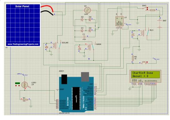
Switching section and the sensors are interfaced with a microcontroller. Here, Microcontroller is main heart of the system. The switching action between differentsourceshappentobeautomaticusingrelay,the triggered signals are sent from microcontroller. Finally, the current consumed for charging the battery. In this method we are using a current sensor ACS712 for monitoring the charging level. This system consists of current sensor, Relay and microcontroller. ACS712 is currentsensorandinourimplementationIt’sinterfaced with microcontroller. Microcontroller will read from analogpin.Oncechargingloadwillbeapproximatezero, at that time battery will be full charge. IoT is implemented by interfacing a Wi-Fi module (ESP8266), and connecting to internet. Amount generated based on the usage, which is updated on IoT and LCD. About information for charging slot available status related information will be update on Esp8266 Wi-Fi microcontroller
International Research Journal of Engineering and Technology (IRJET) e-ISSN:2395-0056
Volume: 09 Issue: 09 | Sep 2022 www.irjet.net p-ISSN:2395-0072
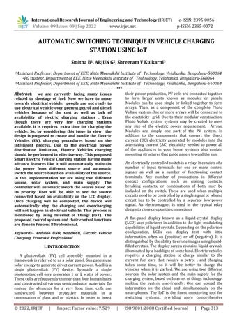
ForthisprojectsimulationtheProteus8Professional software tool is used to draw schematics, PCB layout, codeandevensimulatetheschematic.Designing,testing and debug is completely embedded inside schematic capture before making a hardware prototype. A complete workflow for designing an Arduino appliances andthencontrollingitremotelyfroma mobilephoneor browser. It was developed by Labcenter Electronic Ltd. The ATmega328P microprocessor, LDR sensors, bridge rectifier, pull down resistor, current sensor, LCD, and activeswitchwereallutilisedwiththeArduinoUno.
Proteus8ProfessionalSoftwareModules:AWindows programme for schematic capture, simulation, and PCB (Printed Circuit Board) layout design is called the Proteus Design Suite. Depending on the scale of the designs being generated and the needs for microcontroller simulation, it may be acquired in a variety of configurations. An autorouter and fundamental mixed mode SPICE simulation capabilities are included in all PCB Design solutions. A. Schematic CaptureIntheProteusDesignSuite,schematiccaptureis employed during both the design phase of a PCB layout projectandforthesimulationofdesigns.Asaresult,itis a fundamental element that comes with every product configuration. B. Microcontroller Simulation Proteus's functionsbyaddingahexfileor bydebuggingthefileto microcontrollerportionontheschematic.Theassociated analoganddigitalelectronicsarethenco-simulatedwith it. This makes it possible to utilize it for various project prototypes in fields including user interface design, temperature control, and motor control. Additionally used by general hobbyists, it is practical to use as a trainingorteachingtoolbecausenohardwareisneeded. The following are supported by co-simulation: Microchip Technologies PIC10, PIC12, PIC16, PIC18, PIC24, dsPIC33 microcontrollers Atmel AVR (and Arduino), 8051 and ARM Cortex-M3 microcontrollers ,NXP 8051, ARM7, ARM Cortex-M0 and ARM Cortex-M3 microcontrollers Texas Instruments MSP430, PICCOLO DSPandARMCortex-M3microcontrollersParallaxBasic Stamp,FreescaleHC11,8086microcontrollers
Microcontroller-ArduinoUno
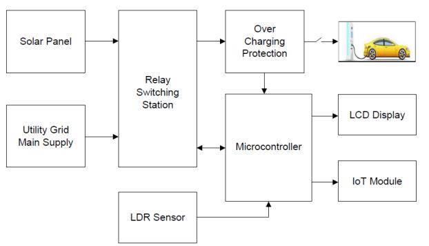
An open-source development board, Arduino Uno enables you to utilise the board to communicate with physical objects by allowing you to upload programmes to it as shown in Figure 3. It is based on the microcontroller ATMEL ATmega328p. It can interact in any way with everything that is under the influence of electricity. Additionally, it can communicate with electromagnets, sensors,andmotors. In other words, by employing this board, we may create objects that respond to the outside environment. In a nutshell, Arduino serves as the brain for countless projects. It is oneoftheArduinofamily'smoreaffordableboards.Due to its smaller size and fewer input-output pins than Arduino Mega, the bigger brother of Arduino Uno, it is commonlyutilized IoTModuleNodeMCU
Fig4:NodeMCU
International Research Journal of Engineering and Technology (IRJET) e-ISSN:2395-0056
Volume: 09 Issue: 09 | Sep 2022 www.irjet.net p-ISSN:2395-0072
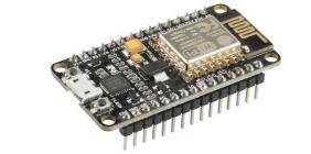
Node MCU is an open source internet of things platform .It has hardware basedontheESP-12module and an firmware that will run on Espressif Systems' ESP8266 WiFi system on chip as shown in Figure 4 Instead of the development kits, the firmware is what is typically meant by the phrase "NodeMCU." The Lua programminglanguageisemployedbythefirmware
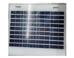
Solar panels are devices that convert the sun's energy into heat or power as shown in above Figure A solar panel really consists of a number of solar (or photovoltaic)cellsthatmayproducepowerthankstothe photovoltaic effect. On the surface of solar panels, these cellsareorganizedinagridlikeconfiguration.Asaresult, it might alternatively be defined as a collection of photovoltaicmodules putona supporting framework. A 610solarcellassemblythathasbeenpackedandlinked isknownasaphotovoltaic(PV)module
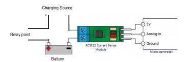
Here we connect a discharged battery or less charged batteryto this system,thechargervoltage falls toapointwherethebatteryisremoved,andthevoltage rises slowly. The battery will try to consume all the current available. The battery will consume maximum current until the terminal voltage reaches 12.4V (for a 12V battery), the voltage limited by the charger as showninaboveFigure
Fig7:FlowChart
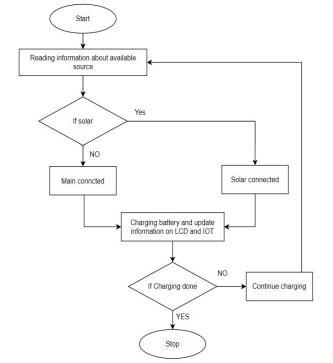
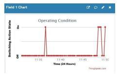
Oneofthemainsourcesofcarbondioxideemissionsand air pollution is because of the vehicles. The increase in widespread use of electric vehicles (EVs) is a potential way to tackle environmental issues and reduce carbon emissions in the transportation industry. In the project designed, we have developed a charging station for electric vehicle. We are able to successfully able to test hardware.Itisworkingasperexpectedworking.Weare abletoswitchsourceautomaticallyasshowninFigure7 AsweknowSolarelectricityisalsoexpensiveand many times variable, conventional methods of charging that ensure100%rechargeare not still possible.In the most cases full available power from the PV array will be transferred to the battery till the voltage level increases toacertainlevel,andindicating fullchargeisachieved.
e-ISSN:2395-0056
Volume: 09 Issue: 09 | Sep 2022 www.irjet.net p-ISSN:2395-0072
Utilizing overcharging protection, the charging cable will automatically unplug from the vehicle's battery, slight overcharging will reduce a cell’s discharge capacity,and will lead to over discharging, which will increase impedance and heat generation, and decreases lifetimeofcell.Otherrenewableenergysourcescanalso be used without using the utility grid, in addition to solar. This strategy decreases pollution while increasing electric vehicle EV usage, which results in a pollutionfreeenvironment.
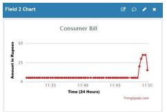
The following Figure 8 shows the consumer bill plottedagainstamountinrupeesversustimein24-hour clock.
1. Stephen Lee, Srinivasan Iyengar, David Irwin, and Prashant Shenoy, Shared Solar-powered EV Charging Stations: Feasibility and Benefits. Online Available: http://dx.doi.org/10.1109/IGCC.2016.7892600
2.Mr.C.Chellaswamy,V.Nagaraju,andR.Muthammal, Solar and Wind Energy Based Charging Station for Electric Vehicles. Online Available: https://www.irjmets.com/uploadedfiles/paper//issue _5_may_2022/22313/final/fin_irjmets1651 918827.pdf
3.DrissOulad-abbou,SaidDoubabi,andAhmedRachid, Solar Charging Station For Electric Vehicles. Online Available: https://doi.org/10.1109/IRSEC.2015.7454947
This project proposed using IoT, an Automatic Switching Technique in Electrical Vehicle Charging StationprototypeisdevelopedDuetotherestrictionson electrical power distribution. Charging of Electric Vehicles should be performed in the effective way. The proposed Smart Electric Vehicle Charging station is having many advanced features like, automatically maintaining the power from different source and automatic switching of the source based on availability of source. In this implementation we are using two different sources, suchas solar system and the main supply.Thecontrollerusedwillautomaticallyswitchthe source based on its priority. User will be able to see amountinLCDdisplay.Oncechargingwillbecompleted, the device can be stopped charging and overcharging will not happen in electrical vehicle. This prevents overheating,explodinglithiumionbatteries,longercycle life,andbatterylife.Also,usingthismethod,dependency onutilitygridcanalsobereduced.
4. Md Sohail Tanveer, Sunil Gupta, Rahul Rai, Neeraj Kumar Jha, and Dr. Mohit Bansal, Solar Based Electric Vehicle Charging Station. Online Available: https://doi.org/10.1109/PEEIC47157.2019.8976673
5. Jianmin Jia, Chenhui Liu, and TaoWan, Planning of the Charging Station for Electric Vehicles Utilizing Cellular Signaling Data. Online Available: https://doi.org/10.3390/su11030643
6. Prof.Vishal K. Vaidya, Kaiwalya S. Kulkarni, Mahesh B. Patil, Onkar V. Bhole, and Kedar P. Pathak, Solar based Electric Vehicle Smart Charging Station. Online Available: https://www.irjet.net/archives/V7/i3/IRJETV7I3232.pdf
7.KattimaniH.D,SayaleeSanjayKahandal,Mohammad Adil Ansari, Nikita Chuhan,and Rupansha Khare, Solar Powered Portable Electrical Vehicle Charging Station. Online Available: https://www.irjet.net/archives/V7/i7/IRJETV7I797.pdf
8. Mrs.R.Saranya, K.Ramya, K.Hema, and P.Pavithra, Hybrid Electric Vehicles Using Solar And Wind Energy
International Research Journal of Engineering and Technology (IRJET) e-ISSN:2395-0056
Volume: 09 Issue: 09 | Sep 2022 www.irjet.net p-ISSN:2395-0072
With Pic Microcontroller. Online Available: https://www.irjet.net/archives/V7/i9/IRJETV7I9455.pdf
9. Monik M. Dholariya, Barvaliya Aakash, Gondaliya Kenil, Pansuriya Prashant, and Dhyey R. Savaliya, A Hybrid Power Generation System by Solar Energy and Wind Energy. Online Available: https://www.irjet.net/archives/V7/i6/IRJETV7I6706.pdf
10. Dian Wang, Fabrice Locment, and Manuela Sechilariu, Modelling, Simulation, and Management Strategy of an Electric Vehicle Charging Station Based on a DC Microgrid. Online Available: https://doi.org/10.3390/app10062053
11. Vaibhav S. Bansod, Kavita G. Ghawat, Ankita R. Kadu, and P. V. Raut, Microcontroller based Automatic Power Change over Mechanism. Online Available: https://www.irjet.net/archives/V7/i2/IRJETV7I2536.pdf