International Research Journal of Engineering and Technology (IRJET) e-ISSN: 2395-0056

Volume: 09 Issue: 09 | Sep 2022 www.irjet.net p-ISSN: 2395-0072
International Research Journal of Engineering and Technology (IRJET) e-ISSN: 2395-0056
Volume: 09 Issue: 09 | Sep 2022 www.irjet.net p-ISSN: 2395-0072
Shubham R Pawar, MIT-WPU, Pune, India, Shubham H Alhat, MIT-WPU, Pune, India, Prof. Dr.D.R.Waghole, Associate Professor, MIT WPU, Pune, India, Prof. Sachin R. Deshmukh, Assistant Professor, MIT-WPU, Pune, India ***
Abstract - This project is implemented to design the possible window cleaning robot for high-rise building. The study focuses on designing a conceptual design where three main tasks being carried out. The first is to generate several design concepts based from engineering specification generated using designing and analyzing software’s. The second step involves an engineering analysis on the selected design concept such as the static frictional force, suction cup force, and motor torque required. The final step is to come out with final design using CATIA, ANSYS. Based from this, the final design of the project is designed weighted approximately of 5kg. The window cleaning robot uses 20 motors and 6 suction cups where 18 of the motor acts to drive the robot vertically (upward/downward) and the other one horizontally while the suction cups are used to grip onto the windowpane. This thesis includes background and objectives of this research, design concepts, engineering analysis, the final design, discussion and a conclusion.
Keywords – Window cleaning mechanism, Multi-utility equipment, Coefficient of Friction, Vacuum Ejectors, Gripping Systems, Torque Calculations.
Glasswindowcleaninginhighrisebuildingiscurrently having high demands in modern cities. As a result, window cleaners need to risk their life by climbing the wallusingropeandgondolatodothecleaning.Currently maximumarestillcleanedmanually.Statisticsshowsthat glass window cleaning is probably the most hazardous maintenanceactivitycarriedoutonmostworkpremises. AtUSonly,averageof70windowwashersdieeachyearin the US, while another 130 are injured. By designing a mobile machine that can do the cleaning, this will help reducingthestatistics.Whiletherearealreadynumbersof the same project outside, it is still not yet fully finished andcommercialized;thisprojectisdonetobringinnew ideasandinnovationonthewindowcleaningrobottoa new perspective. Currently, the market demands many automaticwindowscleaningsystem.Fromthesurvey,the requirementsofwindowcleaningrobotarelistedbelow:
i. The size of the robot should be small and lightweightformobilityandportability
ii. Therobotmustbeabletocleanwindow’scorner becausefoulingisleftthereoften
iii. Therobotmustbeabletosweepthewindowpane continuouslytopreventstripepatternonthewindow
iv. The robot can operate automatically during movingonthewindowThisprojectwillbasicallycoverup theserequirementswhichareelaboratedindetailsinthis thesistocomeoutwithaworkingconceptualdesign
This project will be focusing on designing a window cleaningrobots.Therobotsmustinclude4mechanisms whicharegrippingmechanism,locomotionmechanism, cleaningmechanismandturningmechanism.Tocomeout tothefinaldesign,threemainstepsneedtobecarriedout. The first part is the concepts generation where several conceptdesignsarecreatedbasedfromtheengineering specifications that are derived from customer’s requirements.Thesecondpartistheengineeringanalysis. Basedonthebestconceptchoseintheprevioussection, an analysis done to calculate the static frictional force involve in the robot system, the suction cup calculation and selection and the motor torque calculation and selection.And base fromthefirstandsecond part, final conceptualdesignisdrawninCATIA,ANSYS,etcbefore thefabricationcanbestarted.
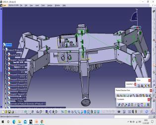
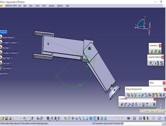
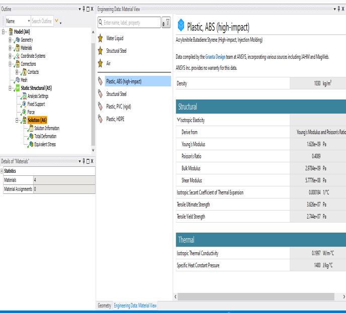
The CAD design of the platform was done on CATIA SoftwareandtheStructural Analysiswasperformedon AnsysSoftware.ThegeometrygeneratedonCATIAwas importedinAnsysandameshwasgenerated.Themesh generatedwasautomatictypewithaveryhighresolution. TheMaterial selectedfor the body isABS(Acrylonitrile ButadieneStyrene).
• Objectiveistofindoutthetorquesactingateachdegree offreedomofa6-leggedrobot.
• Inordertoobtainaproperbalanceduring themotion therobotmustbestaticallysable.
• Inthecaseofahexapod,solongas3legsarealwaysin contact with the ground and the center of mass is locatedwithinthetriangleformedbythesefeet,itwill bestaticallytable.
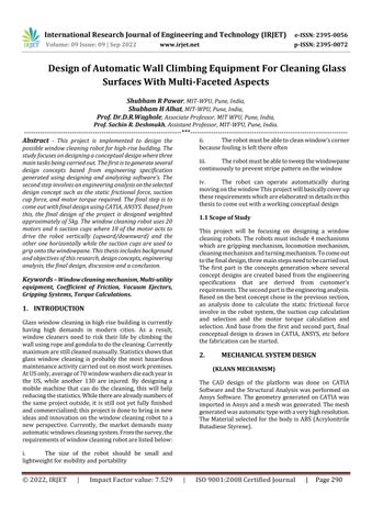
• Theconditionisshown inthefigure:- N isthenormal force
• N1,2:normal(reaction)force.
• L1,2,3:lengthofthelink.
• W1,2,3:weightofeachactuator(W2,3areassumedto beveryclose).
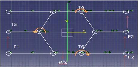
• W4:Weightactingatthecenterofmass.
• T1,2,3,4: Torque acting at each joint (each side is different)
• InordertodeterminethetorqueT1actingatthe"knee", we must assume that the rest of the structure is rigid (notmoving).
• Similarly,whenfindingT2,actingatthe"hip"therestof the structure (including the torque T1) is considered rigid.
• Thelinksareconsideredtobemassless.
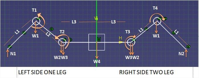
• Thelinksthatmakeupan“insect”legdonotnecessarily need to be perpendicular to one another, as shown in theimagebelow:-
• ThetorquesT3andT4willbedifferentthanT1andT2 because the central weight is not being supported equallyamongthethreelegs.
• Inthiscase,T1>T4andT2>T3,sowewillonlycalculate T1andT2
• TheweightW4actingatthecenteroftherobotwhen3 legsareraisedisacombinationofvariouspartsbelow:W4 = WFrame + WElect + WBattery + W3 + Legs
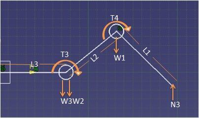
• Theanglesaretakenbetweenthehorizontalandthelink anditisassumedthelegs areconfiguredthesame on bothsides.
• Thefollowingassumptionsmustalsobemadeinorder tosimplifythecalculationsandinputsrequired:
6legs,configuredastworowsof3.
Allthelegsareidentical.
• In order to find the torque acting at each joint, a free bodydiagrammustbedrawn.
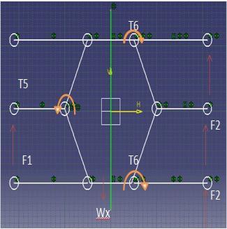
• Allsupportinglegsmustbeconsidered:-
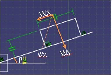
• Thereactionforcescounteracttheweightoftherobot which would otherwise cause it to slide down the incline.
• Themagnitudeoftheweightofgravityalongtheslope canbecalculatedas:-
International Research Journal of Engineering and Technology (IRJET) e-ISSN: 2395-0056
Volume: 09 Issue: 09 | Sep 2022 www.irjet.net p-ISSN: 2395-0072
• Atorquebalanceabouttheleftshoulderactuatorgives:1 – F1 * (L1 * Cosθ1 + L2 * Cosθ2) – L3 * Wx + 2 * F2 * (2 * L3 + L1 * Cosθ1 + L2 * Cosθ2)
• Inordertomovestraight,theforceontheleftsidemust equal the force on the right side, otherwise the robot wouldbegintoturn. So, F1=2*F2
• Thetorquesaboverepresenttherequiredtokeepthe robotstationaryanddoesnotincludetheextratorque requiredformotion.
• Forselectionofmotorwemustadd25%toeachtorque asafactorofsafety.
• CalculationoftherequiredsuctionrateV[M3/H,L/Min].
• V=nxVS
1. n=numberofsuctionpads.
2. VS=requiredsuctionrateforsinglesuctionpad [m3/h,I/min].
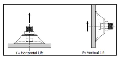
Toachieveagoodadhesion,thesuctioncupneedtohave highgrippingforceandatthesametimenottoohighsothat wecanreducethetorqueandforceofthemotorsthatmove thewheels.Forforwardmovement,therobotwilluselinear actuatorandtheactuatorneedstohaveacapacitytopush or pull the robot weight. Thus, the calculation is done to ensuretherightchoiceofsuction cupandmotorsforthe robotgrippingandlocomotionmechanism.
ApplyNewtonLawtocalculatetheforceona5kgrobot masswithachangeinaccelerationof2m/s2 andasafety factor,Svof4.
Fv (N) = mass (kg) x (ag+ a) x Sv
Fv (N) = 5kg x (9.81m/sec2 + 2m/sec2) x 4
Fv = 236.2 N
Calculate the force on a 5kg mass with a dry surface, a changeinaccelerationof2m/sec2,andachangeintravel accelerationof2m/sec2
Fm (N) = Fm (N) = = Fm = 124.69N
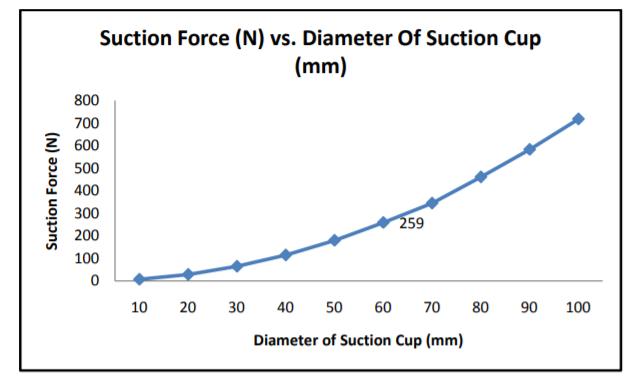
At 90% of full vacuum and 6 cups working together,
TheforcevalueiscomparedintheTable.Byapplyinga safetyfactorof2, it is recommended toselect a suction cupwithdiameterof50mmwiththeoreticalliftingforce of 259N. From chart, we can then plot a graph of the suction force (N) vs. diameter of suction cup at 90% of operatingvacuumpressureinFigure.
ApplyNewtonLawtocalculatetheforceona5kgrobot masswithachangeinaccelerationof2m/s2anda safetyfactor,SHof2.
FH (N) = mass (kg) x (ag+ a) x SH
FH (N) = 5kg x (9.81m/sec2 + 2m/sec2) x 2
FH = 118.1 N
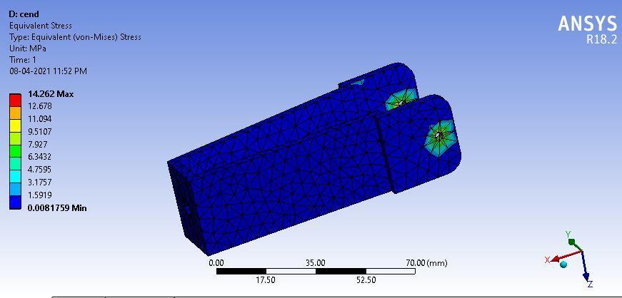
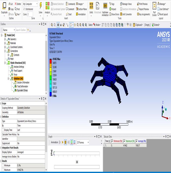
To check whether the selected material and design are safe, structural analysis was performed using Ansys software.The figures below show the Ansys results for StructuralAnalysis.
The results found out after the analysis are tabulated below.
TheAnsysresultsofthePlatform.
Leg-14.262MPa
Equivalent Stress
Plate–7.1725MPa Clamp–13.981MPa CClamp–6.4287MPa Assembly–0.04146MPa
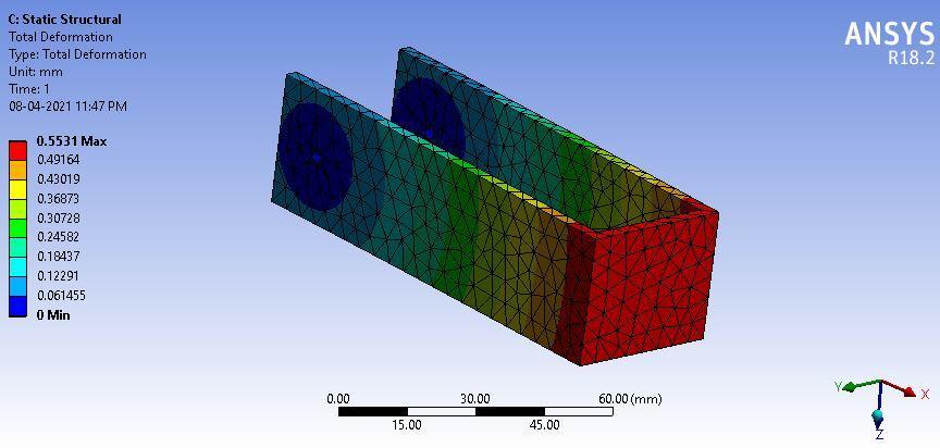
Total Deformation
Clamp-0.5531mm CClamp–0.371mm
Leg–0.60009mm Plate–3.3141mm Assembly–0.4562mm
AnsysresultforTotalDeformation
Factor of Safety (FoS)
Plate–15 CClamp–15 Clamp–15 Leg-15
International Research Journal of Engineering and Technology (IRJET) e-ISSN: 2395-0056
Volume: 09 Issue: 09 | Sep 2022 www.irjet.net p-ISSN: 2395-0072
Thecircuitdesignwhichisrequiredfortheworkingofthe robot is designed and checked on the software called Proteus. In the above figure the connections between motorsandArduinotooperatealternatelyisdefined.
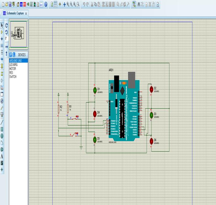
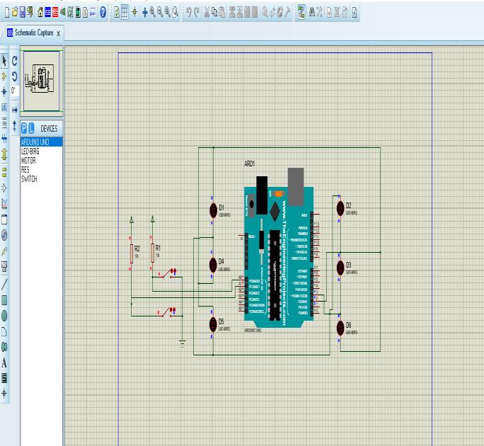
motorsandothercomponentsaccuratelyasperthe designedcodes.
Withlittleornomodification,theclimbingrobotcan be used for the following applications and also its advantagesarementioned-
• Ithasthepotentialtoserveasabaseonwhichto mount data acquisition devices, surveillance equipment,orobject-manipulationtools
• Wireless/wiredvideosurveillancecanbepossible. Publicsafety&militaryapplications(surveillance, search&rescue).
• Consumer applications (window cleaning and painting) Inspections(building,aircraft&bridges, Pipes)etc.
• Wall/glass cleaning and water sprinklers can be mounted.
• On board vacuum cylinders are not used, which increasespayloadcapacity.
1. T. Yano, S. Tomahiro, M. Murakami, T. Yamamoto, “Developmentofsemi-selfcontainedwallclimbing robotwithscanningtypesuctioncups”,Proceedings IROS97,1997,pp.900-905
2. SuryakantRathod,AnkurRai,ChandanKumar,Raj Kumar. Skyscrapers Wall Climbing and Glass CleaningAutomatedRobot.2017IJSRSET,Volume3, Issue3,PrintISSN:2395-1990,OnlineISSN:23944099.
Simulationofthecircuit.
• Desiredcalculationforrobothaveobtained.
• Therobotissmallandcompact.
• Thedesignedmechanismisfavorableofrobot.
• TheMaterialselectedforthedesignislightinweight andcanwithstandinrequiredconditions.
• Thecomponentsselectedfortherobotarecheapand easytoavailable.
• Successful simulation of circuit is obtained on Proteus. The circuit represents the working of
3. M. Rafeeq, S. F. Toha, S. Ahmad, M. S. M. Yusof, M. A. M. Razib and M. I. H. S. Bahrin, "Design and Modeling of Klann Mechanism-Based Paired Four LeggedAmphibiousRobot,"in IEEE Access,vol.9,pp. 166436-166445, 2021, doi: 10.1109/ACCESS.2021.3135706.
4. “SIX LEGGED SIDER ROBOT USING KLANN MECHANISM”, International Journal of Emerging Technologies and Innovative Research (www.jetir.org|UGCandissnApproved),ISSN:23495162,Vol.6,Issue5,May2019
5. K.A. Daltorio, S. Gorb, A. Peressadko, A.D. Horchler,R.E.Ritzmann,andR.D.Quinn,ARobotthat ClimbsWallsusingMicro-structuredPolymerFeet, Proc. International Conference on Climbing and WalkingRobots,London,UK,2005.