e-ISSN:2395-0056
Volume: 09 Issue: 09 | Sep 2022 www.irjet.net p-ISSN:2395-0072

e-ISSN:2395-0056
Volume: 09 Issue: 09 | Sep 2022 www.irjet.net p-ISSN:2395-0072
1,2,3,4,5UG-scholar, department of mechanical engineering, JSS Academy of Technical Education, Noida, India 6Assistant professor department of mechanical engineering, JSS Academy of Technical Education, Noida, India ***
Abstract - This review paper comprises the use of phase change materials (PCMs) in various types of heating/cooling systems as an effective means of blocking energyand maintainingtemperatureswithinthe well-being zone.PCMshavebeenwidelyusedinavarietyofsystemsfor heat pumps, solar engineering, and thermal control. During the last decade, researchers have looked at the usage of PCMs in heating and cooling applications. PCMs are abundant and melt and solidify at a wide range of temperatures, making them useful in a variety of applications. This study also discusses the investigation and analysis of Phase Change materials utilised in various heating/coolingsystemsandtheirapplications.
Key Words: PCMs, ANSYS, Meshing, Thermal Energy Storage Analysis, house cooling
Due to rising global energy consumption associated with thegrowthofcivilizationandtheconcomitantdepletionof conventional energy sources, several countries are implementing technological solutions to minimise energy consumption in different areas, including construction. Scientific research is currently being conducted in a numberofresearchinstitutesacrosstheworldinorderto develop material and technology solutions that will allow rooms to maintain adequate thermal comfort throughout periods of low or high outside air temperatures. Simultaneously, solutions related to the possibilities of employing energy from renewable sources, including in the case of building partitions, thermal energy from solar energy conversion, are being researched. To increase thermalcomfortinbuildingrooms,phasechangematerial isincreasinglybeingemployed,whichlowerstemperature changes on the interior surface of the partition due to its heat storage capabilities. This material is used to reduce the amount of energy required to cool or heat rooms in a buildingbyincorporatingitintopassiveoractivesystems. In passive systems, phase change material (PCM) is used in many construction components. The goal of this approach is to collect thermal energy from a variety of sources and then direct that energy toward Lower temperatures. Wall partitions are commonly utilised
regardless of the building's structural architecture, although they can also be found in floors and roof elements. The application procedure for phase change materials is determined by the type of PCM and its location.It'smostcommonlyusedinmicrocapsuleformin concrete elements. PCM is added to the concrete mix, which is then used to make concrete wall elements, and the samples were utilised to determine the thermal properties of composites. Varied computational methods wereusedtocharacterisetheheatflowthroughthetested materials with various concentrations of PCM in the sampleandheatcapacity.
Phase change material is used in a variety of building items, including ceramic components. Filling existing gaps in finished masonry using phase change materialisoneoftheoptionsformodifyingthesefeatures. A separate PCM layer on the inside or outside of the ceramic partition, or between the partition layers, is another option. Modification of phase change material for items used as indoor interior cladding is also being researched. The goal of this alteration is to absorb excess thermal energy inside the space, which can come from a variety of sources, including solar radiation coming through the building's major glazed surfaces or the operation of electronics inside the room. Research confirmsthe beneficial effectof phase change material on thestabilisationoftemperaturesontheinternalsurfaceof thepartition,regardlessofthelocationofthePCMandthe partitionstructureinwhichitwasused,duringperiodsof significant temperature fluctuations and room overheating.
There is an issue with the basic thermal parameters for these composites when developing customised parts or multilayer construction partitions. We frequently receive fundamental physical and mechanical attributes for prefabricated pieces prepared by the manufacturer (parameters). Obtaining thermal parameters needs the use of available research methods, such as experimental, computational, or computer simulations, despite the fact that the element or partition is made up of numerous materials. In many research facilities, studies are conducted using a single method or a combination of
International Research Journal of Engineering and Technology (IRJET) e-ISSN:2395-0056
Volume: 09 Issue: 09 | Sep 2022 www.irjet.net p-ISSN:2395-0072
methodologies, with the results compared. Experiments on a single building component or a modified multilayer building partition can be carried out using the experimentalapproach.
These studies are conducted in a laboratory setting or in (outside) field settings under natural climate conditions. The authors of the research conducted tests in a laboratorychamberonaPCMmodifiedwalltoinvestigate the effect of temperatures on the effective thermal conductivity of this partition. These experiments were conducted in a constant state, demonstrating a good link between thermal conductivity and growing temperature. Thermalcharacteristicsofbuildingcomponentswerealso studied in the next papers. Available statistical programmes can also be used to analyse the results of laboratory tests. More information regarding the physical and mechanical properties of newly built composites or redesigned building partitionscan begathered asa result ofsuchstudy.
A phase change material (PCM) is a substance that releases/absorbs enough energy to generate useful heat/cooling at phase transition. In most cases, the transition will be between one of the first two fundamental states of matter, solid and liquid. The phase transition may also occur between non-classical states of matter,suchascrystalconformance,inwhichthematerial transitions from one crystalline structure to another, whichmayhaveahigherorlowerenergystate.
For the analysis, a model with a base dimension of 7.31m*7.31m*0.005 mand a surface area of 53.43m2 was used. On this foundation, a room model with four walls, one roof, twoglasswindows,and onedoor was built. The room'sdimensionswere5.18m*4.87m*5.18m,resultingin avolumeof31.856m3.Themodelwasthenexaminedafter various PCMs were applied to the inside surfaces of the walls.
Five variants of the PCM models were used for the purposeoftheresearch.
● Variant1(V1)-noPCM
● Variant 2(V2) - PCM used is Sodium Metasilicate Pentahydrate.
● Variant3(V3)-PCMusedisn-Hexadecane.
● Variant4(V4)-PCMusedissaveOM65.
● Variant5(V5)-PCMusedisA70PlusICE.
Becauseoftheongoingresearchusingamodifiedmasonry element in collector and accumulation walls, the aforementioned PCM layer system was postulated. The phase change material's position on the inside will block solar radiation from entering the living space, preventing energyfrombeingusedincooling.
The phase change material should possess the following thermodynamicproperties:
• Melting temperature in the desired operating temperaturerange
• Highlatentheatoffusionperunitvolume
• High specific heat, high density, and high thermal conductivity
• Chemicalproperties
• Chemicalstability
• Completereversiblefreeze/meltcycle
• No degradation after a large number of freeze/meltcycle
• Non-corrosiveness, non-toxic,non-flammable and non-explosivematerials
• Economicproperties
• Lowcost
• Availability
Since PCMs transform between solid–liquid in thermal cycling, encapsulation naturally became the obvious storage choice. Following are some of the encapsulation techniquethatareusedfortheencapsulationofPCMs-
● Macro-encapsulation
● Micro-encapsulation
● Molecular-encapsulation
Inthistechnique,PCMhastobeencapsulatedbeforebeing used into construction elements. Here, the microencapsulation is summarised. The process that PCM particles are contained in a thin and stable shell (ranging from 1 -m to 1000 -m) is known as microencapsulation.
2022, IRJET | Impact Factor value: 7.529 | ISO 9001:2008 Certified Journal | Page 276
International Research Journal of Engineering and Technology (IRJET) e-ISSN:2395-0056
DuetotheseadvantagesofpreventingtheleakageofPCM andhighheat-conductionability.Therefore,itschancesof beingincorporatedintovariousconstructionmaterialsare increasedgreatly.
The Project is completed with the encapsulation of different phase change materials placed in the walls. The setupismadewithfewerjointstodecreasethewastage.
Many decisions need to be made in order to produce the mostdesirableandaffordableproducttomakethehighest profit and most unique devices. There are three distinct phases: The concept phase, the study phase, and the production phase. During the concept phase, we defined theproblemofstoringthermalenergyforalongduration. We then conceptualised in different ways by cascading of PCMsindifferentlayersbyusingdifferenttypesofPCMs.
Through research and customer surveys, we entered the studyphaseknowingconsumerpreferences.
After reviewing our results, we hypothesised how we would enter the production phase. Because this product wouldbeproducedinbulk,wetookintoaccounttheprice ofmachinery,storage,labour,etc.
After all of those costs were accounted for, we analysed potentialifthetaskcouldbeachievedpractically.
Steady-state thermal analysis is evaluating the thermal equilibriumofasysteminwhichthetemperatureremains constant over time. In other words, steady-state thermal analysis involves assessing the equilibrium state of a system subject to constant heat loads and environmental conditions. The simplest form of steady-state analysis is linear steady-state analysis in which input parameters, such as material properties, are prescribed independent variables.
The following figure shows the steady state thermal analysissetup.Wehavecreated2modelswhichare-
• NonPCMbasedmodel
• PCM based model consisting of different PCM materialanalysis
Followingphysicalspecificationswereconsideredforthe purposeoftheanalysis-
• LengthOfRoom=5m
• BreadthOfRoom=5m
• HeightOfRoom=5m
• AreaOfPlot=7.31m*7.31m=53.43m2
Thefollowingmaterialswereconsideredduringanalysis–
• Concrete
• OakWood
• Glass
• Wood
• Sodium Metasilicate Pentahydrate (Thermal Conductivity–0.1W/m.oC)
• N-hexadecane (Thermal Conductivity – 0.154 W/m.oC)
• Save Om 65 (Thermal Conductivity – 0.19 W/m oC)
• A70 Plus ICE (Thermal Conductivity – 0.23 W/m oC)
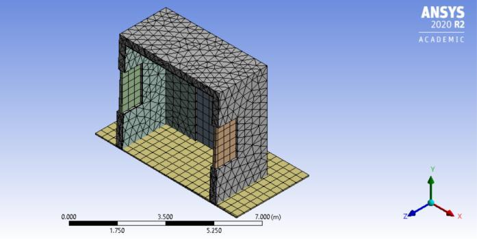
A mesh is a representation of a larger geometric domain by smaller discrete cells. Meshes are commonly used to compute solutions of partial differential equations and render computer graphics, and to analyse geographical and cartographic data. A mesh partitions space into elements(orcellsorzones)overwhichtheequationscan be solved, which then approximates the solution over the largerdomain.Elementboundariesmaybeconstrainedto lie on internal or external boundaries within a model. Higher-quality (better-shaped) elements have better numerical properties, where what constitutes a "better" element depends on the general governing equations and the particular solution to the model instance. A mesh is considered to have higher quality if a more accurate solutioniscalculatedmorequickly.
Table4.3.1Meshingdetailsofthemodel
Properties Values
ElementSize 0.33m
ElementOrder Linear
NumberofNodes 5266
NumberofElements 13835 Smoothing Medium
Volume: 09 Issue: 09 | Sep 2022 www.irjet.net p-ISSN:2395-0072 © 2022, IRJET | Impact Factor value: 7.529 | ISO 9001:2008 Certified Journal | Page 277
International Research Journal of Engineering and Technology (IRJET) e-ISSN:2395-0056
Volume: 09 Issue: 09 | Sep 2022 www.irjet.net p-ISSN:2395-0072
• MinimumTemperature-34.649 oC
• AverageTemperature-38.566 oC
Fig.4.3.1MeshingOfthemodel
The Project is completed with the encapsulation of different phase change materials placed in the walls. The setup is made with fewer joints to decrease the wastage. Four types of PCMs are placed in the walls. The temperature of the room from inside increases as the thermalconductivityofthePCMisincreased.
Temperatureincreasessharplyuntilitreachesthemelting zoneofrespectivePCMs.
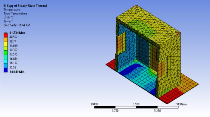
5.1 Wall without PCM
Temperaturesfromtheanalysisshowsfollowingresult-
• MaximumTemperature-39.991 oC
• MinimumTemperature-37.132 oC
• AverageTemperature-38.531oC
Fig5.1VariationofTemperatureintheRoomwithoutUse ofPCM
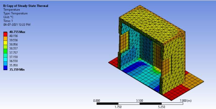
5.2 Wall with PCM used is Sodium Metasilicate Pentahydrate
Temperaturesfromtheanalysisshowsfollowingresult-
• MaximumTemperature-41.234 oC
Fig5.2VariationofTemperatureintheRoomwithuseof SodiumMetasilicatePentahydrate
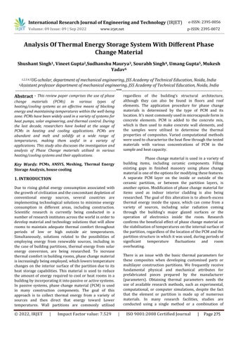
5.3 Wall with PCM used is n-Hexadecane
Temperaturesfromtheanalysisshowsfollowingresult-
• MaximumTemperature-40.755 oC
• MinimumTemperature-35.359 oC
• AverageTemperature-38.692oC
Fig5.3VariationofTemperatureintheRoomwithuseof n-hexadecane
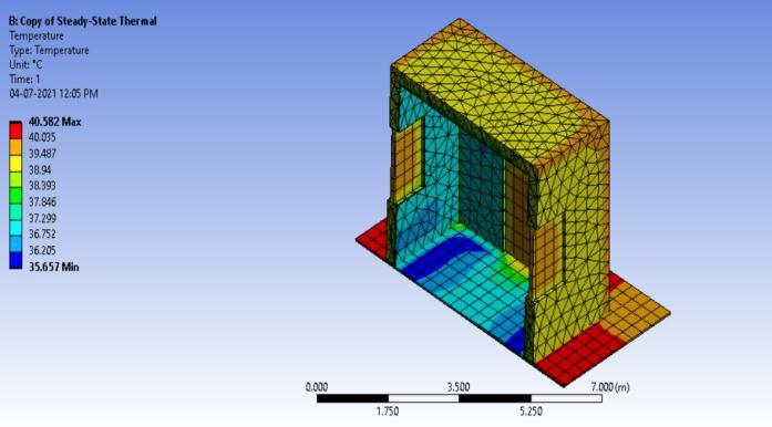
5.4 Wall with PCM used is savE OM 65
Temperaturesfromtheanalysisshowsfollowingresult-
• MaximumTemperature-40.582 oC
• MinimumTemperature-35.657 oC
• AverageTemperature-38.736 oC
•
International Research Journal of Engineering and Technology (IRJET) e-ISSN:2395-0056
Volume: 09 Issue: 09 | Sep 2022 www.irjet.net p-ISSN:2395-0072
Maximum Temperat ure (Outside wall)
Minimum Temperat ure (Inside Wall)
39.9 9 oC 41.234 oC 40.755 oC 40.58 2 oC 40.43 oC
37.1 3 oC 34.649 oC 35.359 oC 35.65 7 oC 35.90 oC
Withtheconclusionoftheanalysis,theprojectcomestoa close.Thetestresultsarelistedinthetablesabove.
• The test was conducted to confirm that PCM may be used in our construction process to lower the amount of energy required to cool/warm the room to a human comfortabletemperature.
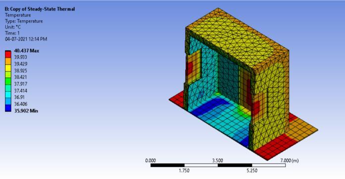
• MinimumTemperature-35.902 oC
•
• UsingthevariousPCMs,itcanbeseenthatasthe Thermal Conductivity of PCMs increases, so does the temperatureinsidetheroom.
• As a result, a PCM with poor heat conductivity should not be employed to get the most out of this approach.
• If we use a Sodium Metasilicate Pentahydrate (Thermal Conductivity – 0.1 W/m .oC) the minimum temperaturedroppedfrom37.132 oCto34.649 oCwhichis a8%dropintemperature.
• Ifweusean-Hexadecane(ThermalConductivity–0.154 W/m .oC) the minimum temperature dropped from 37.132 oCto35.359 oCwhichisa5%dropintemperature.
• If we use a SavE OM65 (Thermal Conductivity –0.19 W/m .oC) the minimum temperature dropped from 37.132 oC to 35.657 oC which is a 4.1 % drop in temperature.
• IfweuseanA70PlusICE(ThermalConductivity –0.23 W/m .oC) the minimum temperature dropped from 37.132 oC to 35.902 oC which is a 3.4 % drop in temperature.
[1] Al-Jethelah, M., Tasnim, S. H., Mahmud, S., & Dutta, A. (2018).“Nano-PCM filledenergystoragesystemforsolarthermal applications”, Renewable energy, pp. 126, 137155.
[2] Lichołai, L.; D˛ebska, B.; Kraso´ n, J. (2019). “Assessment of the applicability of a phase change material in horizontal building partitions.” IOP Conf. Ser. EarthEnviron.Sci.,pp.214,012042
[3]Castell,A.;Martorell,I.;Medrano,M.;Perez,G.; Cabeza, L.F. (2010) “Experimental study of using PCM in brick constructive solutions for passive cooling.” Energy Build. pp.42,534–540.
[4] Gulfam, R., Zhang, P., & Meng, Z. (2019). “Advanced thermal systems driven by paraffin-based phase change materials–Areview”.Appliedenergy,pp.238,582-611.
[5] Mahfuz, M., Anisur, M., Kibria, M., Saidur, R., & Metselaar, I. (2014). “Performance investigation of thermal energy storage system with Phase Change Material (PCM) for solar water heating application. InternationalCommunicationsinHeatandMassTransfer”, pp.57,132-139.
[6] Wang, X.; Yu, H.; Li, L.; Zhao M. (2016) . “Research on temperature dependent effective thermal conductivity of composite-phase change materials (PCMs) wall based on steady-statemethod ina thermal chamber.” EnergyBuild, pp.126,408–414.
[7] Li, L.; Yu, H.; Liu, R. (2017). “Research on compositephase change materials (PCMs)-bricks in the west wall of room-scale cubicle: Mid-season and summer day cases.” pp.123,494–503.
[8] Xie, J.;Wang,W.; Sang, P.; Liu, J. (2018). “Experimental and numerical study of thermal performance of the PCM wallwithsolarradiation.”pp.177,443–456.
[9]Joanna Krason , Przemysław Miasik , Lech Lichołai , Bernardeta D ebska & Aleksander Starakiewicz (2016). “Analysis of the Thermal Characteristics of a Composite Ceramic Product Filled with Phase Change Material”. Buildings,pp.9,217.
[10]Elarga,H.,Fantucci,S., Serra,V.,Zecchin,R.,&Benini, E. (2017). “Experimental and numerical analyses on thermal performance of different typologies of PCMs integrated In the roof space.”. Energy and Buildings, pp.150,546-557.
[11]LuisaF.Cabezaa,CeciliaCastellona,MiquelNogues, Marc Medranoa , Ron Leppers , Oihana Zubillaga (2006). “Use of microencapsulated PCM in concrete walls for energysavings”EnergyandBuildings,pp39,113–119.
[12] Heim, D. (2010) “Isothermal storage of solar energy inbuildingconstruction”.RenewEnergy,35,788–796
International Research Journal of Engineering and Technology (IRJET) e-ISSN:2395-0056 Volume: 09 Issue: 09 | Sep 2022 www.irjet.net p-ISSN:2395-0072 © 2022, IRJET | Impact Factor value: 7.529 | ISO 9001:2008 Certified Journal | Page 280
[13]Mehdaoui,F.;Hazami,M.;Messaouda,A.;Taghouti,H.; Guizania, A. (2019) , “Thermal testing and numerical simulation of PCM wall integrated inside a test cell on a smallscaleandsubjectedtothethermalstresses.” Renew. Energy,pp.135,597–607.
[14] Xie, J.;Wang,W.; Sang, P.; Liu, J.(2018). “Experimental and numerical study of thermal performance of the PCM wall with solar radiation.” Constr. Build. Mater., pp. 177, 443–456.
[15] Kośny, J. (2015). “PCM-enhanced building components: an application of phase change materials in building envelopes and internal structures”, pp. 19, 788794.
[16] Mahfuz, M., Anisur, M., Kibria, M., Saidur, R., & Metselaar, I. (2014). “Performance investigation of thermal energy storage system with Phase Change Material (PCM) for solar water heating application.” International Communicationsin Heat andMassTransfer, pp.57,132-139.
[17] Safari, A., Saidur, R., Sulaiman, F., Xu, Y., & Dong, J. (2017). “A review on supercooling of Phase Change Materials in thermal energy storage systems.” Renewable andSustainableEnergyReviews,pp.70,905-919.
[18] Khudhair A.M., Farid M.M. (2004). “A review on energyconservationinbuildingapplicationswiththermal storage by latent heat using phase change materials.” EnergyConversionandManagement,p.263-275.
[19] Zalba B., Marın J.M., Cabeza L.F., Mehling H. (2003). “Review on thermal energy storage with phase change: materials,heattransferanalysisandapplications”,Applied ThermalEngineering,p.251–283.
[20] Karthikeyan S.,Muthu Saravanan S., Prashanth R. (2006), “Energy conservation through phase change material based thermal energy storage system-a project report”,AnnaUniversityChennai.
[21]A. Abhat (1983), “Low temperature latent heat thermal energy storage: heat storage materials”, Sol. Energy,pp.313–332.
[22]K. Kaygusuz (1999), “The viability of thermal energy storage”,pp.745–755.
[23]A. Sharma, V.V. Tyagi, C.R. Chen, D. Buddhi (2009), “Review on thermal energy storage with phase change materialsandapplications”,pp.318–345.
[24]H. Singh, R.P. Saini, J.S. Saini (2010), “A review on packedbedsolarenergystoragesystems”,pp.1059–1069.
International Research Journal of Engineering and Technology (IRJET) e-ISSN:2395-0056
Volume: 09 Issue: 09 | Sep 2022 www.irjet.net p-ISSN:2395-0072
[25]T.E. Alam, J. Dhau, D.Y. Goswami, M.M. Rahman, E. Stefankos(2014),“Experimentalinvestigationofapackedbedlatentheatthermalstoragesystemwithencapsulated phasechangematerial”.
[26]A.S. Fleischer (2015), “Thermal Energy Storage Using PhaseChangeMaterials”,pp.7–36.
[27]B. Zalba, J.M. Marin, L.F. Cabeza, H. Mehling (2003), “Review on thermal energy storage with phase change : materials,heattransferanalysisandapplications”
[28]T.K. Aldoss, M.M. Rahman (2014), “Comparison between the single-PCM and multi-PCM thermal energy storagedesign”,pp.79–87.
[29]F. Agyenim, N. Hewitt, P. Eames, M. Smyth (2010), “A review of materials, heat transfer and phase change problem formulation for latent heat thermal energy storagesystems”, pp.615–628.
[30]M. Iten, S. Liu (2014), “A work procedure of utilising PCMs as thermal storage systems based on air-TES systems”,pp.608–627.
[31]P. Tatsidjodoung, N. Le Pierrès, L. Luo (2013), “A reviewofpotentialmaterialsforthermalenergystoragein buildingapplications”,pp.327–349.
[32]M.K.A. Sharif, A.A. Al-Abidi, S. Mat, K. Sopian, M.H. Ruslan,M.Y.Sulaiman, M.A.M. Rosli (2015), “Review of the application of phase change material for heating and domestic hot water systems”,pp.557–568.
[33]M.M. Farid, A.M. Khudhair, S.A.K. Razack, S. Al-Hallaj (2004), “A review on phase change energy storage: materialsandapplications”,pp.1597–1615.
[34]A.I.N. Korti, F.Z. Tlemsani (2016), “Experimental investigationoflatentheatstorageinacoilinPCMstorage unit”,pp.177–186.
[1] P. Tatsidjodoung, N. Le Pierrès, L. Luo (2013), “A reviewofpotentialmaterialsforthermalenergystoragein buildingapplications”,pp.327–349.
[2] M.K.A. Sharif, A.A. Al-Abidi, S. Mat, K. Sopian, M.H. Ruslan,M.Y.Sulaiman, 47 M.A.M.Rosli(2015), “Review of the application of phase change material for heating and domestichotwatersystems”,pp.557–568.
[3] M.M. Farid, A.M. Khudhair, S.A.K. Razack, S. Al-Hallaj (2004), “A review on phase change energy storage: materialsandapplications”,pp.1597–1615.
[4] A.I.N. Korti, F.Z. Tlemsani (2016), “Experimental investigationoflatentheatstorageinacoilinPCMstorage unit”,pp.177–186.
2022, IRJET | Impact Factor value: 7.529 | ISO 9001:2008 Certified Journal | Page 281