International Research Journal of Engineering and Technology (IRJET) e-ISSN: 2395-0056

Volume: 09 Issue: 09 | Sep 2022 www.irjet.net p-ISSN: 2395-0072
International Research Journal of Engineering and Technology (IRJET) e-ISSN: 2395-0056
Volume: 09 Issue: 09 | Sep 2022 www.irjet.net p-ISSN: 2395-0072
1,2,3,4 B.Tech Student, Department of Mechanical Engineering, Rajadhani Institute of Engineering and Technology, Trivandrum, Kerala 695102 ***
Abstract - The purpose of this thesis is to design and create a chassis frame for a harvesting automobile's harvesting mechanism. The focus of this research is on the viability of simple manufacturing at the lowest possible cost. The present industries have identified many types of chassis for forming equipment, particularly harvesting equipment. Those chassis are being investigated. Different harvesting equipment load scenarios are also investigated. A new chassis design is created based on the findings of the investigation using Solidworks 2020. The harvesting part assemblies that were previously designed are assembled on the chassis using various bolts and plate connections to connect the various assembly parts. As previously stated, the Chassis is designed, developed, and verified for a variety of load scenarios using Ansys Workbench.
Key Words: Chassis frame, Harvesting Automobile, Harvesting Mechanism, Solidworks, Assembly, Ansys, Load Scenarios.
Farming is one of the most important occupations for generatingfoodandfoodproductsallovertheworld.Indiais one of the world's largest producers of rice, wheat, and vegetables.Farmerscultivatecropsinasystematicmanner atvarioustimesthroughouttheyear.Everycropproduction requires a great deal of manual labor and physical effort. Engineersareworkingonavarietyofsemi-automatedand mechanicalmachinerytoaidinthegrowingofformals.We aredevelopingachassisframeforatinyharvestingmachine inthisthesis.
Everyautomobile'schassisframeisacriticalcomponent.It's the foundation on which the vehicle's components are mounted. The vehicle's body is constructed on top of the chassis frame. When compared to a standard automobile chassis,thechassisframeofaharvestingmachinecarriesa varietyofloads.
Avehiclechassisisdesignedandengineered towithstand loadsresultingfromvariousflatroadconditions.However, harvestingmachinesworkinfieldswithextremelyuneven topography, putting extraordinary pressures on their chassis.
Achassisincommonbearsallofthemechanicalpartsand thevehiclebody,ensuringthatthevehicleisbalancedonthe
roadorterrain.Achassisstructurefortheaforementioned microharvesterisdesignedinthisbachelorthesis.Theloads and load cases for the chassis to function is analyzed and verifiedforitsdurability.
ChassisisaFrenchwordthatreferstothevehicle'sframe componentsorprimarystructure.Itisoftenreferredtoasa carrying unit. A chassis is the framework upon which a vehicle is constructed. It also supports numerous componentsthatareinstalledonitwhilecarryingtheweight aswellaspermitssmoothrunovervaryingroadsurface.Itis comprisedofsteelandservesasthevehicle'sbackbone.All majorunitsrequiredtodrivethevehicle,giveitmotion,and stopitisequippedonthechassisitself.
ThefollowingarethefunctionsoftheChassis.It:
Supportsorbearsthevehicle'sbodyload.
Provide space and a mounting position for various vehiclecomponents.
Supportstheweightofthevehicle'sdifferentsystems, suchastheengineandtransmission.
Supports the weight of passenger and such varying loads.
Withstandsthestrainscausedbypoorroadconditions.
Sustains vehicle stresses during braking and acceleration.
Theloadsoperatingonthechassisframeareasfollows:
Stationary loads refer to loads that are permanently attachedtothevehicle,suchasthechassisandbody.
Loadscausedby unexpectedevents,suchashead-on collisions
Loads resulting from vehicle irregularities and overloading.
Short-durationloads:thevehicleloadwhenturningor braking.
Momentary loads, which are applied to the vehicle duringrapidacceleration,sharpbraking,andsoon.
International Research Journal of Engineering and Technology (IRJET) e-ISSN: 2395-0056
Volume: 09 Issue: 09 | Sep 2022 www.irjet.net p-ISSN: 2395-0072
The weights applied when crossing terrains with irregularorunevensurfaces.
Chassisframesareclassifiedinto:
ConventionalChassisorframe-fullchassis
This type of chassis comprises of two long members and suitable number of cross members to make a ladderform.Itisusuallyseenincommercialvehicles such as trucks and busses and some SUVs. Some passengervehiclesstill use thisframedue toitshigh loadcapacityandstrengthanditspracticalfeasibilityof easymanufacturing.Themajordisadvantageisthatthe bodytendstovibrateeasilyandthevehicledynamics are drastically compromised when compared to the othertypes.
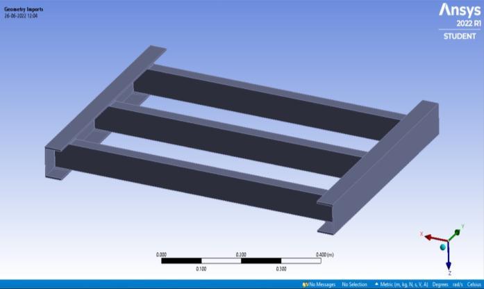
As illustrated in the diagram, the chassis geometry is put togetherwiththefollowingparts.Thelong-members,crossmembers, and C-clamp are all part of the chassis frame geometry. Because these parts are identical, they can be mounted together appropriately to form a whole chassis assembly.Twooftheselong-members,threeofthesecrossmembers, and six of these C-clamps were utilized for the chassissub-assemblyalone.
Non-ConventionalorFramelessChassis
It's also known as a uni-body chassis or a frameless chassis. This chassis does not have a ladder frame; instead,thebodyservesasaframe.Italsosupportsall of the vehicle's elements and components. These are commonly utilized on most modern vehicles in the samewaythattraditionalchassisare.
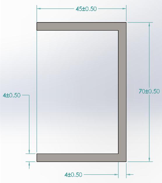
Followingtheresearch,extensiveexpertiseofconceptdesign with presumptive parameters, hand calculations, 3D modelling, material selections, and harvester operation systems with consideration of the target and objectives is gained.Thedesign'soutcomeswereassessedanddebated.A thorough conclusion is then reached in light of all the findings.
The chassis dimensional parameters were compared to informationinreferencejournalsandvalidatedwithIndian Standards (ISO) for practicality. Because this thesis is primarily concerned with cost reduction, all of the parts designedandusedherewillbemanufacturedofsheetmetal, whichiseasilyavailableandinexpensive.Alloftheplanned pieces were tested for production viability using conventional sheet metal forming techniques like curling, punching,andblanking.Thechassisstructurewasmadeout ofAISI1045MildSteel,whichisidealforourapplication.
Fig -1: Methodology
AISI 1045 is amedium tensile low hardenability carbon steelgenerallywithatypicaltensilestrengthrange570-700 MpaandBrinellhardnessrange170-210.Thistypeofsteel exhibitsmedium tensile strength, good weldability and machinability, and high strength. Typically used in machinery parts, die forging, hot upsetting, gears, crankshafts,shafts,axles,bolts,studs,pinions,casters,and supportplates.Itapproximatelyconstitutesof98.5%ofIron,
International Research Journal of Engineering and Technology (IRJET) e-ISSN: 2395-0056
Volume: 09 Issue: 09 | Sep 2022 www.irjet.net p-ISSN: 2395-0072
0.45%ofCarbon,0.74%ofManganeseandlessthan0.04% ofPhosphorous.
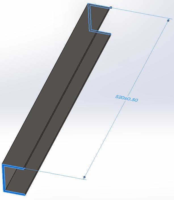
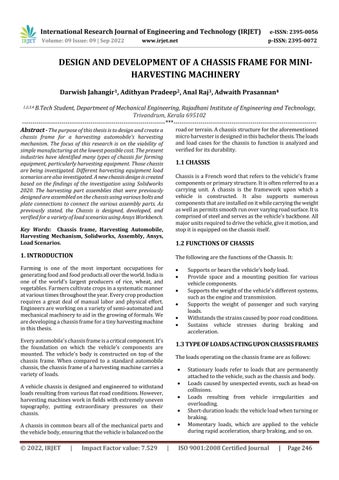
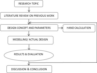
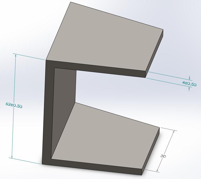
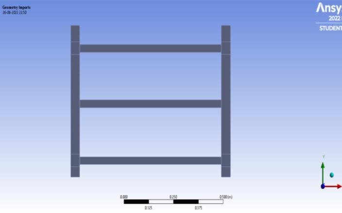
Similartothatillustratedinthefigures2and3,forthecrossmembers,thecross-sectionaldimensionsweregiven26mm, 54mm and a thickness of 4mm respectively whereas the lateraldimensionsweregiventhevalueof790mmallwitha toleranceof0.5mm.
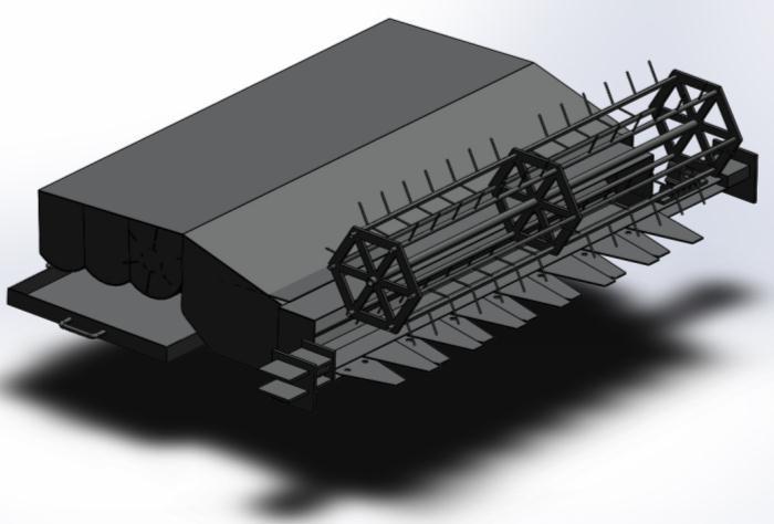
Figure 5 depicts the pre-designed assembly of harvesting machinerycomponents.Forpreliminaryloadestimates,this equipment is considered to be made of alloy steel. Each portionofthisapparatusisbuiltinsuchawaythatitmaybe made entirely of sheet metal, dramatically lowering the manufacturing costs. It was made a point throughout the designprocesstoavoidusingfilletorcurvesthatwouldbe incompatiblewithsheetmetalformingmethods.
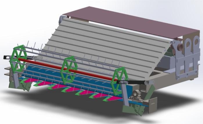
All of these parts were designed and developed in considerationwiththepresentdaysexistingoutlookofthe miniandconventionalharvestingequipment.
International Research Journal of Engineering and Technology (IRJET) e-ISSN: 2395-0056
Volume: 09 Issue: 09 | Sep 2022 www.irjet.net p-ISSN: 2395-0072
MPa
ElongationatBreak(in50 mm) 16.0% 16.0%
ReductionofArea 40.0% 40.0%
ModulusofElasticity (Typicalforsteel) 200 GPa 29000ksi
BulkModulus(Typicalfor steel) 140 GPa 20300ksi
PoissonsRatio(TypicalFor Steel) 0.290 0.290
Fig-7: Rear isometric view of the internal parts and connections of the harvesting equipment on the chassis frame
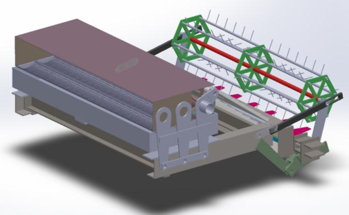
Table -1: CHEMICAL COMPOSITION
Element Content
Carbon,C 0.420-0.50%
Iron,Fe 98.51-98.98% Manganese,Mn 0.60-0.90% Phosphorous,P ≤0.040%
Sulfur,S ≤0.050%
Table -2: MECHANICAL PROPERTIES
Mechanical Properties Metric Imperial
Hardness,Brinell 163 163 Hardness,Knoop (ConvertedfromBrinell hardness) 184 184 Hardness,RockwellB (ConvertedfromBrinell hardness) 84 84
Hardness,Vickers (ConvertedfromBrinell hardness) 170 170
TensileStrength,Ultimate 565 MPa 81900psi TensileStrength,Yield 310 45000psi
ShearModulus(Typicalfor steel) 80GPa 11600ksi
Table -3: PHYSICAL
Physical Properties Metric Imperial
Density 7.87g/cc 0.284lb/in3
TheanalysisisdoneusingAnsysWorkbench2022R1.For themosteaseandsimplicityforanefficientanalysis,from variousreferencejournalsandpracticalinferences,thetotal loadconsiderationalongbyincludingafactorofsafetyof3 whichistheusualamountforfactorofsafetyconsideredfor steel, we came into the conclusion that 6000N is being appliedonthechassisframetotally.Fromrelevantjournals which focuses on the load cases acting upon the chassis framesshowsusthatthecross-membersofthestructures are the weakest part of the chassis were most amount of deformationduetotheapplicationsofloadoccurs.Alsofrom engineeringtheories,weknowthatifthecriticalpointonthe structure withstands the total amount of load, then it is definitethattheentirestructureasawholealsowithstands theload.Criticalpointisdefinedasthevirtualpointonany structurewhere when a loadisappliedisconcentrated at maximumdeformationisfound.Forourchassisframe,due totheabove-mentionedhighlightswecanassumethatthe criticalpointsisinthemiddlespanofthecross-members.
International Research Journal of Engineering and Technology (IRJET) e-ISSN: 2395-0056
Volume: 09 Issue: 09 | Sep 2022 www.irjet.net p-ISSN: 2395-0072
analysis, hence the horizontal support reactions are also neglected.
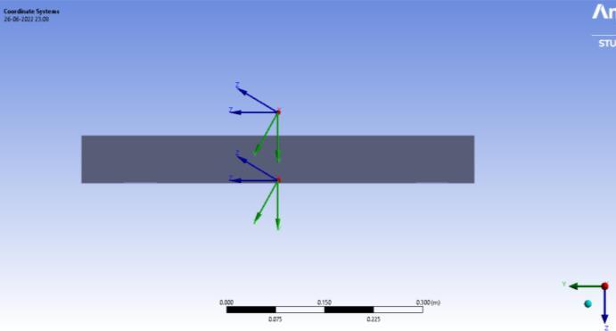
Aswecanseeinthediagramtherearetwocoordinatesfor the geometry, in which one of them corresponds with the coordinatesystemforthechassisframeassemblyandthe othercoordinatesystemwithitsoriginhappeningtobefrom thecentreofgravityoftheentiremachinerywhichincludes both the harvesting equipment, the chassis and the parts connectingthem.
Fig –9: Red
Ontheobservationthatasthatofeverycommonvehicle,this wouldalsotaketheuseoffour-wheelsmechanismforthe purposeofmotion.Thesefourwheelsprovidesupportsfrom 4 corner regions. On assuming the supports by the fourwheelmechanismasfoursupportreactions,wehaveapplied four-point loads at the places marked in red in the above given figure. This assumption was also made into considerationfromvariousreferencejournalsandpractical observations.
From the design we can see that the cross-members are attachedtothelong-membersinawaythatboththeendsof thecross-membersarefixedonthelong-memberwithaCclamp.Onrelatingthistotheengineeringtheories,wecan significantlyconsideritasabeamwithtwoendsfixed.For any beam with both ends fixed with have both horizontal andverticalreactionforcesatbothends.Sinceweconsider only vertical forces being applied for now, which also the majorforcehere,thehorizontalforcesareneglectedforthe
Ondetailedstudies,foraparticularloadconditionforour analysiswhenthemachineryismovingalonga30-degree inclinedpath,thesameloadistobeappliedwith30-degree inclinationwithrespecttotheverticalaxis(yaxis).Forthe same reason one more axis is created with 30 degrees of inclination with the vertical axis as like the above given figuredemonstrates.
Ondefiningtheconnectionsfortheanalysisoftheimported geometry,theinputwasgiventhatallthecomponentsare connectedtoeachotherasperthegivenconstraintsandthe coincidentfaces.
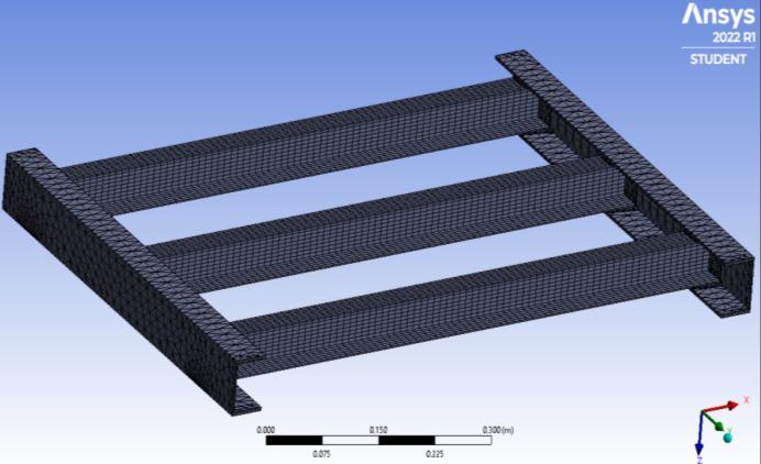
Theaboveshownmeshinthediagramisgeneratedwithan elementsizeof1.e-002m(1.094x10⁻²m)whichwasgivenby theadaptivesizingfunctionavailable.Theelementsofmesh forthelongmemberswereconsideredtriangleandforthe Cross-members were considered rectangle. That is also taken into consideration for generating meshes from referencejournalsofsuchanalysis.FortheC-clampsalsothe elementswereconsideredtriangles.Fromthedetailedmesh report available in the software, we can see that the total number of nodes are 78776 and the total number of elementspresentinthisgeometryis21852.
International Research Journal of Engineering and Technology (IRJET) e-ISSN: 2395-0056
Volume: 09 Issue: 09 | Sep 2022 www.irjet.net p-ISSN: 2395-0072
Fig -10: View of mesh for the analysis
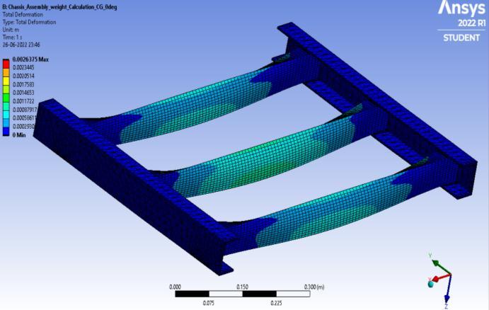
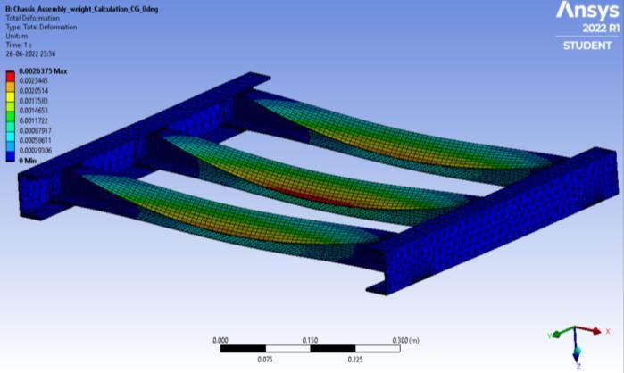
Aspertheanalysisconsiderationspreviouslymentionedin thisthesis,forthepracticalcasewhereonlythedeadloadof the harvesting machinery is acting upon it when the machineryisstaticorkeptstationery,thedeformationfor thisscenarioisobtained.
Fig -12: Isometric view of the deformation due to 0degree static load
5.2 STATIC LOAD AT 300 INCLINATION
Fromtheimagewecanseethatthemaximumdeformation happening here is 0.0026375m which is visible to be happeningatthepreviouslyassumedcriticalpointregionon thecross-member.
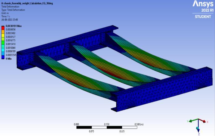
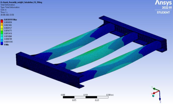
On considering the practical application where the harvestingmachinerytakingitspathofmotionalonga30degree inclined terrain, the static load due to the gravitational force would act in a way that it is acting inclined as much with respect to the inclination of the terrain. For that case study, we have inclined the load appliedatanangleof30degreeswithrespecttothevertical axis(yaxis)ofthecoordinatesystememployedforanalysis. Thedeformationforsuchacaseisthusobtained.
From the analysis, we can see that the total magnitude of deformation occurred is 0.0030191m which also located nearthecriticalpointregionofthecross-memberasstudied earlier.
International Research Journal of Engineering and Technology (IRJET) e-ISSN: 2395-0056
Volume: 09 Issue: 09 | Sep 2022 www.irjet.net p-ISSN: 2395-0072
Fig -14: Isometric view of deformation due to 30degree static load
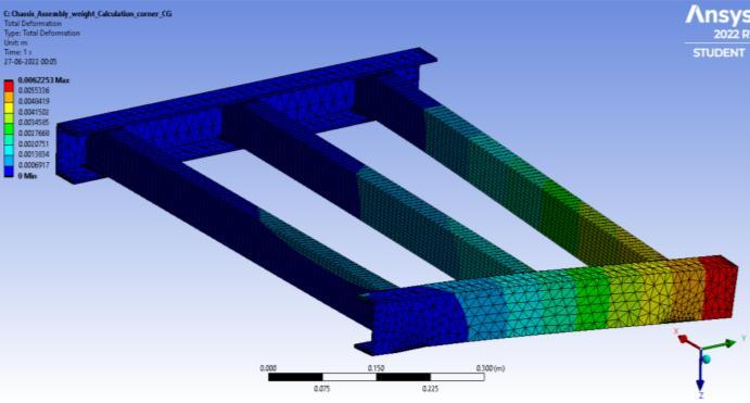
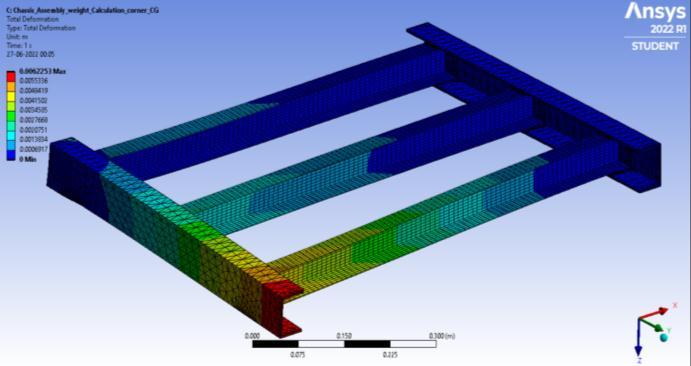
This load condition came into consideration when in a practicalscenariowhenoneofitstyresfallsintoapitchor breakssothatitfailstoprovidethesupportthemachineryto rest normally. For this load condition study, we have removedoneofitssupportreactionsonthelongmemberand the dead load is applied vertically in order to act like the above-mentioned practical case and for this the total deformationisobtained.
Fig -16: Isometric view of the deformation when one of the support reaction fails
Fig -15: Deformation when one of the support reactions fail
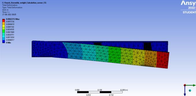
Hereitisobservedthatthetotaldeformation happeninghereis0.0062253mforthedescribedcase.
Fig -16: Side view of the deformation when one of the support reactions fail
6.1
Considering the cross-member as a beam with both ends fixed, but the horizontal support reactions are neglected becauseonlyverticalloadsareapplied,thereforethereisno necessityofhorizontalsupportreactionsbeingformed.
Thetotalloadof6000Nisappliedallalongthethreecrossmember,thereforeforthecalculationofdeformationfora singlebeam,weneedtoconsideronlyone-thirdofthetotal loadwhichis2000N.
Forasimplysupportedbeamcarryingapointloadof2000N eccentrically,
FromdatahandbookofKMahadevanweknow,maximum deflectionymax, Where, W=loadapplied
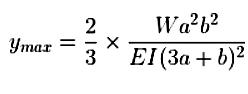
b=distancefrompointofloadappliedtotheright support
a=distancefrompointofloadtotheleftsupport
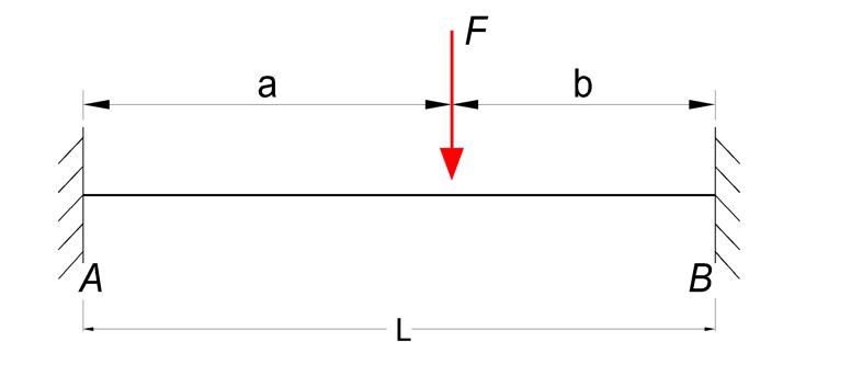
International Research Journal of Engineering and Technology (IRJET) e-ISSN: 2395-0056
Volume: 09 Issue: 09 | Sep 2022 www.irjet.net p-ISSN: 2395-0072
E=Young’sModulus
I=MomentofInertiaforaCSectionbeam Here, W=2000N a=395mm b=395mm E=205GPa(AISI1045Steel)
aandbareequalastheloadisconsideredasapointload hereactinguponthecentreofcross-member,butinreal lifepracticethepointofloadappliedmaydiffer,thusthe equationforeccentricloadingisemployed.
MomentofInertia‘I’forCsection(fromK.Mahadevan Datahandbook), I=[bd3 –h3(b-t)]/12
ymax=2.598mmwhichisequalto 0.002598mofdeflection
The obtained result on numerical calculation for deformationisalmostsimilartothedeformationobtained on the computational analysis for the respective load condition. Hence the obtained results are successfully verified.
The difference between the value of the deformation obtainedfromthenumericalcalculationandthesimulation calculation has a negligible difference of 0.032mm. This impliesthattheloadcasescalculationsthroughsimulation aresufficientlyaccurateandcanbeconsideredastheresult ofthestudy.
For both the 0 degree and 30-degree inclined load applicationitisobservedthatthemaximumdeformationis happening at the maximum allowable limit on the application of 6000N. The load of 6000N was considered includingafactorofsafetyof3forsteelasusual,whichalso makes it evident that practically this load is safe for the chassistowithstand.
Since the aim of this thesis was to study the practical feasibilityofmanufacturingachassisframewithsheetmetal, from the above static load conditions it is visible that it is visiblethatforthisapplicationasthechassisforharvesting machineryitisreliable.
Theprimaryobjectiveofthedesignistoreducethecostof thefinalproductbyinvolvingsheetmetaltomanufactureall ofthenecessarycomponentsforthisharvestingmachinery andhencefoundsuccessfulinthataspecttoo.
Fig -17: Cross sectional dimension of the cross member is illustrated in this diagram
Here, b=26mm d=54mm t=4mm h=50mm
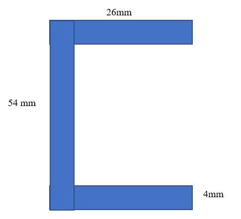
Forthegivenvalues, MomentofInertiaI=112005.33kgmm2 Thus,onsubstitutingalltheobtainedvaluesinthe equationformaximumdeflection,
Itisfoundthatthechassisfailstowithstandtheloadonthe thirdloadcasestudywhereoneofthesupportreactionsfail. In that particular point of view, this thesis can be further studiedtoovercomethefailurehappeninginthatinstance whichmakesthisconceptofusingsheetmetalforchassisa totalsuccess.
Firstandforemost,Iconcedethesurvivingpresenceandthe flourishing refinement of almighty GOD for his concealed handyetsubstantialsupervisionallthroughtheseminar.
IextendmysinceregratitudetoourPrincipal Dr. S. SURESH BABU., to his countenance towards the successful accomplishmentofthecourse.
Isincerelythank Dr. BINDU S.S.,HeadoftheDepartmentof Mechanical Engineering for valuable support, comments, advice,guidanceandconstantencouragementthatenables metocompletetheseminarontime.
2022, IRJET | Impact Factor value: 7.529 | ISO 9001:2008 Certified Journal | Page253
International Research Journal of Engineering and Technology (IRJET) e-ISSN: 2395-0056
Volume: 09 Issue: 09 | Sep 2022 www.irjet.net p-ISSN: 2395-0072
I am thankful to my project guide Mr. SREERAJ M P., Assistant Professor and project coordinator Mr. KRISHNAKUMAR K., Assistant Professor in Mechanical Engineeringdepartmentforhisvaluablesupportandadvice.
IalsoexpressmyindebtthankstoalltheteachingandnonteachingstaffsofMechanicalEngineeringdepartment.
Finally,Iamgratefultomyparents,familymembersandmy beloved friends for their help, encouragement and moral supportgiventomeduringthecourseofwork.
[1] D. Kornack and P. Rakic, “Cell Proliferation without NeurogenesisinAdultPrimateNeocortex,”Science,vol. 294, Dec. 2001, pp. 2127-2130, doi:10.1126/science.1065467. Apata, T. G., Linkages between Crude-oil Exploration and Agricultural Development in Nigeria: Implications for relevant qualitativedatacollectionandanalysistoimproverural economy.,2010.
[2] Olajide,O.T.,Akinlabi,B.H.,andTijani,A.A.Agriculture ResourceandEconomicGrowthinNigeria.2012.
[3] Engineering Export Promotion Council (EEPC), AgriculturalMachinery,PartsandTractorsMarketin Nigeria.,2013.
[4] Talabi,S.O.andOnasanya,O.AgriculturalIntroduction. 201322/09/2014]
[5] Faborode, M. O. Strategies for sustainable National Agricultural Infrastructures Development. in SustainableEngineeringInfrastructuresdevelopment. PortHarcourt:TheNigerianSocietyofEngineers,2001.
[6] Akande, L. O., Empowerment of the Rural People throughAgriculturalMechanization,OsunStateCollege ofEducation,2006.
[7] Lamidi, W. A. and Akande, L. O., A Study of Status, ChallengesandProspectsofAgriculturalMechanization inOsunState,Nigeria.1(1):p.001-008,2013.
[8] Takeshima,H.andSalau,S.,AgriculturalMechanization and the Smallholder Farmers in Nigeria; Nigeria strategysupportprogram,2010.
[9] Abdulkareem, Y. A., Indigenous Technology, Past, PresentandFutures,inWorkshopfortheProcessingof Raw Materials: Raw Materials Research and DevelopmentCouncil,1992.
[10] Adamade, C. A. and Jackson, B. A., Agricultural mechanization:astrategyforfoodsufficiency.Scholarly JournalofAgriculturalScience.4(3):p.152-156,2014.
[11] Asoegwu, S., Agricultural Field Implements and Mechanization.,1998.
[12] André-Michel, E. Despite recovery, Africa needs morejobs,saysECA.2016.
[13] Quick, G. R. and Buchele, W. F., The Grain Harvesters.Americansocietyofagriculturalengineers., 1978.
[14] Olukunle,O.T.,DevelopmentsinGrainHarvesting Mechanisation.JournalofAgriculturalEngineeringand Technology(JAET).18(1),2010.
[15] AMRI, Test Report Indian Combine Harvester SWARAJ-8100, Agricultural Mechanization Research Institute (AMRI), Multan Government of the Punjab, Lahore,2014.
[16] Ademosun,O.C.,Adewumi,B.A.,Olukunle,O.J.,and Adesina,A.A.,DevelopmentofIndigenousMachinesfor Weeding and Grain Harvesting: FUTA Experience. FUTAJEET3(2):p.77-84,2003.
[17] BioSatAgriculturalBiomassSources.2016.
[18] Karande, O., Gauri, S. K., and Chakraborty, Applications of Utility Concept and Desirability FunctionforMaterialsSelection.Material andDesign Journal45:p.349-358,2012.
[19] Shackelford,J.F.,IntroductiontoMaterialsScience forEngineers.Fifthed.:PrenticeHall,2000.
[20] Granta, Cambridge Engineering Selector (CES), GrantaDesignLimited,UK,2014.
[21] Childs, P. R. N., Mechanical Design. Second ed.: Oxford:Butterworth-Heinemann,2003.
[22] Khurmi,R.S.andGupta,J.K.,ATextbookofMachine Design. Ram Nagar, New Delhi: Eurasia Publishing house,2005.
[23] Pahl, G., Beitz, W., Feldhusen, J., and Grote, K.- H., Engineering Design: A system Approach. Thirded., London:Springer-Verlag2007.
[24] Sapuan, S. M., A knowledge-based system for materialsselectioninmechanicalengineeringdesign. Materials&Design.22(8):p.687-695,2001.
2022, IRJET | Impact Factor value: 7.529 | ISO 9001:2008 Certified Journal | Page254