International Research Journal of Engineering and Technology (IRJET) e-ISSN: 2395-0056

Volume: 09 Issue: 09 | Sep 2022 www.irjet.net p-ISSN: 2395-0072
International Research Journal of Engineering and Technology (IRJET) e-ISSN: 2395-0056
Volume: 09 Issue: 09 | Sep 2022 www.irjet.net p-ISSN: 2395-0072
1P.G Scholar, Bhilai Institute of Technology, Raipur, Chhattisgarh 2,3Assistant Professor, Dept. Mech. Engineering, Bhilai Institute of Technology, Raipur, Chhattisgarh ***
Abstract – As one of the most noticeable objects on construction sites and a symbol of modern construction operations, cranes possess the capacity of lifting heavy loads and maneuvering the loads over long spans. When properly located on a site, cranes can strategically lift and lower loads to virtually any desired location on a construction site. Unfortunately, when large numbers of cranes have been dispatched to a construction site, the hazard exposure also increases for construction workers who work with, around or under these cranes. The more important aspect ofthese cranerelated fatalities is that they were totallypreventable ifproper safety precautions had been taken and workers are properly equipped with knowledge of hazard self-perception.
The objective of this study is to evaluate the effectiveness of the fuzzy TOPSIS method for the evaluation of hazards using expert’s views aiming to minimize the hazard exposure of construction workers during lifting of heavy consignments.
Key Words: LiftingOperation,LiftPlan,Crane,TOPSIS,Fuzzy Logic
Rigging and lifting are the key process of handling heavy materialswhichcomesunderthecomprehensivesubjectof “Material Handling” in which load is initially secured and then arrangements are made for its pre-determined movementlikepushing,pulling,lifting,carryingandshifting from one destination to other. Rigging generally involves binding, securing and preparing the load to be relocated whereasthemovementofloadopposinggravitationalpullis lifting.
Applications of rigging and lifting process by means of cranes can be seen everywhere around the world. Cranes have major applications in transport industry for loading andunloadingcargo,inmanufacturingindustrytotransfer andlumptogetherheavyloads,inconstructionindustryto transfer material from ground level to an elevated level. Other applications of crane can be seen in Glazing Works, Skyscrapers, Rooftop Work, Civil Engineering and Major Erection Projects, Residential Construction, Industrial Maintenance (Plant, Factory & Automotive), Electric & Nuclear Power Plants, Confined Areas, Railways, Marine,
Ports & Harbours, Aviation Industry & Airports, Oil & Gas industries.
InallthemetrocitiesinIndiaandaroundtheworld,cranes canbeseenworkingawayataconstructionsiteofhighrise buildingorskyscrapers.Liftingequipmentplaysavitalrole inreachingnewheightsinconstructionindustrywithlatest and technically advance cranes which can comfortably securetonnesofloadandmoveitaround.Overallitcanbe said the lifting crane has made the work easier for the workerandacceleratedtheefficiencyofwork.
Theconceptofliftingheavyobjectsisnotsomethingnewto humans,therehasbeensomearrangementandpracticeof liftingdatingbackforaslongashumansrequiredtoliftand moveobjectswhichweretooheavyfortheirbarehandsto liftandmove.Theforemostidentifiedcrane-like-toolwasa water-lifting device with a lever mechanism named “shadoof” which was invented in ancient Mesopotamia around 3000 BC and then later seen in ancient Egyptian technology(circa2000BC).
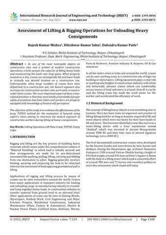
Thefirstdocumentedconstructioncranesweredeveloped bytheAncientGreeksandweredrivenbymen,horsesand donkeys. During the Renaissance age, architect Domenico Fontanain1586erectedVaticanObeliskhavingaheightof 83.6feetweighsaround331tonsonPeter'sSquareinRome withthehelpofaliftingtowerwhichtookaconcertedeffort ofaround900menand75horsesandcountlesspulleysto erectthismonumentwhichstandstilltoday.
International Research Journal of Engineering and Technology (IRJET) e-ISSN: 2395-0056
Volume: 09 Issue: 09 | Sep 2022 www.irjet.net p-ISSN: 2395-0072
Theearliestcraneswerebuiltfromwood,butcastironand steel replaced them with the imminent of the Industrial Revolution. With the commencement of the Industrial Revolution the foremost modern cranes were mounted at harboursforloadingcargo.Intheyear1834,firstcastiron cranewasconstructed.
Till the early nineteenth century, the Vatican obelisk remainedthepointofreferenceforalltheengineersthathad to transport heavy loads and above all large monoliths. Later,LeBas’liftingdevicecanbeconsideredaturningpoint mostlyforitssubstantialdifferencefromFontana’smodel. Finally,in1851,thepathbreakinginnovationofthesteam powered crane was made which was the foremost step toward a truly hydraulic crane. With the arrival of steam powerincrane,anyloadcouldbeliftedatdesiredspeed,as longastheenginewaspowerfulenough.
Figure 1 ConstructionsiteoftheVaticanobelisk(1586) (CarloFontana,1694)[1]
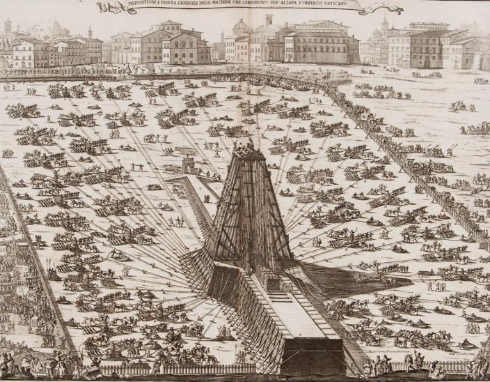
Another historical engineering marvel which involved securingandmovingheavyobjectwasdisplayedbyMarinos Charvouris in 1769/1770 for the transportation of the ThunderStoneofSaintPetersburg.TheThunderStoneisa massive granite boulder meant to form the base of the bronzehorse-ridingstatueofPetertheGreat.Itwasclaimed tobethelargeststoneevermovedbymanweighing1250 tons.ItwasbroughttoSaintPetersburgpartlyoverlandand partly through sea from Finland. Marinos Charvouris developeda systemofball bearingsabove whichthe rock was moved horizontally. In the meanwhile, stonecutters continuedtosilhouettetheenormousgraniteinasweatto shedweightsothatitstransportationwaseasier. Whenit wasextractedfromtheground,theboulderweighedmore than1,500tons.BythetimeitarrivedatSaintPetersburgit weighed1,250tons.Theworkoftransportingthestonewas doneentirelybymen;noanimalsormachineswereusedin theprocess.[2]
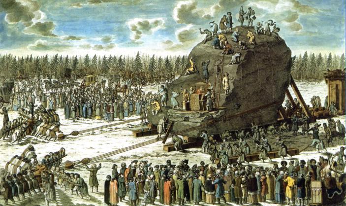
In 1878, the obelisk of London (Cleopatra's Needle) weighing187tonswasre-erectedinLondonliftedbymeans of hydraulic jacks instead of the tackles and capstans previously used. Similarly, in the year 1881, the second Cleopatra’s Needle (Obelisk of New York) was lifted by meansofhydraulicjacks.
[3]
Figure 2 Thetransportationofthethunder-stone. (Y.M.Felten,1770)
Earlierto1870craneshadfixedpositionhavingrestricted movement.Later,cranewhichoperatedwithsteampower were manufactured by Appleby Brothers at Paris in 1867 andViennain1873.ApplebyCrop.startedtomanufacture truck-mountedcranesin1922.In1992,theadoptionofthe
International Research Journal of Engineering and Technology (IRJET) e-ISSN: 2395-0056
Volume: 09 Issue: 09 | Sep 2022 www.irjet.net p-ISSN: 2395-0072
internal combustion engine and the development of telescopic jibs took place which were some key steps in developing crane. In 1960, cranes were made to increase theirheightwhichamplifiedoperationcosts.Later,different crane manufacturing companies developed advanced telescopichydraulicboomtechniquesanddrivemechanism whichbroughttogetherseveralstateoftheartdevelopment.
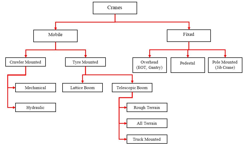
Onthebasisofpresentcranestudyanddevelopmentcranes canbecategorizedintwogeneraltypes:
1. Fixedcrane
2. Mobileormovablecrane
3.
Afixedcraneorstationarycraneisthetypeofcranewhich lift the loads without any appreciable movement. Fixed
cranesarebroadlyusedonbuildingconstructionworksites as well as on other construction projects which requires enormousverticalclearancesandhaverestrictedspacein theworkzone.Thesetypeofcranesareabletomoveloads over a wide area in and around work zone and have an almostunlimitedverticalrange.
Amobilecraneisthetypeofcranewhichmovesfromone place to another as well as movement of the crane basic tools.Mobilecranesarebroadlyusedinconstructionasthey aremadetomovefreelyaroundaconstructionsite.Rubber tired cranes are also capable of moving rapidly between constructionprojects.Crawlercranesalsohavetremendous mobility however it must be transported on equipment trailersbetweenconstructionprojects.Inthisresearchwork, the main work iscarried outfor mobile crane,hence only mobilecraneswillbefocusedhere
Roughterraincraneisacranemountedonanundercarriage with four rubber tires that is designed for pick-and-carry operationsandforoff-roadand"roughterrain"applications.
Liftingcapacity:200tonsat3mworkingradius
The rough terrain crane is used for building bridges, operationsinpowerandchemicalplantsandrefineries andforlarge-scaleprojects.
Thesecranesaremountedontwo-axlecarriers.
Theseunitshavealowercost.
2022, IRJET | Impact Factor value: 7.529 | ISO 9001:2008 Certified Journal |
International Research Journal of Engineering and Technology (IRJET) e-ISSN: 2395-0056
Volume: 09 Issue: 09 | Sep 2022 www.irjet.net p-ISSN: 2395-0072
Theseunitsareequippedwithunusuallylargewheels andcloselyspacedaxlestoImprovemaneuverabilityat thejobsite.
Theyfurtherearntherighttotheirnamebytheirhigh ground c1earence allowance, as well as the ability of somemodelstomoveonslopesofupto70%.
Mostunitscantravelonthehighwaybuthavemaximum speedsofonlyabout30mph.
Inthecaseoflongmovesbetweenprojects,theyshould betransportedonlow-bedtrailers.
A mobile crane with the necessary equipment to travel at speedonpublicroads,andonroughterrainatthejobsite using all-wheel and crab steering. AT‘s combine the road abilityofTruck-mountedCranesandthemaneuverabilityof RoughTerrainCranes.
Liftingcapacity:upto300tons
Workingradius:34m
All-terrainmobilecranesareexcellentforuseinplaces where ground is uneven or not very accessible like a beachorarockyexpanse.
Designedforlong-distancehighwaytravel.
The carrier has all-axle drive and all-wheel steering, crabsteering,largetires,andhighgroundclearance.
All-terrain cranes have dual cabs, a lower cab for fast highwaytravel,andasuperstructurecabthathasboth driveandcranecontrols.
Most appropriate machine when multiple lifts are requiredatscatteredprojectsitesoratmultiplework locationsonasingleproject.
It has a higher cost than an equivalent capacity telescopingtruckcraneorrough-terraincrane.
All-terrain machine can be positioned on the project without the necessity of having other construction equipmentprepareasmoothtravelwayastruckcranes wouldrequire.
A crawler crane is a crane mounted on an undercarriage with a set of tracks (also called crawlers) that provide stabilityandmobility.
Liftingcapacityfromabout35to40tones
This particular asset class is ideal for working in confinedorsmallareawhereabigcranecannotreach.
Crawlercranecommandtheirpositionatmanyofpower plants,thermalplantsandatbiginfraprojects.
Thesecranearewellsuitedforpiling,drillingandpipe layingoperationbyjustaddingsuitableattachment.
Thefullrevolvingsuperstructureofthistypeofunitis mountedonapairofcontinuous,parallelcrawlertracks.
The crawlers provide the crane with good travel capabilityaroundthejobsite.
Inclinedlatticemast,whichhelpsdecreasecompressive forcesintheboom.
Relocating a crawler crane between projects requires thatitbetransportedbytruck,rail,orbarge.
Thesemachinesusuallyhavelowerinitialcostperrated liftcapability,comparedwithothermobilecranetypes, butmovementbetweenjobsismoreexpensive.
Therefore,crawler-typemachinesshouldbeconsidered for projects requiring long duration usage at a single site.
Telescopicboomcranesaretypicallycalledhydrauliccrane.
These truck-mounted cranes have a self-contained telescopingboom.
Most of these units can travel on public highways between projects under their own power with a minimumofdismantling.
Thesemachines,however,havehigherinitial costper ratedliftcapability.
Forsmalljobsrequiringcraneutilizationforafewhours toacoupleofdays,atelescopingtruckcraneshouldbe preferred.
Telescoping-boom truck cranes have extendable outriggersforstability.
The booms are composed of a series of rectangular, trapezoidal, or other shape of symmetrically crosssectionalsegments,fittingintoeachother.
Thelargestsegment,atthebottomoftheboom,iscalled thebasesectionorboombutt.
Thesmallestsection,atthetopoftheboom,iscalledthe tipsectionorboomtip.
Inbetweentherecanbeoneormoresectionscalledthe first,second,andsoforth,sections.
With the boom fully retracted, the telescopic boom craneishighlymanoeuvrableandeasytotransportto jobsites.
The lattice-boom truck crane has a fully revolving superstructuremountedonamultiaxletruck/carrier.
Theadvantageofthismachineisthelatticeboom.The lattice-boomstructureislightweight.
This reduction in boom weight means additional lift capacity, as the machine predominately handles hoist loadandlessweightofboom.
The lattice boom does take longer to assemble. The lightweightboomwillgivealessexpensivelattice-boom machine the same hoisting capacity as a larger telescoping-boomunit.
International Research Journal of Engineering and Technology (IRJET) e-ISSN: 2395-0056
Volume: 09 Issue: 09 | Sep 2022 www.irjet.net p-ISSN: 2395-0072
The disadvantage of these units is the time and effort requiredtodisassemblethemfortransport.Inthecase ofthelarger units, it maybe necessaryto removethe entireSuperstructure.
Alatticeboomresemblespipepiecesconnectedtogether.It iscablesuspendedandactsasacompressionmember.The structureislightweight,whichmeansextraliftingcapacity. This boom is usually transported in sections that are assembled at the site. Crawler and tower cranes typically have lattice booms. Most heavy lifting is done with lattice booms.
A telescoping boom works in the same manner as a retractabletelescope. Aslift height isneeded,the boom is telescopedorextended.Thisboomactsabendingmember when lifting. Typically, the boom comes ready for lifting whenitarrivesatthesite.Mobilehydrauliccranes,skytrack type lifters use telescoping booms. Moderate to medium liftingcanbedonewithtelescopingbooms.
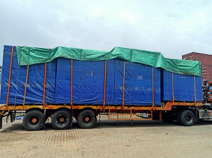
In order to lay the foundation for the research with a problem statement, a visit to JM Warehouse, Fatehpur, Harayana was made by the author. The visit provided exposure to real working environments along with a practical perspective of a theoretical concept relevant to material handling domain. Few significant benefits of the conductingavisitaregivenbelow:
A chance to meet industry leaders, professionals, entrepreneurs,policymakers,andcorporateswhoshare theirwisdom,learning,andexperiences.
Toseeandexperiencerealunloadingstations,machines, systems and interact with highly trained and experiencedpersonnel.
Tolearnaboutcompanypoliciesintermsofproduction, quality,andservicemanagement.
To open many doors for corporate training and internships,whichinturnincreasetheemployability.
To understand how managers, engineers, employees workintandemtoachieveacommontarget,whichisa managementlessoninitself.
To identify the learning towards safety and to decide futureworkareaslikelifting,rigging,signalling,safety etc.
Inthisresearchwork,onlyunloadingofheavyconsignments from Truck Trailers are covered using cranes. Table 3.2 showsthedetailsofdifferentconsignmentsalongwiththeir
Technique for Order of Preference by Similarity to Ideal Solution (TOPSIS) is a multi-criteria decision analysis method(MCDA)whichwasdevelopedbytworesearchers Hwang & Yoon, (1981). TOPSIS was further modified and improved by Yoon, (1987) and Hwang et al., (1993). This MCDA works on the primary concept of collection of alternative next to the ideal and extreme away from the negative.
Here,theIdealsubstituteisthebestsuitablefeaturewhich may be maximum or minimum depending on the type of
International Research Journal of Engineering and Technology (IRJET) e-ISSN: 2395-0056
Volume: 09 Issue: 09 | Sep 2022 www.irjet.net p-ISSN: 2395-0072
criteria Although, Negative ideal alternative is the foulest attribute value which can also be maximum or minimum dependingonthetypeofconditions.
The conventional technique of Technique for Order of Preference by Similarity to Ideal Solution is to pick out distinct positive ideal solution (PIS) and distinct negative ideal solution (NIS) of the problem, calculate the distance fromrespectivelysubstitute toPISandNIS,then compare theratiostandardsoftheseconddistancetothesumofthe two remoteness and advances the final ranking of the options.
Sincetheweightsofcriteriainproblemhavedifferentmean andimportance.Therefore,thenormalizedvalueiscomputed as:
Eq.(3)
Theweightiscomputedbydirectassignationbytheauthor onthebasisofthefieldexperience.
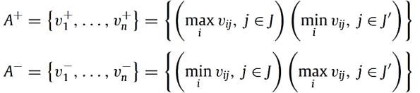
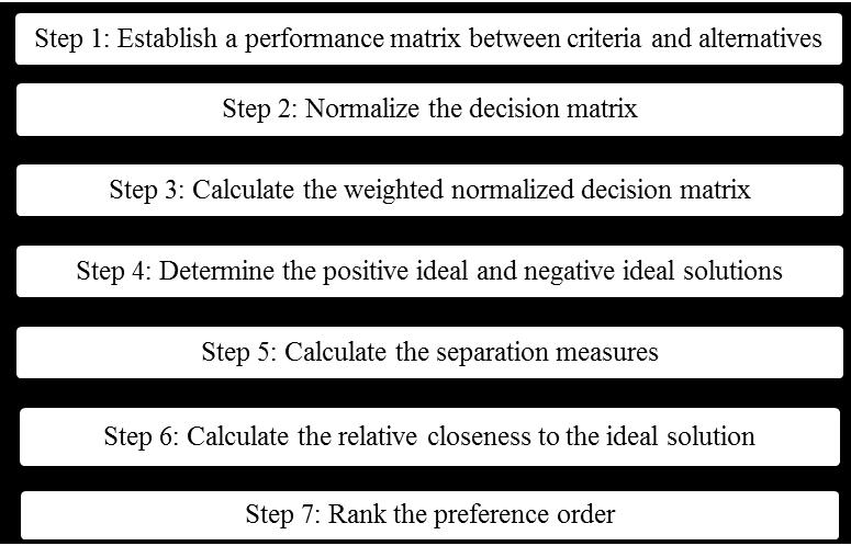
Step 4: Determine the positive ideal and negative ideal solutions
The positive ideal and the negative ideal value set ‘A’ are computedasfollows: Eq.(4) Eq.(5)
Intheaboveequation,Jislinkedwithbenefitcriteria,andJ'is linkedwithNon-benefitcriteria.
Step 5: Calculate the separation measures
Figure 6 TOPSISprocessflowchart
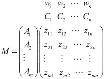
Step 1: Establish a performance matrix
Theperformancevalueofthealternativesisdenotedbyzij withrespecttosomeattribute(A)/criterion(C);
Eq.(1)
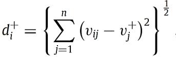
The distance of each alternative from the positive ideal solution(PIS)A+is: Eq.(6)
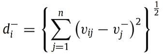
Thedistanceofeachalternativefromthenegativeideal solution(NIS)A-is: Eq.(7)
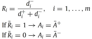
Step 6: Calculate the relative closeness to the ideal solution
The relative closeness “R”, to the ideal solution can be expressedas:
Step 2: Normalize the decision matrix
Thefollowingtransformationequationcanbeusedtoobtain thenormalizedperformancematrix. Eq.(2) j=1,……….,n,i=1,…………,m.
Step 3: Calculate the weighted normalized decision matrix
Eq.(8)
TheclosertheRiisto1,thehigherthewillbethepriority.
Step 7: Rank the preference order
Rankthesuitablealternativeindecreasingorderonthebasis ofRi
International Research Journal of Engineering and Technology (IRJET) e-ISSN: 2395-0056
Volume: 09 Issue: 09 | Sep 2022 www.irjet.net p-ISSN: 2395-0072
Basedontheavailabledataofcraneaccidentsandprevious studies discussed in Section 1, the most common hazards associatedwithcraneaccidentsresponsibleforfailureare: :StruckbyLoad
CrushedDuringAssembly/Disassembly
FailureofBoom/Cable
CraneTipOver
StruckbyCab/Counterweight
Falls
In order to assess these hazards in terms of the risk they havetohumanlifeFuzzyTOPSISmethodologyisused.The step-by-step process of implementing Fuzzy TOPSIS is discussedinSection3.Theassessmentofriskiscarriedout by rigorous one-on-one interview with the operators, supervisor,signaler,riggerandsafetyofficer.
Itisessentialtotakeintoconsiderationtheviews,comments andsuggestionsofthefieldexpertsinordertounderstand themajorissuesduringanyoperation.Therefore,unbiased viewsofexpertsweretakenbyone-on-oneinterviewduring thevisitassoonastheunloadingoperationended.Inorder tokeeptheidentityoftheintervieweehidden,thenamesof expertshavebeennumberedinthetablebelow:
Table 4.1 Detailsofinputsfromexpertsonlikelihood, severityanddetectabilityofdifferenthazards
Alt-03 Crushed During Assembly/Di sassembly
Expert9 3 4 2 Expert10 2 5 3 Expert11 4 4 2 Expert12 2 4 2
Expert1 2 2.50
3 3.42
Expert2 2 3 4 Expert3 2 4 3 Expert4 3 3 3 Expert5 3 4 4 Expert6 4 3 4 Expert7 3 3 4 Expert8 2 3 3 Expert9 3 4 3 Expert10 2 3 3 Expert11 2 4 4 Expert12 2 4 4
3 3.50 9.42
Alt-01 Struckby Load
Expert1 4 3.58
4 3.58
Expert2 4 4 5 Expert3 4 3 5 Expert4 4 4 5 Expert5 3 3 4 Expert6 4 3 5 Expert7 3 4 4 Expert8 3 3 5 Expert9 3 4 5 Expert10 3 3 4 Expert11 4 4 5 Expert12 4 4 5
5 4.75 11.92
Alt-04 Failureof Boom/Cable
Expert1 1 1.58
5 4.50
Expert2 1 5 2 Expert3 2 5 3 Expert4 2 4 2 Expert5 2 5 2 Expert6 2 4 3 Expert7 1 4 2 Expert8 2 5 2 Expert9 2 4 2 Expert10 2 4 3 Expert11 1 5 2 Expert12 1 4 3
2 2.33 8.42
Alt-02 Electrocution
Expert1 3 2.83
5 4.42
Expert2 3 5 3 Expert3 3 4 3 Expert4 3 5 3 Expert5 2 4 2 Expert6 2 4 2 Expert7 3 4 3 Expert8 4 5 2
2 2.42 9.67
Alt-05 CraneTip Over
Expert1 4 3.42
5 4.67
Expert2 3 5 3 Expert3 4 5 4 Expert4 3 4 3 Expert5 3 5 4 Expert6 4 5 4 Expert7 3 4 4 Expert8 2 5 4 Expert9 3 4 5 Expert10 4 5 3 Expert11 4 4 4 Expert12 4 5 4
4 3.83 11.92
Alt-06 Struckby Cab/Counter weight
Expert1 3 2.67
3 2.67
Expert2 2 2 4 Expert3 3 3 4 Expert4 3 3 5 Expert5 3 2 5 Expert6 2 2 4 Expert7 2 3 4 Expert8 3 3 5 Expert9 3 2 5 Expert10 3 3 5 Expert11 2 3 4 Expert12 3 3 5
4 4.50 9.83
Alt-07 Falls
Expert1 4 3.50
3 2.50
Expert2 3 2 4 Expert3 4 3 5 Expert4 4 2 5 Expert5 4 2 5 Expert6 2 3 5 Expert7 3 2 5 Expert8 4 3 5 Expert9 3 3 4 Expert10 4 2 5 Expert11 4 3 4 Expert12 3 2 5 Weight - 0.3 - 0.4 - 0.3 1
5 4.75 10.75
International Research Journal of Engineering and Technology (IRJET) e-ISSN: 2395-0056
The next task is to categorized the criteria between beneficiaryandnon-beneficiarycriteria.Aslowercountof likelihoodandseverityisdesirable,hencetheycomeunder Non-beneficiarycriteria
Furthermore, the next step involves the assignment of proper weightage is assigned to likelihood, severity and detectability.
Table4.2Allocatedvalueofweightagetothecriteria
Criteria
Likelihood Severity Detectability SUM Cr-01 Cr-02 Cr-03
Weightin decimal 0.3 0.4 0.3 1
Weightin percentage 30% 40% 30% 100%
The next step involves computation of Normalize the decision matrix using Eq.(2). Table 4.3 below shows the Normalize the decision matrix computed using the values obtainedinTable4.1
Table4.3Normalizeddecisionmatrix
S No. Likelihood Severity Detectability
Alternative-01 1.6486338 1.2878343 2.2166576
Alternative-02 1.0307305 1.9564773 0.5737793
Alternative-03 0.8024719 1.1708218 1.2035038
Alternative-04 0.3218804 2.0310032 0.5348906
Alternative-05 1.4988391 2.1842338 1.4436588
Alternative-06 0.9130346 0.7132192 1.9894655
Alternative-07 1.5728448 0.6268528 2.2166576
Now,usingEq.(3)theweightednormalizeddecisionmatrix ismadefromthevaluesofTable4.3.Table4.4alsoshows the determined the positive ideal (A+) and negative ideal solutions(A-)usingEq.(4)andEq.(5).
Table4.4Weightednormalizedmatrix
S No. Likelihood Severity Detectability
Alternative-01 0.4945902 0.5151337 0.6649973
Alternative-02 0.3092192 0.7825909 0.1721338
Alternative-03 0.2407416 0.4683287 0.3610511
Alternative-04 0.0965641 0.8124013 0.1604672
Alternative-05 0.4496517 0.8736935 0.4330976
Alternative-06 0.2739104 0.2852877 0.5968397
Alternative-07 0.4718535 0.2507411 0.6649973
A+ 0.0965641 0.2507411 0.1604672 A- 0.4945902 0.8736935 0.6649973
Thenextstepinvolvedthedeterminationofdistanceofeach alternativefromthepositiveidealsolution(PIS)A+,di+and Negativeidealsolution(NIS)A-,di -usingEq(6)andEq.(7)as shown in Table 4.5. Table 4.5 also shows the relative closeness (Ri)from the ideal solution for each alternative usingEq.(8).ThenonthebasisofRi values,thealternatives areranked.
Table4.5Rankingofalternatives
SNo. Ri Rank
Alternative-01 0.6949 0.3586 0.3404 2
Alternative-02 0.5729 0.5344 0.4826 3
Alternative-03 0.3292 0.5667 0.6326 7
Alternative-04 0.5617 0.6455 0.5347 5
Alternative-05 0.7662 0.2362 0.2356 1
Alternative-06 0.4723 0.6321 0.5724 6
Alternative-07 0.6288 0.6234 0.4978 4
Table4.6RankingofhazardsusingTOPSIS
Table 4.6 shows the ranking of hazards based on their likelihood,severityanddetectabilityrecordindescending order.Thesignificanceoftherankingobtainedintheabove tableistodeterminethehazardswithpastaccidentrecord requiringimmediateinterventionthroughpropertrainingof theworkers.Thisprioritizationofhazardsforworkspecific trainingwillhelptoidentifythedomainofworkwhichneeds moretraininginordertopreventanyaccident,incidentand nearmissinthenearfuture.
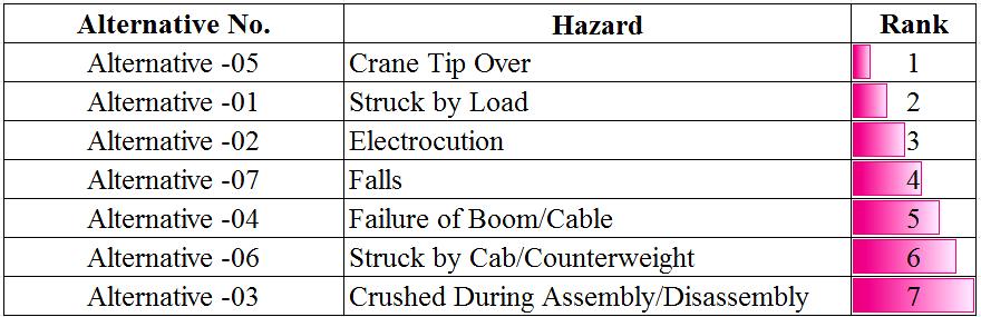
ItcanbeclearlyobservedfromTable4.6thathazardslike Crane tip over and being stuck by load have significantly contributedintherankingindex.Therefore,moreemphasis
Volume: 09 Issue: 09 | Sep 2022 www.irjet.net p-ISSN: 2395-0072 © 2022, IRJET | Impact Factor value: 7.529 | ISO 9001:2008 Certified Journal |
International Research Journal of Engineering and Technology (IRJET) e-ISSN: 2395-0056
Volume: 09 Issue: 09 | Sep 2022 www.irjet.net p-ISSN: 2395-0072
shouldbegiventothetrainingprovidedtotheworkerson thesehottopics.Whereas,thecontributionofotherhazards listedinTable4.6isveryless,thereforethereisnoneedto give more emphasisonspecific trainingto the workers of thesecompanies.Periodicgeneralsafetytrainingalongwith inductiontrainingshouldsufficethetask.
Theresearchsetsouttheresultofinvestigationperformed byauthorstoidentifythesafestapproachesforcarryingout heavyliftingoperationsusingcranessafelyfollowingallthe norms and regulations. The methodology adopted by the researchtoassessdifferentaspectsofsafetyweresuccessful in providing the desired outcome. The Fuzzy TOPSIS approachisusedtoranktherelevanthazardsduringlifting operation on the basis of likelihood, severity and detectabilityofthehazardsasrecordedbyinterviewingthe liftingexperts.Therankingapproachusedintheresearch for identification of hazards that need immediate work specifictrainingcanalsobeusedindifferentapplicationto setthepriorityofwork.Fewmajorconclusionsdrawnfrom theresearchalsoshowsthatthetrainingprogramdelivered to the especially to the operators and riggers were not meeting several aspects faced in the heavy lifting construction industry. Work specific training and task orientedtrainingisrequiredfortheworkersworkinginthe liftingjob.Also,Safetytrainingcontentsshouldcoverallthe hazardousaspectstowhichtheworkersareexposedduring liftingwork.But,itwasobservedthatwhiledesigningthe safety training programmes, no adequate care is taken in schemingthecontentsoftheprogrammes.
Astheliftingoperationcomesunderunorganisedsector,the parentcompanyshouldgivepropercarewhiledesigningand conceivingthesafetytrainingprogrammes.Administrators who are accountable for providing training for the workforcesshouldanalysetheusefulnessof suchtraining programmes.Itisestablishedthatsatisfactorystepsarenot available to take care of the effectiveness of such training programmes.
The future work in the research may involve the development ofa systemin placewhereinthefeedback is acquired periodically from the trainees which may be assessedtodeterminetheeffectivenessoftheworkspecific andhazardorientedsafetytrainingprogramsandadjustthe designofthetrainingprogramswherevernecessary.
[1] C.Fontana, Templum Vaticanumet ipsius origo, Rome 1694.
[2] M. Charvouris, “Monument élevé a la gloire de Pierre-le-Grand, Paris,” 1777. [Online]. Available: http://cnum.cnam.fr/redir?FOLRESK8.1.
[3] C. Voigts, “Constructing a discourse on the art of engineering: Domenico Fontana and the Vatican obelisk,” Heine, Eike-Christian Under Constr. Build. Mater. imagined world (= Kult. und Tech. 30). Berlin LIT,pp.141–161,2015.
[4] P.Naveen,“MadhyaPradesh:3dead,1criticalafter cranecrashesdowninGwalior,” The Times of India
[5] S. Sonawane, “Nashik: 40-year-old man crushed undercraneatSinnarPhata,” The Times of India.
[6] G. S. Rao, “At least 11 dead as crane collapses at HindustanShipyardLimitedinVizag,” The Times of India.
[7] W.C.Hornaday,C.T.Haas,J.T.O’Connor,andJ.Wen, “Computer-aidedplanningforheavylifts,” J. Constr. Eng. Manag.,vol.119,no.3,pp.498–515,1993.
[8] P.Zhang,F.C.Harris,P.O.Olomolaiye,andG.D.Holt, “Locationoptimizationforagroupoftowercranes,” J. Constr. Eng. Manag.,vol.125,no.2,pp.115–122, 1999.