International Research Journal of Engineering and Technology (IRJET) e-ISSN: 2395-0056 p-ISSN: 2395-0072

Volume: 09 Issue: 09 | Sep 2022 www.irjet.net
International Research Journal of Engineering and Technology (IRJET) e-ISSN: 2395-0056 p-ISSN: 2395-0072
Volume: 09 Issue: 09 | Sep 2022 www.irjet.net
Manas Korde1 , Mayuri Kalvit2 , Vaishnavi Daithankar3 , Ved Shukla 4, Dr. M.M. Bhoomkar5
1,2,3,4 Students, Dept. of Mechanical Engineering, Pune Vidyarthi Griha’s College of Engineering and Technology, Pune,Savitribai Phule Pune University, Maharashtra (INDIA)
5 Head of Department, Dept. of Mechanical Engineering, Pune Vidyarthi Griha’s College of Engineering and Technology, Pune,Savitribai Phule Pune University Maharashtra (INDIA)
***
Abstract - The design and development of a MagnetoRheological Fluid (MRF) based Steering Damper for Recirculating Ball Screw Type Hydraulic Steering System is presented in this study. When exposed to a magnetic field, MR fluids are controlled fluids that can generate adaptive resistance forces. With the help of a magnetic field,thesefluids can convey force in a regulated manner, enhancing their performance in regions where controlled fluid motion is necessary. A steering column, two fixed plates, one plate attached to the steering column, MR fluid, housing for the entiresetup, and a copper coil through which currentisrouted to generate a magnetic field are the six key pieces of the design. The readings were taken with a simple torque meter and a power source with a potential difference ranging from 09 to 15 volts, which are easy to tap in a car. The calculations were carried out with the assumption that a resisting torque of 4 Nm would be necessary to steer the car at high speeds whileavoiding understeering. At 15Vsupply,aresistivetorque of 3.92 Nm was obtained in our experiments.
Key Words: Magneto-Rheological Fluid, Steering Damper, steeringcolumn,resistingtorque
Automobiles are the most widely used mode of transportation on the planet. Commercial vehicles are frequently utilized all over the world to convey various items. In today's modern day, road conditions are improving, and as a result, vehicle average speeds are growing. The vehicle's steering system is one of the most important safety parameters that is affected by high speeds.Duetothelowfrictionatthevehicle's wheelsasa result of its fast speed, the vehicle may takea sharp turn with a small amount of torque applied to the steering wheel.Thevehicle'ssharpturnmaycauseittotopple.This issue is most prevalent in hydraulic assisted steering systems;althoughwithanelectronicaidedsteeringsystem, theassistancetosteeringsystemchanges with the vehicle's speed,hydraulicassistedsteeringsystemsdonothavethis feature. Also, when the driver applies the brakes at high speeds or hits a bump at high speeds, the steering wheel begins to tremble. The design and development of a steeringdamperwasaperfectanswerfortheseissues.
Table-1 Fatal crashes involving large trucks (weight greater than 10000 pounds) by a speed limit
Sr. No. Speed limit (mph)

2017(%) 2018(%) 2019(%)
1 25orless 2.1 2.1 2.4
2 30-35 6.5 6.8 7.5
3 40-45 14.2 14.9 13.9
4 50-55 37.4 34.9 36
5 60-65 22 20.1 20.5
6 70-75 14.6 17.1 16.5
7 80-85 - 0.2 0.3
8 No statuto rylimit
0.3 0.7 0.9
9 Unknown 2.9 3.2 1.9
10 Total 100 100 100
Magnetorheological fluids are materials that change theirrheologicalbehaviordramaticallywhen exposedtoa magnetic field. The science of flow and deformation is known as rheology. An MR fluid is a free-flowing, liquid fluid that, in the presence of a high magnetic field, can increaseitsviscosityinmillisecondsandexhibitsemi-solidlike features withanincreaseinyieldstrength. As a result, MR fluids behave similarly toBingham fluids, which are employedinmanyengineeringapplications.TheMRfluids behave like Newtonian fluids intheabsenceofamagnetic field.Thechange in viscosity is continuous and reversible, meaning that the MR fluids can revert to a free-flowing liquidafterthemagneticfieldisremoved.MRfluiddevices can enable simple, silent, rapid response interfaces between electronic controllers and mechanical systems usingthesefeaturesofMRfluids.
International Research Journal of Engineering
Volume: 09 Issue: 09 | Sep 2022 www.irjet.net
In the presence of a magnetic field, the properties of the MR fluid can be controlled. The rheological properties of theMRfluidarecomparabletothoseofthebasefluidinthe absenceofamagneticfield,exceptthatitisslightlythicker due to the presence of metal particles. These metal particles align themselves alongthe flow direction in the absence of a magnetic field, but when a magnetic field is applied, each metal particle becomes a dipole and aligns itself along the magnetic field direction. As a result, a chain-like structure forms along the magnetic flux line, providingmechanicalresistancetotheflowandincreasing fluidviscosity. The fluid gains yield strength as a result of the mechanical resistance provided by the chain column, making it stiff like a semi-solid. The yield strength is determinedbythestiffnessofthemagneticfield as well as the quality and quantity of metal particles. The MR effect can be reversed. The fluid returns to its original state when the magnetic field is removed. The controlled featuresofMR fluidshave beendiscoveredtobeuseful in the application of the smart fluid idea. With the use of magnetism,thefluid velocityiscontrolledbyadjusting its viscosity. The controllability and quick reaction of the rheological qualities make MR fluid technology a smart fluidwithapplications wherefluid motionis controlled by modifyingtheviscosity.
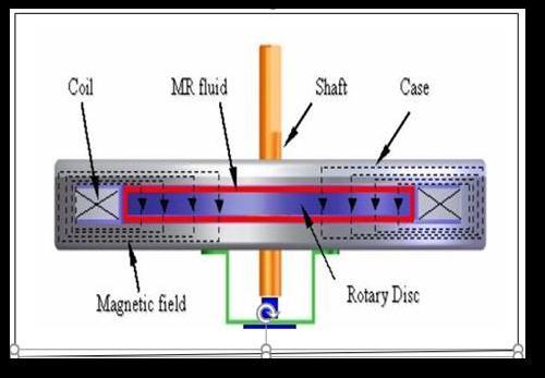
Thesteeringsystemisthevehicle'sprimaryinterfacewith the driver. The steering system has apparent challenges: accurate steering with no play is required.It should be direct and smooth, as well as small and light.Itmustalso givethedriveraperfectsenseoftheroadsurfaceandassist the wheels in returning to a straight-ahead posture. At high speeds, the power steering gear truly comes into its own in terms of safety potential. Hydraulically Assisted Re-circulatingBall Screw Steering System was one of the projects we worked on. The graph below shows the relationship between oil pressure in the steering system and steering effort used by the driver, as provided by ZF SteeringGear(Ltd)India.
Technology (IRJET) e-ISSN: 2395-0056 p-ISSN: 2395-0072
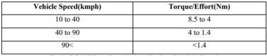
The above curve shows that when the oil pressure inthe steering system rises, the needed effort, or required torque at the steering wheel in Newton- meters, rises as well. The friction between the tires diminishes as the vehicle's speed increases. Because resistance causes an increase in oil pressure in the steering system, we can assume that as the vehicle's speed increases, the effort required to guide it reduces and vice versa. The graph shows that the effort required at high speeds, such as at orabove100kmph,isroughly1.5Nm.Accordingtodata gathered by ZF Steering Gear (Ltd) India, the effort necessary for satisfactory and comfortable vehicle steeringshouldbebetween3.5and4Nm.
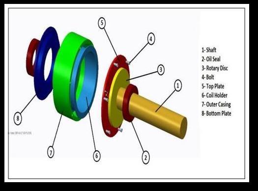
Wedevisedasteeringdamperusingmagnetorheological fluidtoaccomplishthis.Theprimarycomponentsofthe damperareasfollows: 1.CoverPlate
RotaryDisc
BackPlate
CoilHolder
HousingCover
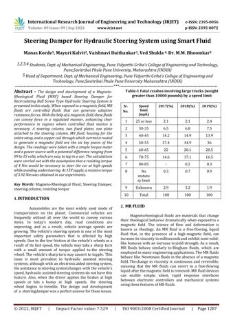
The damper's construction is described below: As illustratedinthediagram,all oftheabovecomponentsare assembledonthesteeringcolumn.
Fig- 1 :-Working principle of Steering Damper
Graph -1: Pressure of oil Vs Effort applied by the driverVolume: 09 Issue: 09 | Sep 2022 www.irjet.net
International Research Journal of Engineering and Technology (IRJET) e-ISSN: 2395-0056 p-ISSN: 2395-0072
5.
Theparametersofmagneticfield,thecurrentsupplied andthenumberofturnsinthecoilisgivenbyAmpere’s law:
Fig -2:
view of the assembly
The rotary disc is spot welded to the steering columnand rotates with it. The Cover Plate covers one side ofthe rotarydiscwhiletheBasePlatecoverstheother.Theshear gapisthespacebetweentheRotarydiscandthe two plates on either side. A coil holder wraps around the circumference of this rotary disc. The entire setup is protected by a housing cover. To preventleakage,boththe baseplateandthecoverplatehaveanoil seal on the inner diameter.TheMRfluidcanbefoundbetweentheplateson either side of the rotary disc. Because the cover plate and base are stationary, the MR fluid produces shear force on therotatingdiscasitrevolves.TheMRFluid'sviscositywill growwhenthe magnetic field is increased. The resistance to motion will grow as the viscosity increases. This, in turn, will result in the formation of resistive torque, also knownasdampingeffect.Onthebasisofthisidea,wemay developasystemforuseonavehicleinwhichthemagnetic effectvarieswithvehiclespeed,allowingfor an acceptable steering torque to be achieved as speed increases. For this reason, an ECU can be constructed that takes the vehicle's speed as an inputand outputs the appropriate voltage to the coil, resulting in varied steering torques at differentvehiclespeeds.Thiswillhelpusachieveourgoalof increasing
steeringeffortasvehiclespeedrises.
Where,
N=numberofturnsofthecoil
I=currentinthecoil(Amp.)
=magneticintensityinthefluidgap(Amp/m)
=lengthoffluidgap(m)
=magneticfieldinmildsteel(Amp/m)
=lengthofthesteelpath(m)[4]
Assuming no magnetic leakage, the magnetic induction is constant, so the relationship between the field and intensityofmagneticinductionBcanbecalculatedby,
Where,
��0=Permeabilityofvacuum=4��∗10 7(N/amp²)


����=Permeabilityofdifferentmaterials(N/amp²)
��=Magneticflux(weber)A= Effectivearea(m²)
So,thecoilcanbedesignedbasedonthefollowing equation:
Where,
����=Relativepermeabilityofmildsteel
���� =RelativepermeabilityofMRFluid[4]
Where,
International Research Journal of Engineering and Technology (IRJET) e-ISSN: 2395-0056 p-ISSN: 2395-0072
Volume: 09 Issue: 09 | Sep 2022 www.irjet.net
=Relativepermeabilityofmildsteel=1500
strengthH=20kPa
=viscosityofMRFluid=1.001(Pa-s)
=angularvelocityofsteeringcolumn=25(rad/s)


=radiusofworkinginterface(m)
=sheargap=0.002(m)
=shearstressatappliedmagneticfieldH(kpa) =correspondingyieldstressatmagneticfield A
=RelativepermeabilityofMRFluid=4.2 Now And
Hence =151.998 From(4)
Hence =151.998 From(3) HencetheproductofNoofturnsandthecurrentmust be151.998.
=innerradiusofrotarydisc=radiusof steeringcolumn=0.01279(m)
=outerradiusofrotarydisc(m)
Theresistanttorquecanbecalculatedasfollows:
Ifthereare200turnsofthecoil,thenthecurrent requiredtoproducemagneticfieldintensityof0.4Tis, 4.1 Volume of MR Fluid Required ……………..(2)
Astherequiredtorqueis2.5Nm,letusassumethat Torqueisslightlygreater(say)T=4Nm
Hence Now
Where,
=MagneticFluxDensity(Tesla)=0.4Tesla fromgraphprovidedbyFalconMRTech
=Noofturnsofcoil
=Current(Amp)
=Permeabilityofvacuum= (N/Amp²)
=Relativepermeability
=length/thicknessofpathofmagneticfield(m)
Hence ………………..(3) Where ………………..(4)
= 14.428ml
The following table shows different values of torquesfor different values of voltages as measured by a Torque meter.
Table-2 Observation Table
s = (1) Now ( = SR.NO. VOLTAGE(VOLTS) TORQUE(N-m) 1 9 1.40 2 9.5 1.62 3 10 1.82 4 10.5 1.96 5 11 2.14 6 11.5 2.38 7 12 2.59 8 12.5 2.82 9 13 3.08 10 13.5 3.32 11 14 3.55 12 14.5 3.78 13 15 3.92
Volume: 09 Issue: 09 | Sep 2022 www.irjet.net
International Research Journal of Engineering and Technology (IRJET) e-ISSN: 2395-0056 p-ISSN: 2395-0072
in a change in magnetic flux density. Similarly, changes inmagnetic flux density are caused by the thickness of thecoilholder.
The shear gap is inversely related to the amount ofshear stressproduced,andtheamountofshear stressproduced isdirectlyproportionaltotheresistivetorque,asshownin the preceding design approach. As a result, a reduction in the shear gap will result in an increase in the resisting torque.
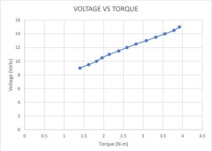
Theprecedinggraphandobservationtableshowthatwhen the voltage increases, the resistive torque increases, implying that the effort required to turn the steering wheelincreases.
MR Damper's operating and performance are influenced by a number of design criteria. Theconsequences of each oftheseparametersareexploredfurtherbelow.
Theworkinginterfaceareachangesasthediameter ofthe disc and the plates on either side changes. The working interface area is exactly related to the resisting torque produced, as seen in the preceding design technique. As a result,increasingthe0inradiioftheplatesandrotarydisc will increase the area of the working interface. The shear stress and resistant torque produced are directly proportionaltotheareaoftheworkinginterface.However, whenthediametergrows,theamountofMRFluidutilised grows as well. However, because MR Fluid is expensive, this method will become uneconomical as the radius increases.
Ourresultswereinfluencedbyalloftheabovefactors,and the surface polish of our product was up to 4 microns. Furthermore, because the rotary disc was manually soldered to the rotating shaft, it was not completely parallel. The rotary disc would have been exactly parallel to the plates on each side and there would have been no relative motion between theshaftand the rotary disc if it hadbeenanintegratedpartoftherotaryshaft.
We have concluded that a magnetorheological fluid dampercancreateresistivetorqueforthesteeringsystem based on theoretical information from many research articles and practical experiments with our model. The working surface area, electromagnet, and shear gap all have an impact on this system. Our testing results show that at a potential difference of 21V, a resisting torque of 3.92 Nm was attained. We also discovered that the amountofresistivetorqueproducedisproportionaltothe appliedvoltage.
The magnetic flux density will alter as the design ofthe electromagnetchanges.Magneticfluxdensityis
precisely
proportional to shear stress, according to the graph provided by FALCON MR TECH. As the magnetic flux densityrises,theshearstressrisesaswell, as does the resistive torque. We'll have to adjustthedesign of the electromagnet to change the magnetic flux density. The magnetic flux density will grow as thenumber of turns increases. If the coil holder material is changed, the relative permeability changes, resulting
The analytical and actual findings differ because the analytical calculations were performed under ideal conditions.Therotarydiscwasweldedtothesteeringrod inactualtestingsettings;asaresult,the rotarydisc isnot completelyparalleltotheplatesoneitherside,resultingin a non-uniform shear gap, which directly influences the resisting torque. The outcomes would have been better if ithadbeenanintegralpartofthesteeringrod.Themodel ofsteeringrodonwhichweinstalledourMRfluiddamper hada5mmplayinthedirectionoftheaxisofsteeringrod. This play, or movement in the direction of the axis of steering rod, causes movement of the rotary disc, which causes a change in shear gap, and thus has a significant impact on our test results. As a result of the above explanation, we can deduce that increasing the working contact area, increasing the magnetic fluxdensity, and decreasing the shear gap are the primarycharacteristics forgeneratingagreaterresistingtorque.
International Research Journal of Engineering and Technology (IRJET)
Volume: 09 Issue: 09 | Sep 2022 www.irjet.net
1. Jae-Hoon Lee, Changwan Han, Dongsu Ahn, JinKyoo Lee, Sang-Hu Park and Seonghun Park, “Design and Performance Evaluation of a Rotary Magnetorheological Damper for Unmanned Vehicle Suspension Systems”, The Scientific World Journal, Volume2013.
2. Deepak Baranwal, Dr. T.S. Deshmukh, “MR-Fluid Technology and its Application_A Review”, International Journal of Emerging Technology and Advanced Engineering, Volume 2, Issue 12, December 2012.
3. S. Elizabeth Premalatha, R. Chokkalingam, M. Mahendran, “Magneto Mechanical Properties ofIron Based MR Fluids”, American Journal of Polymer Science2012.
4. Gangrou Peng, “Development of MR Fluid damperfor motorcycle steering system”, University of WollongongThesiscollection,2011.
5. Saiful Amri Bin Mazlan, “The Behaviour of Magnetorheological Fluids in Squeeze Mode”,Dublin CityUniversity,August2008.
6. R.Turczyn,M.Kciuk,“Preparationandstudyofmodel magnetorheological fluids”, Department of Physical Chemistry and Technology of Polymers, Silesian University of Technology, ul. Marcina Strzody 9, 44100 Gliwice, Poland, Division of Nanocrystalline and Functional Materials and Sustainable Pro-ecological Technologies, Institute of Engineering Materials and Biomaterials, Silesian University of Technology, ul. Konarskiego18a,44100 Gliwice, Poland, received 31.01.2008; published inrevisedform01.04.2008.
7. A.G. Olabi, A. Grunwald, “Design and application of magneto-rheological fluid”, Ireland, Received 4 April 2006,accepted12October2006.
8. Bin Liu, “Development of 2- DOF Haptic Feedback Devices Working with Magneto-Rheological Fluids”, UniversityofWollongongThesisCollection,Year2006.
9. Kerem Karakoc, “Design of a Magnetorheological Brake System Based on Magnetic Circuit Optimization”,BogaziciUniversity,TURKEY,2005.
10. Seval Genç, “Synthesis and Properties of Magnetorheological (Mr) Fluids”, M.S. in Physics, BogaziciUniversity,Turkey,1994.
e-ISSN: 2395-0056 p-ISSN: 2395-0072
11. J. Wang and G. Meng, “Magnetorheological Fluid devices: principles, characteristics and applications in mechanical engineering”, State Key Laboratory of Vibration, Shock and Noise, Shanghai Jiao Tong University, People’s Republic of China and Siyuan MechatronicsInstitute,FoshanUniversity, Guangdong Province,People’sRepublicofChina.
12. Stuart W. Charles, “The Preparation of Magnetic Fluids”,DepartmentofChemistry,UniversityofWales, Bangor,GwyneddLL572UW,UK.