International Research Journal of Engineering and Technology (IRJET) e-ISSN: 2395-0056
Volume: 09 Issue: 09 | Sep 2022 www.irjet.net p-ISSN: 2395-0072
International Research Journal of Engineering and Technology (IRJET) e-ISSN: 2395-0056
Volume: 09 Issue: 09 | Sep 2022 www.irjet.net p-ISSN: 2395-0072
1,2,3 UG Scholar, Department of Mechanical Engineering, Kumaraguru college of technology, Coimbatore. 4 Assistant Professor, Department of Mechanical Engineering, Kumaraguru college of technology, Coimbatore ***
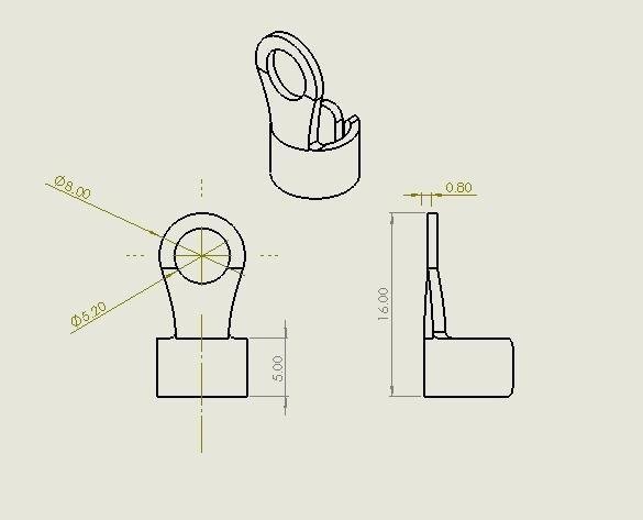
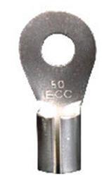
Abstract - The press tool is the custom based tool that is used to produce component in a large quantity from a sheet metal. A major part of the press tool is die, punch, punch plate, stripper, and ejector. The project work aims to reduce the production time of wire crimp connector. In the traditional method, the part is manufactured through three operations. They are blanking, forming, finishing and the three types of tools and dies are used to produce the component. In this experimental work the replacement of three types of tools and dies with the single custom made press tool and die. In a single operation, the three process is done and got the finished product as the output. The project work concluded that by implementing the custom press tool in the punching machine will increase the production as well as reduction in the cycle time. The production can be increased by three times the existing production method. Keywords: Customized press tool, die plate, sheet metal, cycle time.
Key Words: Customized press tool, die plate, sheet metal, cycle time.
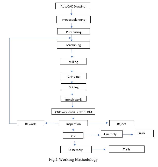
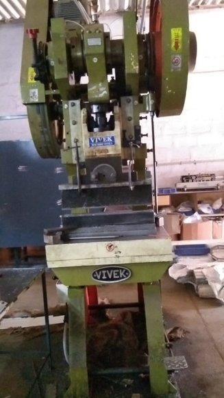
Thepunchpressworksontheprincipleofconvertingcircularmotionintolinearmotion.Themainmotordrivestheflywheelof themachine,whichgeneratespower.Thefollowingcomponentsareusedcrankshaft,rockerarm.Theconnectingrodandthe slidingblockmusthaveaplacelinearandcircularmotioncanswitch.Thereareessentiallytwomechanismsinitsdesign:oneis aballtype,andtheotherisapintype,bothofwhichtransformcircularmotionofthe sliderintolinearmotionandlinear motionisusedtoachievethenecessaryshapeandprecision,thepunchdeformsthematerialplastically.Thematerialmustfit intoapairofmoulds(uppermouldandlowermould),betweenwhichthemachineexertspressuretodeformthematerial.The reactionforcebroughtonbytheforceappliedtothematerialduringprocessingisabsorbedbythepunchmachinebody.The stamping process has the potential to be more efficient than traditional mechanical processing and create items that are impossible to create through mechanical processing through a variety of Mould applications. It has a wider range of applicationsnow.
Khosaetal.,2015.Investigatedthedesignandmanufactureofaprogressivepresstoolforachainlinkispartoftheproject work.Conveyorbeltsusechainlinks,whicharemadeofmildsteel.Thelinkhasathicknessof2mm.Aprogressivetoolisone that has multiple stations where operations are performed. The device has been designed and manufactured. The manufacturedpartsareinspectedbeforebeingassembled.Theprogressivetoolisalsoputtothetest.[1]Parmaretal.,2017 studiedthemajorobjectiveistodevelopadiewithinterchangeablepunchesanddiesandtolightenthematerialbyalteringthe materialofdiesets.Thisshouldconstantlyeliminatethelossinproductiontimeandreducesthepowerfromloadingand unloadingthesheets.Thecomponentsofthediearedesignedinthesolidworksandassembled.TheFiniteelementanalysisof eachpartofthediesetsaredonewiththesimulationpresstool.[2].Afzaletal.,2019explainedthedesignandmodellingofa progressivecampresstoolforthecomponentbladefuseholder,whichisutilizedintheprintedcircuitboardsofcars,are coveredinthisarticle.Thecomponentgeometryandmaterialspecificationsarecarefullyexaminedatthestartofthedesign andmodellingprocess.Thetooldevelopmentandmodelling,whichwasdonewiththemodellingsoftwareSolidWorks,are describedindetail.Theadvantagesanddisadvantagesofprogressivetoolscomparedtostagetoolsarealsodiscussed.[3] Shailendra,2011studyandexaminesimportantfactorsandoffersanintelligentsystemforchoosingmaterialsforpresstool componentsusedinsheetmetalproduction.Thesystempromptstheusertoenterrequiredinformationbeforeproviding intelligentmaterialselectionadviceviatheuserinterface.Dependingontheavailabilityofnewmaterialsandtechnological advancements,thesystem's knowledgebasecanbemodified.Becausetheproposedsystemcanbeimplementedona PC runningAutoCADsoftware,itslowimplementationcostmakesitaccessibletodiedesignersandtoolmakersinsmalland medium-sizedsheetmetalbusinesses.Asamplerunusinganexampleofanindustrialcomponentisusedtodemonstratethe utilityoftheproposedsystem.Duetothesystem'sinexpensiveimplementationcostanditsabilitytobeusedwithAutoCAD softwareonaPC,smallandmedium-sizedsheetmetalindustriesmayeasilyaffordtouseit.[4].Razleeetal.,2019investigated
2022, IRJET | Impact Factor value: 7.529 | ISO 9001:2008 Certified Journal | Page1251

International Research Journal of Engineering and Technology (IRJET) e-ISSN: 2395-0056
Volume: 09 Issue: 09 | Sep 2022 www.irjet.net p-ISSN: 2395-0072
andredesignthedieandstriplayoutoptimization,thestudyisconductedusingAutoCADandSolidWork.Followingthat, ABAQUS/CAE and e-fatigue are used to complete the analysis and lifecycle results for punches with various punch edge designs.Accordingtotheoreticalanalysis,punchdesignplaysasignificantroleinlifecycleanalysis.Byloweringonestagefrom sixtofivephases,stageoptimizationwasaccomplished.[5].Andure,2018developingapneumaticallyoperatedcuttingand punchingmachinewhichwillusethehelpofcompressedairtodriveashearingbladeandpunchtocarryouttheoperationson ametallicsheet.Astwooperationscanbeperformedonthesameplatform,thismachinewillprovetobecost-effectiveand timesaving in the manufacturing process. It has been noted that pneumatic equipment is less expensive than hydraulic equipment. [6]. Venkata & Rayudu, 2021 explained the project work that involves design, analysis, and manufactureof a combinationtooltoproducetabletopnamecardholder.Thecombinationoftooldonebothjobslikeblankingandbending. UsingthesoftwaretoolANSYS,thedesignandanalysisofacombinationtoolforadevelopedcomponenthavebeenvalidated. Thecomponent'squalitywasevaluatedandfoundtobewithinpredeterminedlimitationswhenthetoolwasconstructed, tested,andproducedforatrialrun.[7]Surabhietal.,2015describesandformsabasisbyaccumulatingfactorsfortoollife selection.Theinformationisbasedonanoutdatedtoolthathasbeencarefullyexamined,withmodificationsmadethatare discussedinthispaper.Inthiswork,theymodelaprogressivetoolforanarcchuteplateusingthesoftwareUNIGRAPHICS. Here,amulti-stationdiethatperformstrimmingandsplittingoffoperationssimultaneouslyisused.Ithasbeendeterminedby introducingprogressivedieforarcchuteplatesthatthetoolisverypracticalformediumbatchsizesandeffectivetouse.The toollifeis3–12laccomponentswhenutilisingatwo-steptooldie.[8].Student,2018investigatedthedefectsandRemedies. Thisprojectreportfocusesonthevariousaspectsof"PressTool."Thisreportprovidesasummaryofthedesignanalysisand overviewofa"PRESSTOOL"thatmeetsthedemandforsheetmetalcomponentmassproduction.Thejobhasbeendone graduallyandindetailforeveryanalysis.Withoutconductingthesestudies,thetoolcouldstillbebuiltandproduced,butits viabilityandeconomicsarenotguaranteed.[9].Sachin&Yathish,G,2015studiedtheseveraloperationscanbeperformedin seriesinaprogressivetoolasthestockregistersatdifferentworkstationsduringeachstrokeleadingtothedevelopmentofthe finalcomponent.Thecorrespondingprocessestocreateahandlebracketare,respectively,blanking,punching,andbending. ThepunchanddiefortheprogressivepresstoolinthisjobaremadeofD3steel,andtoensurethedesignissafe,staticanalysis usingANSYSsoftwareisthencompleted.Ithasbeenestablishedthatthestressvaluesforeachcomponentarelessthanthe actualyieldstressofthematerial.[10]
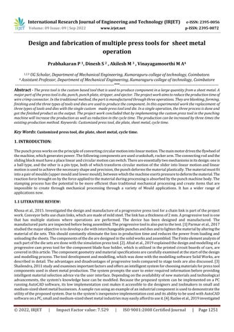
Thefirststageistochoosethecomponentthatwillbemanufacturedbythetool.Oncetheconceptofthecomponentdesignis finished,ensurethattheconceptofthetooldesignisfunctional,manufacturable,maintainable,andthatthetoolconsistently producesthedesiredtargetwithoutfail.Designingthetoolentailscreatingprecisepartdrawingsofthetoolinaccordancewith thenecessarydimensionalprecisionandtolerances.AutoCAD,adesignprogramme,wasusedtocompletethe design.All practical applications, including cutting raw materials to the required size and shape in accordance with the design's dimensionalcorrectnessandtolerances,areapartoftoolproduction.Theproducedcomponentswillbeputtogetherand inspected.Try-outwillbecompletedaftertheassemblyhasbeenconfirmed. Themanufacturedcomponent'sdimensional accuracy will be checked. If the dimensions do not meet the required accuracy, the Tool must be reworked or modified, requiring secondary operations, and another test will be conducted. The tool will be set up for mass production and the necessarymaintenanceworkwillbecarriedoutperiodicallyifthetrialcomponentmeetstherequisitedimensionalaccuracy andtolerances.
International Research Journal of Engineering and Technology (IRJET) e-ISSN: 2395-0056
Volume: 09 Issue: 09 | Sep 2022 www.irjet.net p-ISSN: 2395-0072
Bottomplate:
BolsterplateandDieshoearesomenamesforit.ItiskeptinasoftstateandisconstructedofeitherMSorcastiron.The bottomplatetemporarilyincreaseslift.offersaccesstothediesandenoughspaceforthetooltobesupportedbythepressbed. Thebottommayhaveholes.platethatmakesitpossiblefortheblanktodetachfromthetool.
BackupplateorThrustplate:
ItisconstructedofOHNSorcase-hardenedsteelthathasbeenhardenedandtemperedtobetween55and58HRC.If case-hardeningsteelwasused,thedepthofCarburizinginthecasingmustrangefrom0.8to1.3mm.Whilewhencutting,the punchprovidesupwardpressure.thrust,attemptingtonotchthetopplate,leadingtointhevariationofpuncheslevel.Punch shouldthereforebesupportedbyatokeepitfromdiggingintothetopplate,aharderplatewasused.Forthisreason,thisplate isalsoknownasapunchretainerplate.thatitkeepsthepunchinplacewhiletheprocedureisbeingdone.
International Research Journal of Engineering and Technology (IRJET) e-ISSN: 2395-0056
Volume: 09 Issue: 09 | Sep 2022 www.irjet.net p-ISSN: 2395-0072
Dieplate:
Dieplates,whicharefemalecomponentsoftoolsmanufacturedofhardenedandtemperedHCHCRmaterialforcutting operationsTemperedtoanHRCof60–62.Regardingnon-cuttingoperations,OHNSTo55–58HRC,thematerialisutilised, hardened,andtempered.Itgivesthecomponentwithanexteriorshape.
Stripperplate:
It's constructed of MS (St-42) material. It is typically kept in a soft state, however some OHNS-made tools have it hardenedandtemperedto55–58HRC.Theplate'sprimarygoalistoremovematerialfromthepuncheswitheachstroke.The stripperwillalsobeemployedtoholdthestriptautandhorizontalwhileitisbeingworkedon,aswellastodirectpunches.In some cases, it might even steer the stock strip. They are classified into two groups such as fixed strippers and traveling strippers.
Punchholderplate:
It will be in a soft condition and made of MS (St-42). Typically, the punch is inserted using a mild key fit (H7/k6). Sometimesakeyoradowelneedstobeplacedinthepunchholdertostoptheprofiledpunchesfromrotating.
Topplate:
ItisasoftplatecomposedofMS(St-42),andasopposedtoallotherplatessavethebottomplate,itwillbelargeroverall. Toloadingonthepress,thisplateissecuredtothepresstool'stopunit.Thetoolshankisscrewedintothisplate,whichneeds tobethickenoughtoavoidbending.
MSmakesuptheobject.Holdingtheshankfirmlyintheramholeallowsthetooltobelocatedandsecuredtothepress ram.Thediameterofthepressramborewhereagiventoolisdesignedtoinstalldeterminesthetool'sshank.Standardized shanksareavailableforvariouspresses.
Thesheetmetalpunchingmachinesusepunchesthatcutthroughthesheetmetal,andthedies,whichareplacedontheopposite sideofthemetalpiece,serveasasupporttoensurethatthemetaldoesn'tbreakwhilealsoassistingthepunchesinproducing exactanderror-freeholes

International Research Journal of Engineering and Technology (IRJET) e-ISSN: 2395-0056
Volume: 09 Issue: 09 | Sep 2022 www.irjet.net p-ISSN: 2395-0072
CUTTINGCLEARANCEPERSIDE
Cuttingclearanceisthattheintentionalgapprovidedbetweenthesidesofapunchanddie.
Cuttingclearance(cc)=C*S*√(σ)/10)
Where, C=Constant=0.01
S=SheetThickness=1mm
TMAX=ShearStrength=130N/mm2 Cc=0.01x1x√(210/10)
CUTTING Clearance Cc= 0.04mm/side.
Cuttingforceiswhichmustactonthestockmaterialtochoptheblankorslug.Thisdeterminesthecapacityofthepresstobe usedfortool.
CuttingForce(Fc)=L*T*σwhere, L=TotalCutLength=215mmT=SheetThickness=1mm,ShearStrength(σ)=172.36 N/mm2
Fc=215x1x172.36, Cutting force = 37057.4 N
Itistheforcerequiredtobendtheedgesoftheblank,andthereforethebendingassociatedinthelancingoperation. BendingForceFB=0.33*S*U*W*t^2/L
Where,W=WidthofStockMaterial
L=Span=DieRadius+PunchRadius+C C=DieClearance
T=SheetThickness
Su=Ultimatelastingness(Kg/mm2)
PadForceFP=0.5FB
TotalloadrequiredFN=FB+FP=1.5
LoadrequiredforonebendingFB=0.33×210×100×1^2/1+2 =2310N
Loadrequiredfor2bendingoperations=2×2310=4620N
TotalLoadrequiredfor2bendingoperations=1.5x4620=6930N Forcerequiredtoatleastonesidebendinginlancingoperation FB=0.33×210×24×1^2/1+2+1 =4158N
Total Bending load = 4158N
Strippingforceisthattheforcerequiredtostriptheblankfromthepunches.it'sthesumofthecuttingforceandthestripping force.it'snormallyexpressedintons.
Strippingforce=10-20%ofcuttingforce Consider20%ofcuttingforce
Strippingforce=20*37057.4/100
Stripping force= 7411.48 N
Itisthesumofthecuttingforce,bendingforceandthereforethestrippingforce.
PressForce=Addingofallforces =37057.4+4158+7411.48
Press Force = 48626.88 N
Presstonnage=1.3xpressforce
2022, IRJET | Impact Factor value: 7.529 | ISO 9001:2008 Certified Journal
International Research Journal of Engineering and Technology (IRJET) e-ISSN: 2395-0056
Volume: 09 Issue: 09 | Sep 2022 www.irjet.net p-ISSN: 2395-0072
=1.3x48626.88 =63214,944N Press tonnage 7 tonnes.
Thicknessofdieplate(Td)
Table No. 3
Thicknessofdieplate=3√Pressforce= 3√48626.88
Thicknessofdieplate=36.49mmButbasedupon thewidthofbendrequiredthethicknessareoften takenas20mm.
Thicknessofbottomplate
Thicknessoftopplate
Thicknessofthrustplate
Thicknessofpunchholderplate
Thicknessofstripperplate
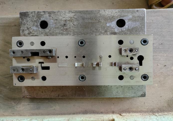
Fig.5Assembleddie(Topview)
Thicknessofbottomplate=2xTd=2x20Thickness ofbottomplate=40mm
Thicknessoftopplate=1.5xTd=1.5x20 Thickness of top plate =30mm However, considering the washer's thickness and stroke length. The thickness of Top plate is often takenas32mm.
Thicknessofthrustplate=8mm
Thicknessofpunchholderplate=0.75x28= 20mm
Thicknessofstripperplate=0.75x28=20mm
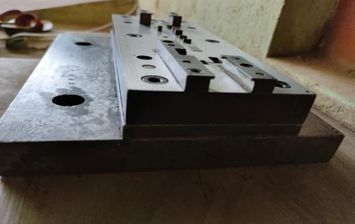
Fig.6Assembleddie(Sideview)
Thefig.5showsthetopviewofassembleddieandFig.6showsthesideviewofassembleddie.Inthisinvestigation,startwith thehalfoftheblankingoperationandfoldingoperationiscompletedupto90degrees.Eachendofthesheetgotmergedwith oneanother.Atthefinalstage,anotherhalfofblankingprocessisdoneandtheachievedcompleteproduct.
International Research Journal of Engineering and Technology (IRJET) e-ISSN: 2395-0056
Volume: 09 Issue: 09 | Sep 2022 www.irjet.net p-ISSN: 2395-0072
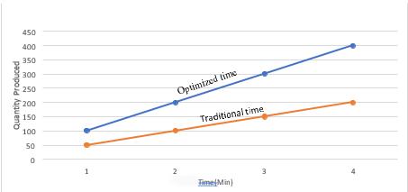
Thegraphrepresentsthetimeandproductionofbothtraditionalmethodandinnovativemethod.Thebluelineclearly representssignificantriseinproductivitycomparedtotraditionalmethod.
Inthisexperimentalinvestigation,thedesignofacombinationtoolwasmanufactured,andtesting.Thesequenceofoperations suchasblankingandfoldingthequalityofthecomponentinspectedwiththeinstruments,nowtheToolisreadyformass productionofthegivencomponent
1. Khosa,P.,Hiremath,C.,Odugoudar,B.,Haveri,S.,Mechanical,B.,&Automation,B.(2015).DesignandManufacturingof ProgressivePressTool.InternationalJournalofAdvancesinMechanicalandCivilEngineering,2,20.
2. Parmar, M. A., Patel, D., Patel, K., Patel, B., & Patel, M. (2017). A Review on Process of Press Tool Design and its Manufacturing.ImperialJournalofInterdisciplinaryResearch(IJIR,3(3),1640–1643.
3. Afzal,A.,Sirajuddin,M.,AbdulRazak,R.K.,Chethan,K.M.,&Avinash.(2019).ModellingandAnalysisofaProgressive CamToolforBladeFuseHolder:ACase Study.JournalofPhysics:ConferenceSeries,1355(1).https://doi.org/10.1088/17426596/1355/1/012038
4. Shailendra, K. (2011). An Intelligent System for Selection of Materials for Press Tool Components. An Intelligent SystemforSelectionofMaterialsforPressToolComponents,Ii.
5. Razlee,A.,Kadir,A.,Zaki,M.,Abdul,B.,Othman,N.,&Izham,M.(2019).DesignandAnalysisofStageProgressiveDie foraSheetMetalComponent.InternationalJournal of Recent Technology and Engineering, 8(4), 834–841.https://doi.org/10.35940/ijrte.d7417.118419
6. Andure,P.M.W.(2018).DesignandFabricationofPneumaticSheetMetalCuttingMachine.InternationalJournalfor Research in Applied Science and Engineering Technology, 6(1), 1598–1602. https://doi.org/10.22214/ijraset.2018.1245
7. Venkata, P., & Rayudu, S. (2021). Design of a combination tool. February, 0–9. https://doi.org/10.35940/ijitee.xxxxx.xxxxxx
8. Surabhi,M.,Bagul,S.,Dhadiwal,N.S.,&Chopda,J.R.(2015).InternationalJournalofModernTrendsinEngineering andResearchExperimentalStudyforImprovementofPressToolLifeandComponentAccuracy.2349,2–4.
9. Student,M.T.(2018).DesignandAnalysisofPressToolAssembly.6(2),130–135.
10. Sachin, G., & Yathish, G, A. (2015). Design Analysis and Overview of Press Tool With its Defects and Remedies. InternationalJournalofEngineeringTechnology,ManagementandAppliedSciences,3(March),1–10.
2022, IRJET | Impact Factor value: 7.529 | ISO 9001:2008 Certified Journal |