International Research Journal of Engineering and Technology (IRJET) e-ISSN: 2395-0056

Volume: 09 Issue: 09 | Sep 2022 www.irjet.net p-ISSN: 2395-0072
International Research Journal of Engineering and Technology (IRJET) e-ISSN: 2395-0056
Volume: 09 Issue: 09 | Sep 2022 www.irjet.net p-ISSN: 2395-0072
***
Abstract -This work is carried out on a parabolic leaf spring of a TATA ACE mini loader truck, which has a loading capacity of 750kg. The modelling of the parabolic leaf spring has been done in Creo-2.0. And for finite element analysis the parabolic leaf spring model was imported in the static structural analysis workbench of ANSYS-14 software. Life of spring, damage ,fatigue safety factor,fatigue sensitivity of the parabolic leaf spring are the output parameters of this fatigue analysis. parabolic leaf spring is a very important element in automobile suspension system, To overcome of this work, steel parabolic leaf spring is replaced with the composite material parabolicleaf spring. use of composite material theweightofthespringdecreases withoutanincrease in costandadecreaseinqualityandreliability.
Keywords: composite parabolic leaf spring,weight reduction,fatiguelife,FEA.
1.1
This work is carried out in two parts, the first part deals with geometric CAD modeling of a parabolic composite leaf spring with construction details, and the second part deals with the analysis of the parabolic leaf spring, by using ANSYS-14 software. ANSYS software is used for general purpose finite element analysis and for numericallysolvingmechanicalproblems.HereANSYS-14 is used for analyzing the performance of conventional steel EN45 and composite parabolic leaf spring. Leaf spring is modeled in Pro-Engineering creo-2.0 software and it is imported in ANSYS- 14. The conventional steel parabolic leaf spring and the composite parabolic leaf springwereanalyzedundersimilarloadingandboundary conditions using ANSYS-14 software and the results are presented. Static analysis determines the safe stress and corresponding payload of the parabolic leaf spring and also studies the behavior of structures under practical conditions.Thepresentworkattemptstoanalyzethesafe load of the parabolic leaf spring. Maximum displacement, equivalent stress, strain energy, maximum principle stresses,andweightoftheassemblyaretheoutputtargets ofthisanalysisforcomparisonandvalidationofthework. For fatigue analysis, the S-N approach is used to predict
thefatiguelifeanddamageofconventionalsteelparabolic leafspringsandcompositeparabolicleafsprings.
Parabolic leaf springs are the components of the suspension system, they perform isolation tasks in transferring vibration due to road irregularities to the driver’s body. Increasing competition and innovations in theautomobilesectortendtomodifytheexistingproducts andreplaceoldproductswithnewandadvancedmaterial products, more efforts are taken in order to increase the comfort ofusers andimprovethesuspensionsystem,and hence many modifications have taken place over time. Inventions of parabolic leaf springs and the use of composite materials, for these springs are some of the latest modifications in the suspension system. The main advantages of parabolic leaf springs are that they are lighter, cheaper, and have better fatigue life. And they isolate more noise. CAE tools are widely used in the automobile industry for modeling and analysis of automobileparts.
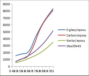
For achieving the objective of the research work a flow chart is prepared which shows various steps taken in to consideration.
ReverseEngineering
(TotakedimensionfromtheexistingPLS)
CADModelGeneration (FromCreoparametric2.0)
FatigueAnalysis(WithConventionalSteeland CompositematerialinANSYS-14)
life,damage,safetyfactorandfatigue sensitivity
International Research Journal of Engineering and Technology (IRJET) e-ISSN: 2395-0056
Volume: 09 Issue: 09 | Sep 2022 www.irjet.net p-ISSN: 2395-0072
In this simulation, the Goodman approach, Soderberg’s theory,Gerber’stheory,andmeanstresscurveshavebeen used.Thematerialthathasbeenusedforthesimulationof the parabolic leaf spring is conventional steel EN45 and composite material (E-glass/epoxy, carbon/epoxy, Kevlar/epoxy). The results were obtained using ANSYS14 software. The results are compared and the theory whichgivesthelowestvalueoflifeandthehighestvalueis chosen to be best in the analysis of steel EN45 and compositeparabolicleafspringsLoadingdataischosenas history data of SAE transmission and is applied. Life data analysis: This is carried out by applying a load of 500 to 5600N and the analysis is carried out by the abovementioned four approaches. Goodman’s and Gerber’s approach: Using Gerber’s theory the life data obtained is similar to Goodman’s theory. Mean stress theory approach: Using mean stress curves, this theory is not preferred for the life data analysis of the parabolic leaf springs.
Conventional steel EN45 parabolic leaf spring and composite parabolic leaf spring (E-glass/epoxy, carbon/epoxy, Kevlar/epoxy) are modeled with constant widthandvaryingthicknessdesign.
1. The constraints parameter i.e. dimensions and boundary condition of steel parabolic leaf springs is the sameasthatofcompositeparabolicleafsprings.
2.Fatigue life prediction of parabolicleaf spring based on finiteelementanalysisusingStresslifeapproach.
Stress-lifeDataOptions/FeaturesinANSYS-14
Afatigueanalysiscanbeseparatedinto3areas:materials, analysis, and results evaluation. Each area will be discussedinmoredetailbelow.
A large part of a fatigue analysis is getting an accurate descriptionofthefatiguematerialproperties.Sincefatigue issoempirical,samplefatiguecurvesareincludedonlyfor structural steel. These properties are included as a guide only with intent for the user to provide his own fatigue data for more accurate analysis. In the case of assemblies withdifferentmaterials,eachpartwilluseitsownfatigue materialpropertiesjustasitusesitsownstaticproperties (likemodulusofelasticity).
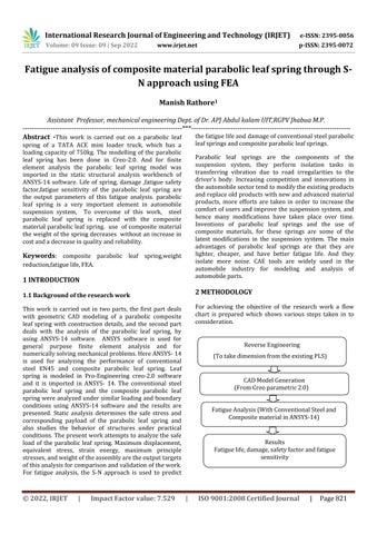
Fatigue results are often added before or after a stress solution has been performed. to make fatigue results, a fatiguetoolmustfirstbeinsertedintothetree.thiswillbe done through the solution toolbar or through context menus. the small print view of the fatigue tool is used to define the various aspects of a fatigue analysis such as loadingtype,handlingofmeanstresseffects,andmore.As seen in Figure -3.2, a graphical representation of the loading and mean stress effects are displayed when a fatigue tool is chosen. this will be very useful to help a noviceunderstandthefatigueloadingandpossibleeffects ofmeanstress.
Figure 3.1 is a screen shot showing a user editing fatigue data in ANSYS
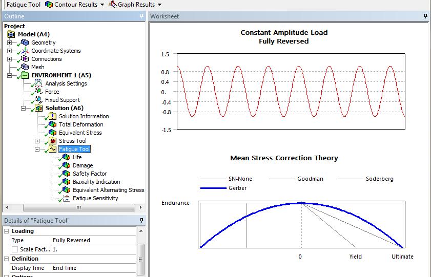
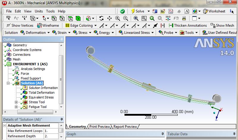
Figure- 3.2show loading type and handling of mean stress effects
Several results for evaluating fatigue analysis are available, Outputs include fatigue life, damage, factor of safety,fatigue sensitivity, each output will now be described indetail.
International Research Journal of Engineering and Technology (IRJET) e-ISSN: 2395-0056
Volume: 09 Issue: 09 | Sep 2022 www.irjet.net p-ISSN: 2395-0072
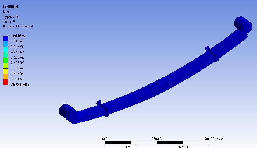
The data obtained from the analysis work is used to generate the fatigue strength factor vs. the S-N diagram. Fatigue strength is an expression used to describe a propertyofmaterial,thestressatwhichfailureoccursfor a given number of cycles is the fatigue strength. Fig-4.1 shows the life cycle of the composites and steelEN45 material at 5600N for different-different fatigue strength factors. It is observed that the fatigue life of all parabolic leaf spring materials is low when the fatigue strength factor value is low. The life cycle of the parabolic leaf spring increased gradually up to a fatigue strength factor is0.65,whenthefatiguestrengthfactorincreasesbeyond 0.65 the life cycle of E-glass/epoxy and carbon/epoxy increased at a high rate as compared to steelEN45. The maximum life of Kevlar/epoxy, steelEN45, carbon/epoxy, E-glass/epoxy at 5600N and fatigue strength factor value is 1 life is 3516, 5163, 8155, 8365 respectively. And minimum life occurs in part no. 8 of the parabolic leaf spring.
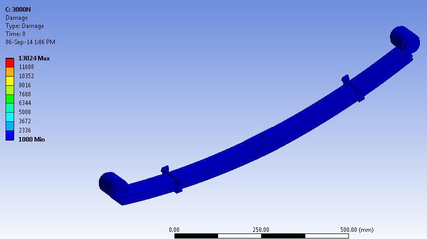
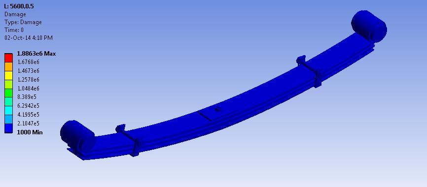
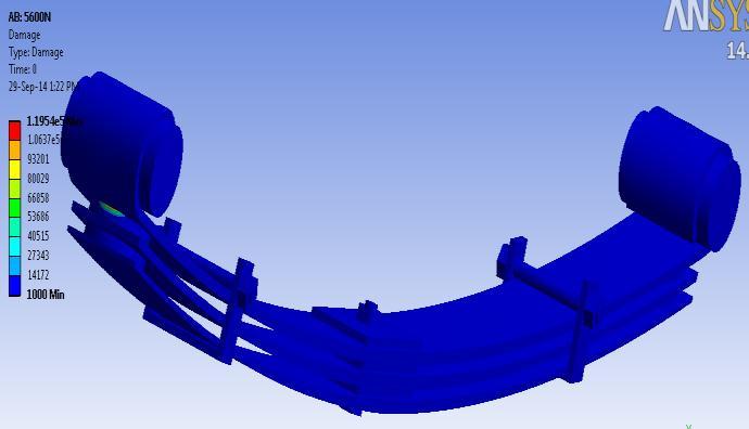
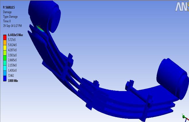
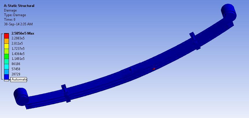
Adamage test fortheparabolicleafspringhas beendone usingtheANSYS-14fatiguetool,fullyreversedload5600N is applied, and mean stress theories are also used. The Goodman theory is often a good choice for brittle materialswiththeGerbertheoryusuallyagoodchoicefor ductilematerials.FatigueDamagemaybeacontourplotof thefatiguedamageatagivendesignlife.Fatiguedamageis defined because the design lifeis divided by the available life. This result could also be scoped. The default design life could also be set through the Control Panel. For Fatigue Damage, values greater than1indicate failure before the planning life is reached. the utmost damage of E-glass/epoxy, carbon/epoxy, Kevlar/epoxy, steelEN45 at fatigue strength factor is 0.5 is 6.4416e5, 7.8490e5, 1.8863e6, 1.3654e6 respectively. The results obtained 0.5 and1fatiguestrengthfactorisshownbelow
International Research Journal of Engineering and Technology (IRJET) e-ISSN: 2395-0056
Volume: 09 Issue: 09 | Sep 2022 www.irjet.net p-ISSN: 2395-0072
Fig.4.2showsfatiguedamageofe-glass/epoxyat5600N fatiguestrengthfactoris0.5
Fig.4.6showsfatiguedamageofkevlar/epoxyat5600N fatiguestrengthfactoris0.5
Fig.4.3showsfatiguedamageofe-glass/epoxyat5600N fatiguestrengthfactoris1
Fig.4.7showsfatiguedamageofkevlar/epoxyat5600N fatiguestrengthfactoris1
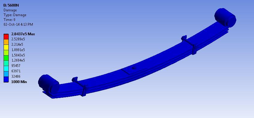
Fig.4.4showsfatiguedamageofcarbon/epoxyat5600N fatiguestrengthfactoris1
Fig.4.8showsfatiguedamageofsteelEN45at5600N fatiguestrengthfactoris0.5
Fig.4.5showsfatiguedamageofcarbon/epoxyat5600N fatiguestrengthis0.5
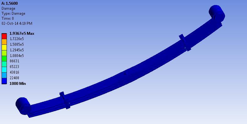
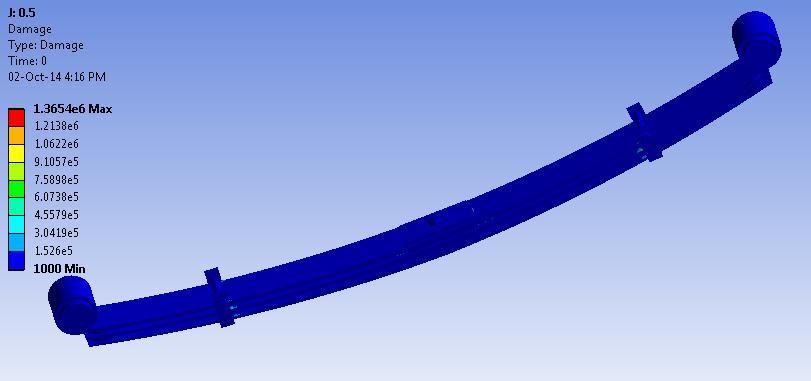
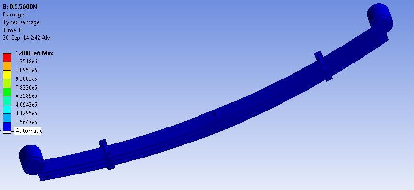
Fig.4.9showsfatiguedamageofsteelEN45at5600N fatiguestrengthfactoris1
International Research Journal of Engineering and Technology (IRJET) e-ISSN: 2395-0056
Volume: 09 Issue: 09 | Sep 2022 www.irjet.net p-ISSN: 2395-0072
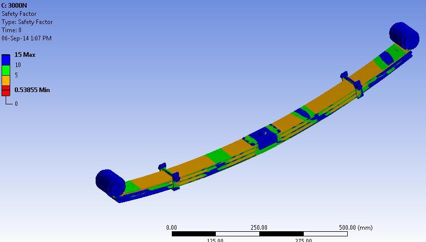
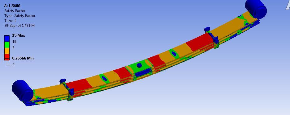
Fatigue Safety Factor is a contour plot of the factor of safety with respect to a fatigue failure at a given design life. The maximum Factor of Safety displayed is 15 like damage and life. Safety factor is a term that describes the structure capacity of a system beyond the expected loads and actual loads. The safety factor test is also performed usingANSYS-14,forfatiguestrengthfactorof0.5to1.The results shows that the safety factor of the parabolic leaf spring made up of E-glass/epoxy, carbon/epoxy, Kevlar/epoxy, steel EN45 is more than oneand thisvalue indicatedthattheparabolicleafspringissafeasthevalue is less than one indicate failure before design life is reached.The results are shown below obtained when fatiguestrengthfactor0.5and1.
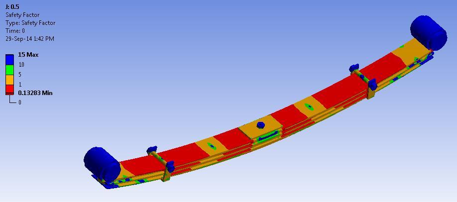
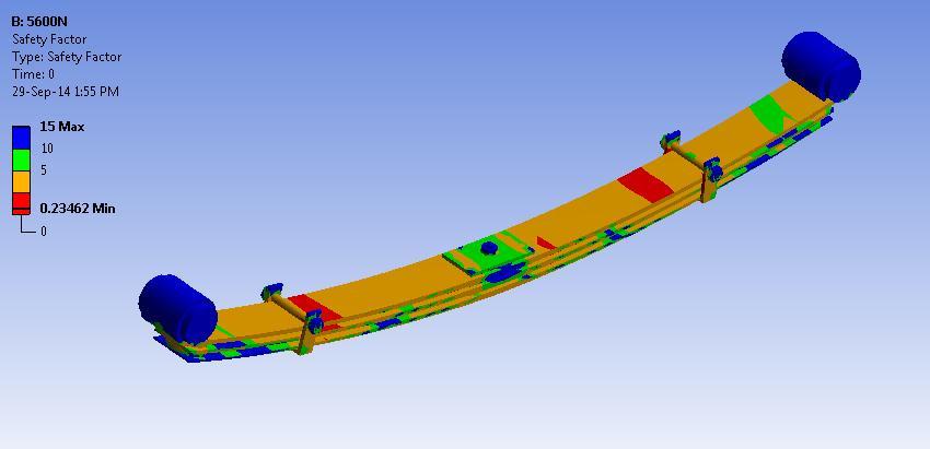
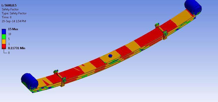
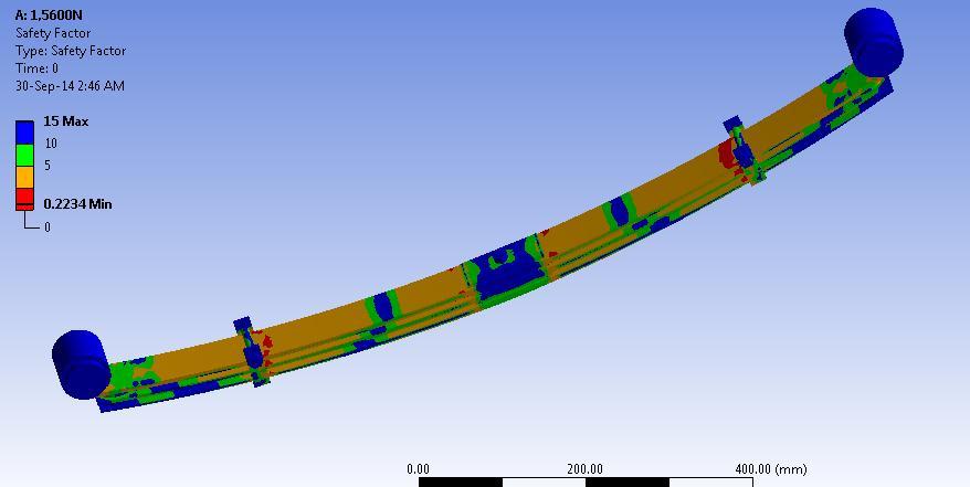
Fig.4.13showsfatigueSFofcarbon/epoxyat5600N fatiguestrengthis1
Fig.4.10showsfatigueSFofe-glass/epoxyat5600N fatiguestrengthis0.5
Fig.4.14showsfatigueSFofkevlar/epoxyat5600Nfatigue strengthis0.5
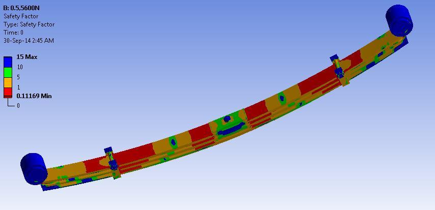
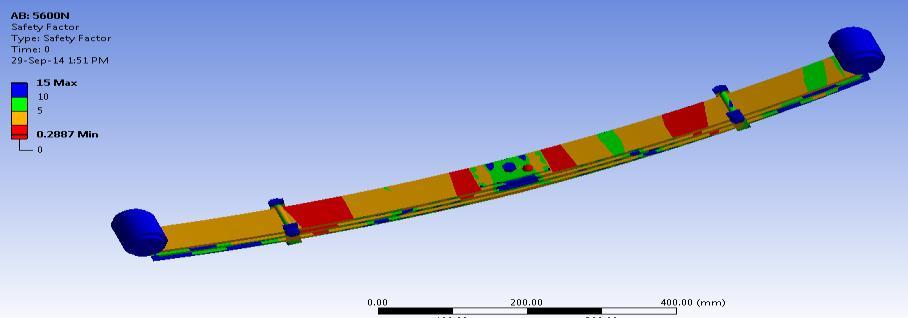
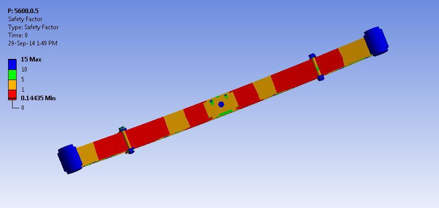
Fig.4.11showsfatigueSFofe-glass/epoxyat5600N fatiguestrengthis1
Fig.4.15showsfatigueSFofkevlar/epoxyat5600N fatiguestrengthis1
Fig.4.12showsfatigueSFofcarbon/epoxyat5600N fatiguestrengthis0.5
Fig.4.16showsfatigueSFofsteelEN45at5600Nfatigue strengthis0.5
International Research Journal of Engineering and Technology (IRJET) e-ISSN: 2395-0056
Volume: 09 Issue: 09 | Sep 2022 www.irjet.net p-ISSN: 2395-0072
Fig.4.17showsfatigueSFofsteelEN45at5600Nfatigue strengthis1
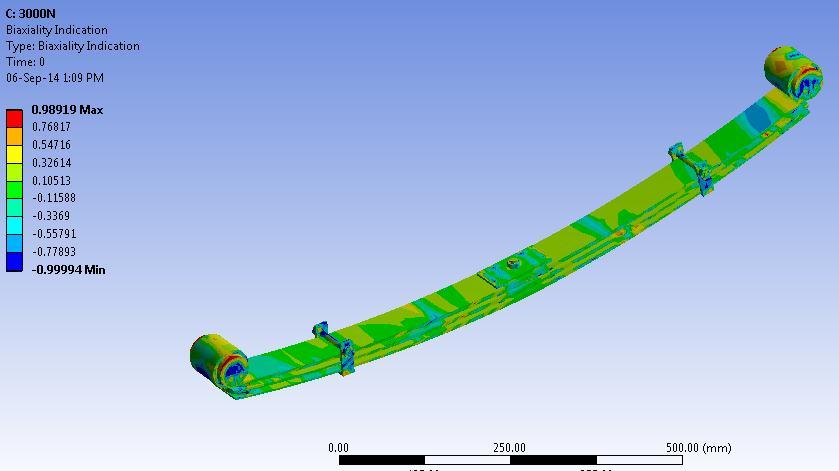
Fatigue Sensitivity shows a function of the loading vs available life at the critical location on the parabolic leaf springmodel
This result could also be scoped. Sensitivity could also be foundforlife,damage,orfactorofsafety.Theusermayset the amount of fill points as well as the load variation limits. for instance , the user might need to see the sensitivityofthemodel’slifeiftheFEloadwas50%ofthe current load up to if the load 150% of the current load. a worth of 100% corresponds to the life at the current loading on the model. Negative variations are allowed so as to see the effects of a possible negative mean stress if theloadingisnottotallyreversed.Linear,Log-X,Log-Y,or Log-Logscalingareoftenchosenforchartdisplay.Default valuesforthesensitivityoptionscouldalsobesetthrough theControlPanel.
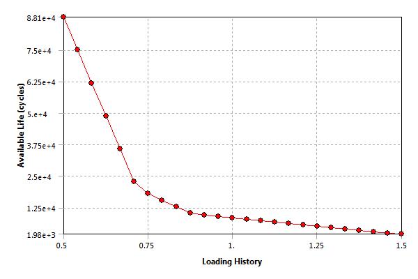
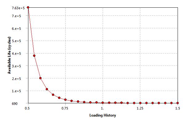
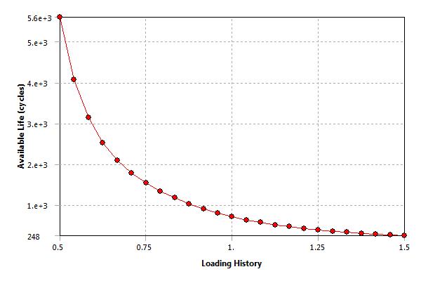
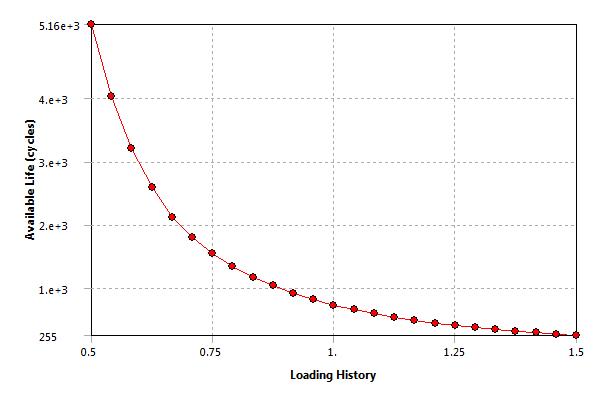
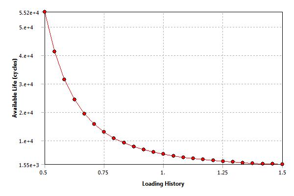
Fig-4.19showsthevariationoflifecyclee-glass/epoxyat 5600Nandstrengthfactoris0.5
Fig-4.18showsthevariationoflifecyclee-glass/epoxyat 5600Nandstrengthfactoris1
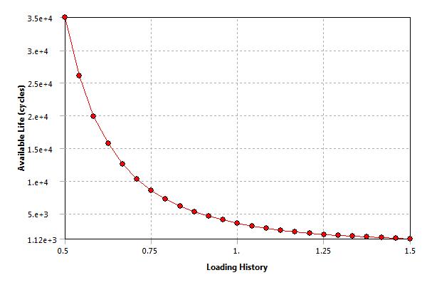
Fig-4.20showsthevariationoflifecyclecarbon/epoxyat 5600Nandstrengthfactoris0.5
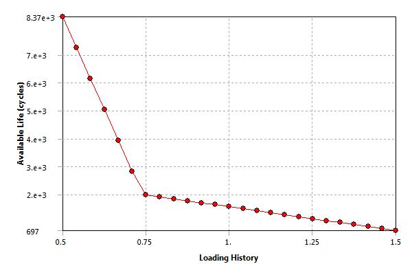
Fig-4.21showsthevariationoflifecyclecarbon/epoxyat 5600Nandstrengthfactoris1
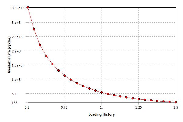
Fig-4.22showsthevariationoflifecyclekevlar/epoxyat 5600Nandstrengthfactoris0.5
International Research Journal of Engineering and Technology (IRJET) e-ISSN: 2395-0056
Volume: 09 Issue: 09 | Sep 2022 www.irjet.net p-ISSN: 2395-0072
Fig-4.23showsthevariationoflifecyclekevlar/epoxyat 5600Nandstrengthfactoris1
springs is carried with four approaches, Gerber and Goodman'sapproachisfoundouttogivebetterresultsfor the analysis of life data for parabolic leaf springs. According to the total life approach, the fatigue life of EGlassEpoxycompositeparabolicleafspringishigherthan that of steel EN45 parabolic leaf spring. This study will help to understand the behavior of the parabolic leaf spring and give information for the manufacturer to improve thefatigue life of theleafspringusingCAE tools. It can help to reduce costs and time in the research and development of the new product. Finite element method using CAE tool like ANSYS-14 Workbench prove the reliability of the validation methods based only on simulation, thereby saving time, This work will help to understand linear static behavior of the composite parabolic leaf spring and simulation data for the researcherstoimprovethefatiguelifeoftheparabolicleaf springusingComputerAidedEngineeringtool.
After carrying out the present research work, it is found that the following things can be added as an extension to thiswork-
Fig-4.24showsthevariationoflifecyclesteelEN45at 5600Nandstrengthfactoris0.5
1.Asanalysisofcomposite parabolicleaf spring andsteel EN45 parabolic leaf spring is validated by the analytical results, so one can validate with the manufacturing of actual prototype of composite and steel EN45 parabolic leaf spring by testing on the universal testing machine(UTM).
2. As this analysis is under static load conditions, so one can go for the analysis of composite and steel EN45 parabolicleafspringsunderdynamicloadingconditions.
3.Vibrationanalysisofparabolicleafsprings.
4.Experimentalprocedureisalsousedforperformingand obtaininggoodresults.
Fig-4.25showsthevariationoflifecyclee-glass/epoxyat 5600Nandstrengthfactoris1
5 conclusion and future scope
Fatigue analysis analyzed using Fatigue Tool predicting CAE results in terms of Fatigue life, Fatigue Sensitivity, Fatigue Damage, and Fatigue Safety factor. Using the constant amplitude loading and stress life approach, the fatiguedamageandlifeofthespringhavebeenpredicted. Fromthedamagecontour,thehighestdamagevalueisan acceptablerange.Thefatigueanalysisoftheparabolicleaf
1.Rajendran 1. Vijayarangan S. "Optimal Design of a Compote Leaf Spring using the genetic algorithms”computer and structures 79pp 11211129[2001].
2.DoshiNP.IngoleNK"AnalysisandModification ofLeaf Spring of Tractor Trailer Using Analytical and Finite Element Method “international Journal of modern EngineeringResearch(IJMER)pp719-722(2002)
3.MahmoodM.S.DavoodR.“Analysisandoptimizationofa composite leaf spring Composite Structures 60 pp 317325(2003)
2022, IRJET | Impact Factor value: 7.529 | ISO 9001:2008 Certified Journal | Page827
International Research Journal of Engineering and Technology (IRJET) e-ISSN: 2395-0056 Volume: 09 Issue: 09 | Sep 2022 www.irjet.net p-ISSN: 2395-0072
4.Shiva S. Vijayarangan "Mono Composite Leaf Spring for Light Weight Vehicle Design End Joint. Analysis and TestingMaterialScienceVol12,No.3(2006).
5.Rahman. M. A. Rahman S And Hossain A. H. "Large Deflection Analysis of Cantilever Beams with an Opening" International Journal of Applied Mechanics and Engineering,PolandVol12(1),pp.169-181(2007).
6.6.Hou J.P. Cherruault J.Y. "Evolution of the eye end design of a composite leaf spring for heavy axle loads sciencedirectCompositeStructures78(2007)pp351-358 (2007).
7.Patunkar M.M., Dolas D.R., "Modeling and Analysis of CompositeLeafSpringundertheStaticLoadConditionby using FEA" International Journal of Mechanical and IndustrialEngineering,Vol.1(2011)
2022, IRJET | Impact Factor value: 7.529 | ISO 9001:2008 Certified Journal