International Research Journal of Engineering and Technology (IRJET) e-ISSN: 2395-0056

Volume: 09 Issue: 09 | Sep 2022 www.irjet.net p-ISSN: 2395-0072
International Research Journal of Engineering and Technology (IRJET) e-ISSN: 2395-0056
Volume: 09 Issue: 09 | Sep 2022 www.irjet.net p-ISSN: 2395-0072
1
4
6
1Student, Dept. of Mechanical Engineering, Imperial College of Engineering and Research, Pune, India 2, 4Student, Dept. of Instrumentation Engineering, Padm. Vasantraodada Patil Institute of Technology, Sangli, India 3,5Student, Dept. of Agriculture Engineering, Dr. D. Y. Patil College of Agricultural Engineering and Technology, Talsande, India
6Student, Department of Mechanical Engineering, PVPIT, Padm. Vasantraodada Patil Institute of Technology, Sangli, India ***
Abstract - Additive manufacturing technologies are in high demand and are transforming the globe. To date, all marketedAM machinesadopta layer-based method, with themaindifferencesbeingthematerialsthatmaybeused, howthelayersareformed,andhowthelayersareattached to one other. However, additive manufacturing is mostly limited to polymers, which have a lower strength-to-size ratio.Polymercannotcreateheavystructuresduetoitslow structural stiffness. Because certain polymers cannot be recycled,whileallmetalscan,disposalbecomesaconcern. As a result, introducing another material is critical. The notionofmerginggraphenewithessentialtechnologieswill certainly result in a product with great strength and electricalconductivity.Manufacturingelectricalcircuitsisa difficult operation. Manufacturing each and every microscopic element of an electrical circuit is a timeconsumingprocedure.Theresearchisprimarilyconcerned withmergingAdditiveManufacturingwithGrapheneinkto make PCB. An external attachment is created in order to achievethepurpose.
Key Words: Graphene Extraction, AM (Additive Manufacturing),3DPrinting,GrapheneInk,Electrochemical exfoliation.
Traditional manufacturing in the machining field mainly refers to the four leading subtracting manufacturing methods:injectionmoulding,CNCmachining,plasticjoining, and plastic forming. CNC machining, also known as Computer Numerical Control machining, is a popular manufacturingmethodinwhichpre-programmedcomputer softwarecontrolsthemotionsofindustrialmachineryand tools. CNC machining is highly helpful and practical for executing complicated 3D cutting jobs that, with the right CNC equipment, may be completed in a single set of instructions.
Typically,traditionalmanufacturingprocessesneedseveral production phases, each requiring the use of a distinct
equipment to complete the task. Other manufacturing proceduresnecessitatearigorousandextensiveexamination of the component geometry to identify things like the sequenceinwhichdistinctfeaturescanbeproduced;what equipmentandprocessesmustbeemployed;andwhatextra featuresmaybenecessarytocompletethepart.Incontrast, AMrequiresonlyafewbasicdimensionalinformationanda rudimentarygraspofhowtheAMmachineworksandthe materialsusedtomaketheitem.
The most significant advantage is that this sort of manufacturingmaycreateintricategeometriesthatwould be extremely difficult to produce using traditional productionprocedures.Theseintricategeometriescreated byadditivemanufacturingareusuallylighterandstronger thantheirconventionalequivalents.MakingapartinanAM machinemayonlytakeafewhours,andnumerouspartsare frequently batched together inside a single AM build Finishingmaytakeafewdaysifexcellentqualityisrequired. Using CNC machining, even 5 speed machining, the same proceduremaytakeweeks,withfargreateruncertaintyin completiontime.
Determining the programme sequence for a CNC machine may be a difficult operation that includes tool selection, machinespeedsettings,approachposition,angleandother variables.ManyAMmachinesincludechoicesthatmustbe chosen, bust the breadth complexity and ramifications of those options are minor in contrast. The worst that may happeninmostAMmachinesisthatthecomponentwillbe poorlyconstructediftheprogrammingisnotdonecorrectly. Incorrect programming of a CNC machine can cause significant damage to the equipment and even endanger humansafety.
The rate of AM is increasing day by day. The cost of equipment is decreasing while its efficiency is increasing. Newcomposites,PolymersandMetalsarealreadyaccessible forAMandmanymoreareintheworks.Asaresult,wecan replace a certain component with something stronger. BecauseAMisweaker,Graphenecan beusedto solvethe
International Research Journal of Engineering and Technology (IRJET) e-ISSN: 2395-0056
Volume: 09 Issue: 09 | Sep 2022 www.irjet.net p-ISSN: 2395-0072
difficulty.Graphenehashigherconductivitythancopperit hasawiderangeofusesinelectricalcircuits.
1. Toidentifyandselectappropriatemethodtoextract graphene.
2. Topreparehomogeneous,conductivegraphene-based ink.
3. Todevelopmentofattachmentforexisting3Dprinting machineforgraphene-based3Dprinting.
AMisdescribedas"thetechniqueofcombiningmaterialsto produce items from 3D model data, generally layer upon layer,asopposedto subtractive manufacturing processes, suchasconventionalmachining".
Additivemanufacturingisthecodifiednameforwhatwas formerlyknownasfastprototypingandisnowcommonly known as 3D printing. The fundamental idea of additive manufacturing is that a model created using a 3D CAD system may be immediately manufactured without the requirementforprocessplanning.Todate,allmarketedAM machines adopt a layer-based method, with the main differencesbeingthematerialsthatmaybe used,howthe layersareformed,andhow thelayersareattachedtoone other. Such variations will influence aspects such as the finished part's precision, as well as its material and mechanicalqualities.
Theywillalsodecidehowquicklytheitemcanbeproduced, howmuchpost-processingisnecessary,thesizeoftheAM machine utilised, and the total cost of the machine and process.
TheSLAisthemostoftenmodelledAMmethod,followedby the SLS/SLM and FDM. The majority of writers are concerned with modelling dimensional accuracy/stability, while many others are concerned with forecasting the mechanicalqualitiesoftheendproductaswellastheoverall buildtime.
AM can provide components with highly complicated and complex geometries with little post processing requirements,constructedfromcustomisedmaterialswith near zero material waste, and suitable to a wide range of materials,includingplasticsandmetals.Asaresult,AMisa tool that allows for greater "design" flexibility. "independence" and allows designers and engineers to developone-of-a-kindobjectsthatcanbemass-producedin lowlevelsatacheapcost.
Additivemanufacturingtechnologiesandmethodologiesare continually expanding in terms of application and market
share, extending into many industrial divisions such as automotive, medical, and aerospace, and this rapid expansion is projected to continue in the coming years. According to Gartner research, sales of sub $100,000 AM machinesincreasedby49percentgloballyin2014andare predictedtoincreaseby75percentbytheendof2014.
In recent years, there has been a substantial shift toward metal additive manufacturing (AM) for the fabrication of structuralcomponents,primarilyinfieldssuchaselectronics andmotorsportapplicationsthatmightbenefitfromlarge weightsavings.Muchworkisbeingexpendedtomakesuch AM processes quicker and more dependable. There are severaladditivemanufacturingproceduresavailabletoday; theydifferinthewaylayersaredepositedtobuildobjects, the operating principle, and the materials that may be utilised.
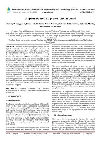
Some technologies, such as selective laser melting (SLM), selective laser sintering (SLS), and fused deposition modelling (FDM), melt or soften materials to create the layers,whilstothers,suchasStereolithography,cureliquid materials (SLA). Each approach has advantages and disadvantages, and as a result, some firms give an option between powder and polymer for the substance that the item is made of. The primary factors considered while selectinga machinearenormallyitsspeed,thecostofthe printedprototype,thecostandvarietyofmaterials,andits colour capabilities. [4] Stereolithography is a type of lithography that uses (SLA) When exposed to UV light, photosensitivemonomerresinsphotopolymerizes,whichis thebasisforStereolithography.
A low power HeCd or Nd: YVO4 laser (up to 1000 mW in contemporarymachines)isusedastheUVlightsource.[5] Curingofsolidground(SGC)SGCisaphotopolymer-based additivemanufacturingprocessinwhichthelayergeometry iscreatedusingamaskandahigh-poweredUVlamporlaser source. [6] FDM technology is highly adaptable and easily integrates with computer aided design (CAD) software programmes. FDM is the most widely used technique for creating conceptual models, prototypes, and engineering components.Thefinalproduct'squalities,likeasstrength, surfacepolish,andporosity,arehighlyreliantontheFDM processsettings.
International Research Journal of Engineering and Technology (IRJET) e-ISSN: 2395-0056
Volume: 09 Issue: 09 | Sep 2022 www.irjet.net p-ISSN: 2395-0072
As FDM is widely accepted as one of the promising technologies among industrial sectors, research is being conducted to increase the variety of materials that canbe processed using this technology in order to sustain competitionasitreducesdevelopmenttimeandcostofthe product,whichistheneedofthehour.Recently,researchers haveexaminedavarietyofmethodstoexpandtherangeof materialsaccessiblefortheFDMprocess,whichhasresulted inanexpansionofthescopeofFDMinnumerousproduction industries. The key advantages of this method are that no chemicalpost-processingisnecessary,therearenoresinsto cure,andthemachineandmaterialsarelesscostly,resulting inamorecost-efficientprocedure.
Because of its exceptional electronic characteristics, graphene has been identified as a viable material for electronicapplications.Manymethodshavebeendeveloped overthelastdecadebymaterialscientistsandengineersto prepare large scale and high-quality graphene samples, which provide the foundation for graphene device level applications, and carrier mobility is one of the most concerned figures of merits of graphene quality as they grow.
1. Amicrowaveapproachforextracting grapheneandfew graphene stacks from turbostatic carbon fibres is a prominent method. In the unzipping of tubular carbon structures, microwave radiation is employed as a supplementary energy source in combination with the hydrogenperoxide,amildoxidisingagent.Thisreduces thedifficultiesassociatedwithexerciseoxidationwhile alsosignificantlyshorteningtheoverallprocessingtime. In this investigation, a two-stage microwave treatment was performed, with the first step in the presence of hydrogen peroxide and the following dry expansion of exfoliatedCFresultinginenlargedcarbonfibres.Initially, 5 lm finely chopped carbon fibres were submerged in hydrogen peroxide and microwaved for 30 minutes, resulting in the removal of the CF’s outer sheath and partial expansion of its graphene layers. Microwave heated carbon fibres have been seen to undergo fast oxidation with increased porosity. The Xray diffractogramsoftheseextendedcarbonfibresreveal a verystrongpeakat12inadditiontothetypicalgraphitic peak at 26, suggesting significant enlargement of the graphiticlayers.Thepresenceofstackedgraphenelayers in combination with locally folded graphene stacks, as revealed by TEM micrographs, is also suggested by the sharppeaks.Thewaterwascookedoffinapproximately 20minutes,leavingbehindadrylookingsubstanceinthe flask,thisproductwasreexposedtomicrowaveradiation in order to expand further. The graphene layers of CF grew instantly, resulting in the production of weakly adheringgraphenelayers.
Althoughthebulkoftheoxidegroupswerepredictedto beremovedduringthemicrowavestage,someresiduesof theoxideswereeliminatedduringthisphase.Graphene with primarilydisc shaped platelets,as revealed by SM and TEM, indicates that the cutting process in carbon fibres is predominantly cross sectional, as opposed to longitudinal unzipping as described in other tubular carbonnanostructuressuchasMWCNTandSWCNT.
2. A quick, fast and straightforward method for obtaining fewgraphenelayersbymicrowaveinducedexfoliationof turbostaticcarbonfibreshasalsobeenstudied.Theentire procedure is straightforward, involving the use of environmentallyacceptablechemicalssuchashydrogen peroxide and a residential microwave as an external energysource.Whenthesameprocedurewasrepeated withhighlygraphitizedcarbonstructuressuchascarbon nano-fibresandgraphite,itdidn’tyieldgraphenebecause thecarbonatomsinthesestructuresarechemicallyless accessible for oxidation reactions, resulting in a significantlylowerdegreeofoxidationandmakingthese structures difficult to exfoliate. The emphasis is on the widely utilised sonication, with the most recent insight into sonication induced flaws, freshly investigated ball milling,developingfluiddynamicsinthelastthreeyears andrevolutionarysupercriticalfluid.Thediscussiontook placeonhowtoeffectivelyproducehighqualitygraphene. Differentexfoliationproceduresarethuslinkedtogether by a similar mechanism. Then we will go through mechanical exfoliation techniques in detail, such as the originalmicromechanicalcleavage,themostoftenused sonication, the newly discovered ball milling, the lately developingfluiddynamics,therevolutionarysupercritical fluidandsoon.Finally,thefindingsandperspective:the ability to produce graphene on a wide scale has been made achievable via sonication assisted liquid phase exfoliation of graphite. Coleman’s group originally reported the high yield synthesis of graphene by sonication aided liquid phase exfoliation of graphite in 2008,aftertheirexpertiseindispersingcarbonnanotubes bysonication.
Graphene based materials have extraordinary electrical, optical,andmechanicalcapabilities,whichhassparkedalot ofscientificcuriosityaswellasalotofpromiseforawide rangeofapplications.Furthermore,duetoadvancementsin preparation processes, the variety of graphene-based compoundsisexpanding.
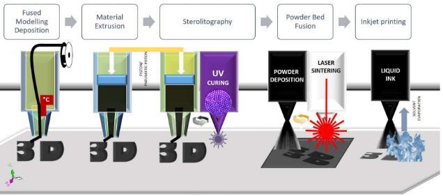
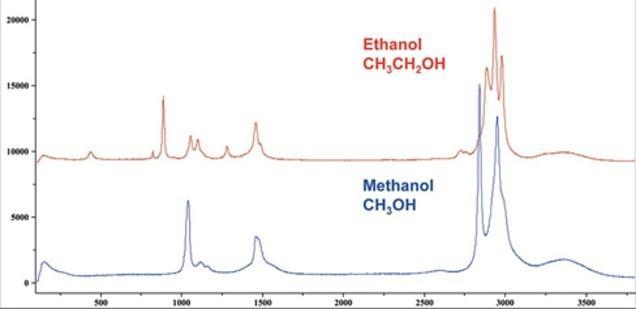
Ramanspectroscopyisaflexiblemethodforidentifyingand characterising these materials' chemical and physical characteristics,bothinthelaboratoryandonalargescale. This approach is so significant that most studies on these materialsincludeatleastoneRamanspectra.
International Research Journal of Engineering and Technology (IRJET) e-ISSN: 2395-0056
Volume: 09 Issue: 09 | Sep 2022 www.irjet.net p-ISSN: 2395-0072
Graphene possesses exceptional electrical, optoelectronic, and mechanical characteristics, as well asa wide range of deviceapplications.AllRamanmodesinintrinsicgraphene, includingthefirst-orderGmodeandDR-activatedfirst-and secondorderRamanmodes,havebeeninvestigated.TheC, LB, and 2D modes in NLGs have also been thoroughly examined, as they are highly sensitive to the number of layersNandstackingorder(AB,ABC,andtwiststacking).
NLG resonance Raman spectroscopy was also reported. Externaldisturbancestographeneflakesmayinfluencetheir latticevibrationsaswellasbandstructures,whichRaman spectroscopymayshow.
Theeffectsofpointdefects,linedefects,andedgesontheD, G,and2Dmodeshavebeenthoroughlyaddressed,andithas been convincingly established how to use Raman spectroscopytoexaminethenatureofdefectsingraphene. The Raman spectral characteristics of the C, LB, and 2D modes,aswellastheintensityoftheGmodeofNLGandthe Simodeofthesubstrate,havebeenusedtodeterminethe valueofNofgrapheneflakes.
Ramanspectroscopyhasalsobeenusedtostudygraphenebasedmaterialssuchnanographene,carbondots,graphene oxide, epitaxial graphene on SiC, CVD-grown NLG, and graphene-based van der Waals heterostructures. Raman imaginghasalsobeenproventoofferregionallydispersed information about graphene flakes' number of layers, stackingorder,edges,strain,andgrowthmethod.
Finally,Ramanspectroscopyhasbeendemonstratedtobea non-destructive, on-line characterization technique for monitoringthepropertymodificationordesignedfunction ondemandofgraphenematerialsinrelateddevicessuchas FETs,energystoragedevices,solarcells,OLEDs,NEMS,and graphene-basedvdWheterostructures.Therearenumerous well-resolved bands in the Raman spectra of single-layer graphene (SLG). [16] The E2G vibrational mode of the Brillouinzone(BZ)centrephononscorrespondtotheGband. The D band, also known as the defect-related or disorderrelated mode, is associated with the breathing mode of a carbonringandresultsfromtheresonantintervalleyprocess near the BZ edge. Because of the relaxation of the phonon momentumconservationprinciples,thisbandemergeswith defects in graphene. The intervalley resonant process is representedbytheD0band.Evenintheabsenceofdefects, the2Dband,anovertoneoftheDband,isalwayspresentin theRamanspectraofgraphene.
Duetounusualphysiochemicalfeatures,graphene,asingle atom thick layer of two- dimensional closely packed honeycomb carbon lattice, and its derivatives havegottenalotof attention in the biomedicalarea. The valuable physicochemical properties of graphene-based bioelectronicsdevices,suchashighsurfacearea,excellent electrical conductivity, remarkable biocompatibility, and easeofsurfacefunctionalization,haveshowngreatpotential in applications such as electrochemical biosensors for biomarkeranalysis.
Due to its unique physicochemical features, graphene, a single 2-dimensional(2D) layer of a hexagonal structure comprised of sp2 hybridised carbon atoms, and its derivatives have gained increased attention in biomedical domains. High surface area, great electrical conductivity, robust mechanical strength, exceptional thermal conductivity, and ease of surface functionalization are all features of this material.In particular, the rate of electron transfer is inversely related to the exponential distance between the electrode surface and the molecules electroactive redox site. Because electron transmission betweengrapheneandredoxactivemoleculesusuallyoccurs at the graphene layers edges or flaws in the basal plane, graphene’slargesurfaceareamakesitanidealconducting medium for electrical charge and heterogeneous electron transfer.
Graphene is amaterialwith alot of intriguing features.Thesecharacteristics,togetherwiththeabundance ofcarboninnature,havemadegrapheneahighlyresearched substancewithawiderangeofapplications.Thefollowings aresomeofthem:
1. Thermalandelectricalconductivityishigh.
2. Extremesupplenessandadaptability
3. Highabrasionresistance
4. Resistanceishigh.
International Research Journal of Engineering and Technology (IRJET) e-ISSN: 2395-0056
Volume: 09 Issue: 09 | Sep 2022 www.irjet.net p-ISSN: 2395-0072
5. Graphene is 200 times stronger than steel,withresistanceequivalentto diamond but much lighter.
6. Theeffectsofionisingradiationareunaffected
7. Sunlightcanbeusedtogenerateelectricity.
8. Materialthatistransparent
9. High densitypreventsHelium atomsfrom passing through,butitdoesenablewatertogetthrough,which evaporates at the samepaceas if it were in an open container.
10. Antibacterialproperties.
11. Bacteriaareunabletodevelopinthisenvironment.
12. When conducting electrons, the low Joule effectcausesheating.
Incomparisontoothercompounds,ituseslesselectricity.
Asimulationistheimitationoftheoperationofareal-world processorsystemovertime.Simulationsrequiretheuseof models; the model represents the key characteristics or behavioursoftheselectedsystemorprocess,whereasthe simulationrepresentstheevolutionofthemodelovertime. Often,computersareusedtoexecutethesimulation.
The primary goal of a thermal study of the nozzle is to determinethetemperaturedistributionoftheliquidand whether the liquid inside the nozzle is hotter than the ambienttemperature. Also,ifthetemperatureinsidethe nozzleclimbsaboveambient,wecanidentifywherethe finsshouldbeinstalledtothenozzle.
Thermal analysis of platform preheating of a 3D printer:
Theplatformmustbepreparedbeforeprintingsothatthe modelstickstotheplatformsufficientlytoallowprinting withoutthemodelshifting.Platformpreheatingisoneof thekeystosuccessfulprintingontheUP.
To determine the velocity of the liquid material flowing out of the nozzle end, a velocity study of the nozzle attachment is performed. Again, the feeder requires a particular amount of force and velocity to transfer the materialthroughthenozzleatthestartoftheattachment, so we can establish these parameters using velocity analysis.
ElectrochemicalExfoliation:
For creating graphene from graphite, Electrochemical Exfoliationisapotentialbulkapproach.Naturalgraphitein the form of foils, rods, sheets or highly oriented pyrolytic graphite, are the most commonly employed graphite electrodes in electrochemical exfoliation. To extend the interlayerspacebetweengraphenelayers,electrochemical exfoliationofgraphitereliesonefficientionintercalations amonggraphenelayers.
Since graphene in the market is much more costly so we cannoteventhinkaboutbuyingready-madeink.Sowehave togothroughnumberofstepsforpreparingtheink.Andthe sonicationprocessisalsocriticalbutitgaveaneasysolution toourproblem.
Inknumber01
ThefirstinkmadewastheGlycerolbasedink.0.3gramof extractedgraphenepowderwastaken.
Added20mlglycerolasabasesoasthepowderwillmix withitproperly.
Then took the solution and kept it in the sonicator for around30minutes+30minutesfordispersion.
But the proper expected mixture in 60 minutes wasn’t obtainedsothewholeprocedurewasrepeatedagain.
Inknumber02
Sincetheglycerolbasedidn’twork,theglycerolbasewas replacedwiththeToluenebase.
The mixture of 10 ml of toluene with 10 ml of calcium hypochloritewasmixedthe0.3gmofgraphenepowder.
Thenthesolutionwaskeptinthesonicatorforaround30 minutes+60minutesfordispersion.
Afterthesonicationprocesswesolutiongotdispersedbut it was somewhat lacking the expectation, so the whole procedurewasrepeatedagain.
Inknumber03
Thethirdandfinalinkwaswiththeuseofpuretoluene.
30mloftoluenebasewastakenandmixeditwith2.0 gmofgraphenepowder.
Thesolutionwaskeptinthesonicatoragainforaround 60minutes+60minutesfordispersion.
2022, IRJET | Impact Factor value: 7.529 | ISO 9001:2008 Certified Journal | Page25
International Research Journal of Engineering and Technology (IRJET) e-ISSN: 2395-0056
Volume: 09 Issue: 09 | Sep 2022 www.irjet.net p-ISSN: 2395-0072
After120minutesi.e.intwohoursintotal,therequired mixturewasobtainedsuccessfullywiththeexpected properties.
This required mixture was nothing but the graphene ink whichwasthenusedtodevelop3Dcircuit.Asolution-based andscalablegrapheneinkwasdevelopedandcharacterized foritsproperties.
Sonication therapy causes micro streaming, which can improvemasstransferduringcavitationalbubblecollapse. As a result, cell wall is destroyed allowing for improved contact and interactions of solvents in and out of plant component. The most critical step in the creation of nanofluids is Sonication. We followed magnetic stirring of mixtureinamagneticstirrer,sonicationisperformedinan ultrasonication part, ultrasonic vibrator and mechanical homogenizer.
Graphene ink, like other conductive inks,maybe used to print the objects that carryheat and electricity. Solvents, surfactants and graphene powder are mixed into a thick paste to make graphene conductive ink. The product'sprimaryuseisinthefieldofprintedelectronics.A C-C bond contributes to the sp2 firmly linked carbon in graphene, which has a 2-dimensional structure and honeycomblatticeshape.
Alinearactuatorisamechanicaldevicethatgeneratesforce andmotioninastraightline. Asteppingmotorisusedasthe source of rotary power in a stepper motor-based linear actuator. Instead of a shaft, the rotorcontainsa threaded precisionnut.Aleadscrewisusedtoreplacedshaft.Linear motion is provided directly through the nut and threaded screwastherotorrotates(asinatraditionalsteppermotor). The rotary to linear conversion should be done directly inside the motor, as this substantially simplifies design of rotary to linear applications. This provides excellent resolution and accuracy, making it ideal for applications requiringprecisionmovements.
In every 3d printer there is a heating coil set up near the extrudernozzle.Thisheatingcoilina3dprinterisusedto convertthesolidstringofPLAintotheviscousliquid.Since wehaveusedrawmaterialinourprojectandthismaterialis alreadyintheliquidstatesowedon’tneedtheheatingcoil in our mechanism.Hence,we have eliminated the heating coil.
Wireextrudersareemployedinthecurrentmechanismto pass ink from the printer andobtainthe product. Becausewe used a syringe system (linear actuator), our mechanism isunique. Asaresult,we had todetachthecurrentwireextrudermachineryandreplaceit withourown.
Ourgoalis tocreatean attachment that can bereadily installedona3dprinterwithoutcausinganydamagetothe existing 3d printer's parts orincreasingthe load and pressureonthe3dprinter. Asaresultofwhichweusedthe chromatographyprocessforprinting,inwhichthebase(in ourcase,toulin)separatesfromthesolidcombination.
Thepresent programmeisdesignedto move the extruder nozzleinaregularpattern,butwecreatedanewmechanism to pass our ink through. As a result, the movement of our mechanismisdistinct.So, wehadtobuildanotherG-code applicationtoobtaindesiredproduct.
We have presented Graphene and thetechniques for extractingGraphene,aslightweightmaterialshavebecomea newtrendinthematerialworld. Thehigherthegraphene concentration, the lower the apparent density of the graphene-basedstructure,andthehigherthecarbonatom saturation,thelighterthematerial. In3Dprinting,extrusion andprintingspeedsarecritical.
Togetintakeandoutletspecificationssuchasmotorpower, motortype,feederforceandvelocity,nozzleoutletdiameter, andmaterialvelocityatseveralcruciallocationsduringthe nozzleattachment,asimulationprogrammeisused.
Electrochemical exfoliation, we believe will become more important in creation of graphene materials. The ink developedissolutionbasedandscalable,anditsproperties havebeendescribed.
[1] Stoller,M.D.;Park,S.;Zhu,Y.;An,J.;Ruoff,R.S.Graphenebasedultracapacitors.NanoLett.2008,8,3498–350
[2] Weiss,NathanO.,HailongZhou,LeiLiao,YuanLiu,Shan Jiang, Yu Huang, and Xiangfeng Duan. "Graphene: an emerging electronic material." Advanced materials 24, no.43(2012):5782-5825.
International Research Journal of Engineering and Technology (IRJET) e-ISSN: 2395-0056
Volume: 09 Issue: 09 | Sep 2022 www.irjet.net p-ISSN: 2395-0072
[3] Lee,Changgu,XiaodingWei,JeffreyW.Kysar,andJames Hone. "Measurement of the elastic properties and intrinsicstrengthofmonolayergraphene." science 321, no.5887(2008):385-388.
[4] Balandin,A.A.,S.Ghosh,D.Teweldebrhan,I.Calizo,W. Bao, F. Miao, and C. N. Lau. "Extremely high thermal conductivity of graphene: prospects for thermal management applications in silicon nanoelectronics." In 2008 IEEE Silicon Nanoelectronics Workshop,pp.1-2. IEEE,2008.
[5] Georgakilas, Vasilios, MichalOtyepka, Athanasios B.Bourlinos, Vimlesh Chandra,NamdongKim, K. ChristianKemp,PavelHobza,RadekZboril,andKwang S. Kim. "Functionalization of graphene: covalent and non-covalent approaches, derivatives and applications." Chemical reviews 112, no. 11 (2012): 6156-6214.
[6] Song,Yang,YananLuo,ChengzhouZhu,HeLi,DanDu, andYueheLin. "Recent advances in electrochemical biosensors based on graphene two-dimensional nanomaterials." Biosensors and Bioelectronics 76(2016): 195-212.
2022, IRJET | Impact Factor value: 7.529 | ISO 9001:2008 Certified Journal