International Research Journal of Engineering and Technology (IRJET) Volume: 09 Issue: 08 | Aug 2022
www.irjet.net
e-ISSN: 2395-0056 p-ISSN: 2395-0072
Design of Symmetrical Seven Level Multi Level Inverter Mr. Mohith R1, Mr. Dayananda T B 2 1Associate
Professor in Electrical and Engineering, Dr. Ambedkar institute of technology, Bengaluru , India of Electrical and Electronics Engineering, Dr. Ambedkar institute of technology, Bengaluru, India -------------------------------------------------------------------------***--------------------------------------------------------------------------is made of three capacitor connected in series. After ABSTRACT 2Department
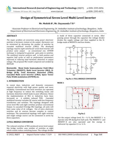
passing power through the capacitor the voltage divider divides the supply voltage and then supplied to the Hbridge made of MOSFETs and four diodes.
The major problem of conversion using power electronic switches is harmonic content at the output. Harmonics can be minimized by decreasing the number of switches by cascaded multilevel inverter (CMLI). The developed topology requires eight switches for seven level inverter will produce same output as conventional one. SVPWM technique is instigated to generate gate pulse to switches. The multilevel inverter perform well in both positive and negative half cycles as well as performance parameters improved in reducing total harmonic distortion in output voltage. The proposed MLI model compared and verified by MATLAB.
Keywords: Metal Oxide Semiconductor Field Effect Transistor (MOSFET), Multi Level Inverter (MLI), HBridge (H-B), Total Harmonic Distortion (THD), Cascaded Multi Level Inverter (CMLI), Space Vector Pulse Width modulation (SVPWM) etc.
Fig No.1: FULL BRIDGE CONVERTER
1. INTRODUCTION
MODE 1
In recent days, industries and domestic consumers required electricity with high power quality and more reliability. Conventional two level inverters are operated at high frequency to reduce the switching losses and harmonic distortion which leads to poor efficiency. Hence the implementation of MLI in industries have been increased, as it exhibits reduced THD. Cascaded multilevel inverter includes DC source with low frequency transformer and switches. The topology designed with seven level MLI and eight switches produce conventional Output. In cascaded H-bridge MLI topology, all units will have same value of dc voltages. Use of extra electronic switches and dc sources become complex in control technique. The symmetrical topology with eight switches and single voltage source can be connected in series by three capacitors.
Fig No.2 For the output voltage level, V0 = ⅓ Vi, the MOSFET 1 is operate only ON during first half cycle. The MOSFET 5 and MOSFET 8 are also operated and the energy is delivered by capacitor C1 i.e. ⅓ Vi.
2.FULL BRIDGE CONVERTER The reduced switches of MLI produced seven level output like bridge rectifier uses number of switches as eight which results reduce switching losses. The voltage divider
© 2022, IRJET
|
Impact Factor value: 7.529
|
ISO 9001:2008 Certified Journal
|
Page 368