International Research Journal of Engineering and Technology (IRJET) e-ISSN: 2395-0056

Volume: 09 Issue: 08 | August 2022 www.irjet.net p-ISSN: 2395-0072
International Research Journal of Engineering and Technology (IRJET) e-ISSN: 2395-0056
Volume: 09 Issue: 08 | August 2022 www.irjet.net p-ISSN: 2395-0072
1
, Kanchan B. Kanagali2
1PG Student, Dept of civil engineering, K.L.S Gogte Institute Of Technology, Belagavi, Karnataka, India.
2Assistant Professor, Dept of civil engineering, K.L.S Gogte Institute Of Technology, Belagavi, Karnataka, India. ***
Abstract - Progressivecollapsecanbedefinedasthe failure of a structure due to the spread of a local failure of the structure. Progressive collapse is because of manmade, natural, which can be because of fires, explosions, earthquakes etc. causing failure of support elements which tendstocauseprogressivecollapsefailure.Thepurposeofthis study is to understand the nature and process of progressive collapse. This project involves the use of ETABS to perform analysis of a reinforced concrete structure. ETABS is used to observe local failure and its effect on the overall structure. Several column failure conditions are studied and as per General Service Administration (GSA) guidelines.
Key Words: Progressive Collapse, General Service Administration Guidelines, ETABS 2013
Whenapartofastructurethatisassumedtohavecollapsed, orbeenseverelydamaged,byanyaccidentaleventtheterm is called localized failure. Localized failure leads to progressivecollapse. Progressivecollapseisainitiallocal failureofaverticalstructuralcomponentwhichfurtherleads to the collapse of adjoining members, which causes additionalcollapseofthestructure.Whenacolumnfails,it resultsinthefailureofadjoiningbeamandcolumns,which eventuallyleadstotheentirecollapseofthestructure.The failureofcolumnmightoccurbecauseofbombexplosion,a car colliding with column in a parking, fire explosion, earthquake. A shear wallis a vertical element that is designedtoresistlateralforces,likewindandseismicloads
The General Services Administration (GSA) (2003) is an independentagencyoftheU.S.government.TheGSAlimits weresettodecreasethepossibilityforprogressivecollapse of a buildings and, assess the potential for progressive collapse of buildings, and develop potential upgrades to facilitiesifrequired.Theloadingcombinationaccordingto theGSAcodedependsontheanalysistype
Thefollowingstaticlinearelasticanalysisapproachmaybe used to assess the potential for progressive collapse. The
followinganalysisprocedureshallbeperformedusingwellestablished linear elastic, static analysis techniques. It is recommendedthat3-dimensionalanalyticmodelsbeusedto accountforpotential3-dimensionaleffectsandavoidoverly conservativesolutions.Nevertheless,2-dimensionalmodels may be used provided that the general response and 3dimensionaleffectscanbeadequatelyaccountedfor.
a. Analyse for the sudden loss of a column for one floor above grade (1 story) located at or near the middleoftheshortsideofthestructure.
b. Analyse for the sudden loss of a column for one floor above grade (1 story) located at or near the middleofthelongsideofthestructure.
c. Analyse for the sudden loss of a column for one floorabovegrade(1story)locatedatthecornerof thestructure
a. Analyse for the sudden loss of 1 column that extendsfromtheflooroftheundergroundparking areaoruncontrolledpublicgroundfloorareatothe nextfloor(1story).Thecolumnconsideredshould beinteriortotheperimetercolumnlines.
Analyzefortheinstantaneouslossoftheentirebearingwall alongtheperimeteratthecornerstructuralbayortheloss of 30 linear feet of the wall (15ft in each major direction)(whicheverisless)foronefloorabovegrade.
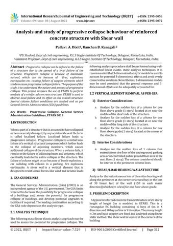
Atypicalreinforcedconcreteframedstructureof20storey height of height 3m is modeled in ETABS. This is a rectangular RC building containing :6 bays of 6m in X directionand10baysof6minYdirection.Thestoreyheight is3mandbasesupportarefixedandanalyzedusinglinear staticmethod.Theshearwallislocatedatthecornersofthe building
International Research Journal of Engineering and Technology (IRJET) e-ISSN: 2395-0056
Volume: 09 Issue: 08 | August 2022 www.irjet.net p-ISSN: 2395-0072
Theanalysisisdoneusinglinearstaticanalysismethod.The designofstructuralmembersisdoneasperIS456:2000.
Liveload:2kN/m2
Floorfinish:1.5kN/m2
Wallload:Exteriorwall=13.8kN/m Interiorwall=9kN/m
Thecombinationofloadtakenintoaccountis Load=2(DL+0.25LL)
Where, DLisDeadLoadandLLisLiveLoad
2isdynamicfactor
3.2
Fig-1 planview(Shearwallsatthecorner)
GIVEN BELOW:
Characteristiccompressivestrengthofconcrete(fck):30 N/mm2
YieldStrengthofreinforcingsteel(fy):500N/mm2
Beamsize:300x550mm
Slabthickness:150mm
Shearwallthickness:250mm Wallthickness:Exteriorwalls230mm Interiorwalls150mm
InteriorColumnssizes:
850x850mm(Baseto5th floor)
800x800mm(6th to10th floor)
650x650mm(11th to15th floor)
450x450mm(16th to20th floor)
ExteriorColumnsizes
800x800mm(Baseto5th floor)
600x650mm(6th to10th floor)
500x500mm(11th to15th floor)
450x450mm(16th to20th floor)
Deadload:Selfweightofthestructure
Demand Capacity Ratio is the ratio between structural member force after removal of column to the member's ultimatestrengthorcapacityofthemember.
DCR=Qud/Que
Qud=demandingoractingforceinmemberorconnection orjoint.
Que = Un factored capacity of the member or expected ultimatestrengthofmember.
DCRacceptancecriteriaareasfollows,
DemandCapacityRatio<2.0forregularstructures.
DemandCapacityRatio<1.5forirregularstructures.
DemandCapacityRatio<3.0forsteelstructures.
Calculation of Mulimit to determine DCR for the structural members are given below.
DCR=Mu/Mulimit
Structurewithshearwall
Beam: Breadth,b=300mm Depth,D=550mm
Cover,d’=30mm
Effectivedepth,=D-d'=550-30=420mm fck=30N/mm2 fy=500N/mm2
Calculationofultimatemoment:
2022, IRJET | Impact Factor value: 7.529 | ISO 9001:2008 Certified Journal | Page313
International Research Journal of Engineering and Technology (IRJET) e-ISSN: 2395-0056
Mulimit=0.133*fck*b*d*d =0.133*30*300*520*520 =323.66kN-m
Structurewithoutshearwall: Beam: Breadth,b=300mm Depth,D=500mm Cover,d’=30mm
Effectivedepth,=D-d'=500-30=470mm fck=30N/mm2 fy=500N/mm2
Calculationofultimatemoment: Mulimit=0.133*fck*b*d*d =0.133*30*300*470*470 =264.42kN-m
Reinforced concrete building is modelled in ETABS and is analyzed using linear static analysis method. Progressive collapsepotentialofabuildingisanalyzedfortwodifferent casesofcolumnremoval.
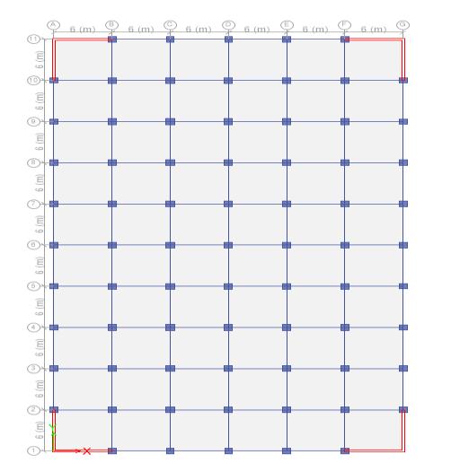
Case1:Exteriorcolumnremovalatgroundfloor
WhenColumnC66isremovedatBasefloor,mostcritically affectedcolumnsandbeamsare:
Columns:C65,67andC44andBeams:B74,B32,B75
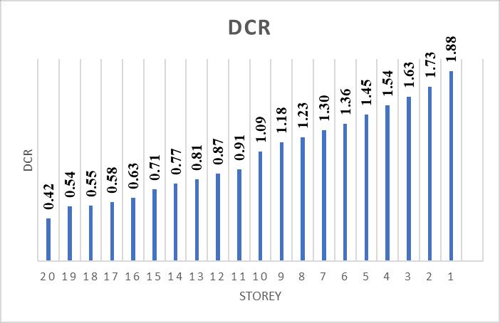
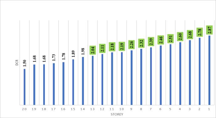
Variations of Demand Capacity Ratios for above beams is given: BeamB74,75
Fig 4.1 PlanviewExteriorcolumnremovalatgroundfloor
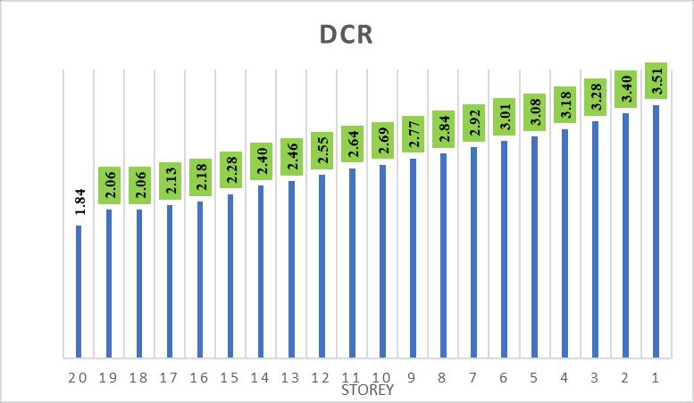
Chart -1:DemandCapacityRatioV/Sstoreyofbeam BeamB32
Chart -2:DemandCapacityRatioV/Sstoreyofbeam
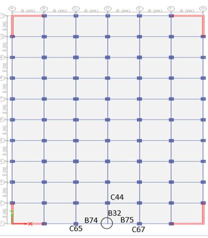
Case2:Interior(Central)columnremovalatgroundfloor.
Fig4.2 Planview(Interiorcolumnremovalatground floor.)
Volume: 09 Issue: 08 | August 2022 www.irjet.net p-ISSN: 2395-0072 © 2022, IRJET | Impact Factor value: 7.529 | ISO 9001:2008 Certified Journal | Page314
International Research Journal of Engineering and Technology (IRJET) e-ISSN: 2395-0056
Volume: 09 Issue: 08 | August 2022 www.irjet.net p-ISSN: 2395-0072
WhenColumnC18isremovedatBasefloor,mostcritically affectedcolumnsandbeamsare:
Columns:C11,C17,C25,C19andBeams:B104,B105,B37, B36.
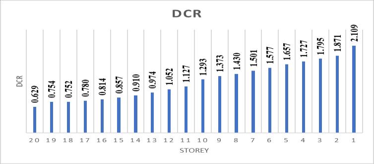
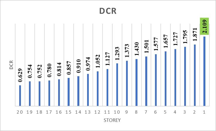
VariationsDCRvaluesfortheabovebeamsrespectivelyis givenasfollows
Beam36
Chart -6: DemandCapacityRatioV/Sstoreyofbeam
4.1 Comparison of DCR between structures with and without Shear wall Case 1: Exterior column removal at ground floor.
DCR value are compared for structures with and without Shearwall for
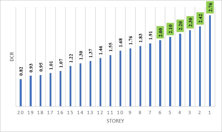
Beam74,75:
Structurewithshearwall
Chart -3: DemandCapacityRatioV/Sstoreyofbeam
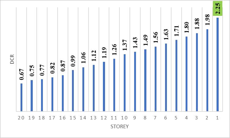
Beam37
Chart -4: DemandCapacityRatioV/Sstoreyofbeam
Beam104
Chart-7:DemandCapacityRatioV/Sstoreyofbeam Structurewithoutshearwall
Chart-8:DemandCapacityRatioV/Sstoreyofbeam B74,75
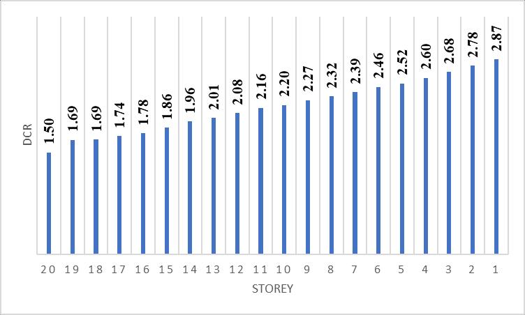
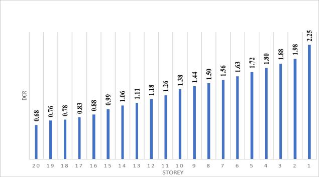
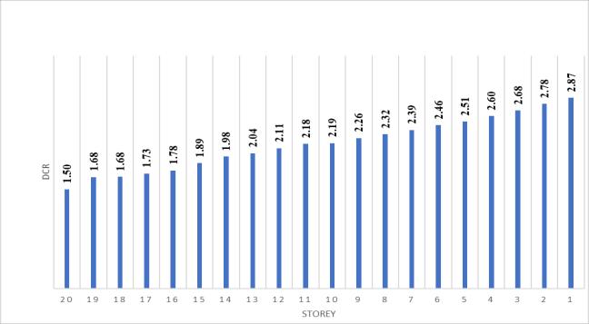
Chart -5: DemandCapacityRatioV/Sstoreyofbeam
Beam105
© 2022, IRJET | Impact Factor value: 7.529 | ISO 9001:2008 Certified Journal | Page315
International Research Journal of Engineering and Technology (IRJET) e-ISSN: 2395-0056
Volume: 09 Issue: 08 | August 2022 www.irjet.net p-ISSN: 2395-0072
Beam32: Structurewithshearwall
Chart-12:DemandCapacityRatioV/SstoreyofbeamB36
Beam37: Structurewithshearwall
Chart-9:DemandCapacityRatioV/SstoreyofbeamB32

Structurewithoutshearwall
Chart-13:DemandCapacityRatioV/SstoreyofbeamB37
Structurewithoutshearwall
Chart-10:DemandCapacityRatioV/SstoreyofbeamB32
Case 2: Interior (central) column removal at ground floor.
DCRvaluearecomparedforstructureswithandwithout Shearwall for
Beam36: Structurewithshearwall
Chart-14:DemandCapacityRatioV/SstoreyofbeamB37
Beam104: Structurewithshearwall
Chart-11:DemandCapacityRatioV/SstoreyofbeamB36
Structurewithoutshearwall
Chart-15:DemandCapacityRatioV/Sstoreyofbeam B104
© 2022, IRJET | Impact Factor value: 7.529 | ISO 9001:2008 Certified Journal | Page316
International Research Journal of Engineering and Technology (IRJET) e-ISSN: 2395-0056
Structurewithoutshearwall
Chart-16:DemandCapacityRatioV/Sstoreyofbeam B104
Beam105:
Structurewithshearwall
Chart-17:DemandCapacityRatioV/Sstoreyofbeam B105
Structurewithoutshearwall
Chart-18:DemandCapacityRatioV/Sstoreyofbeam B105
Based on the analytical results, the following conclusions wereobtained:
1) Case1:Exteriorcolumnremovalatgroundfloor
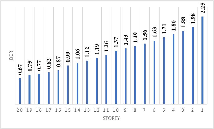
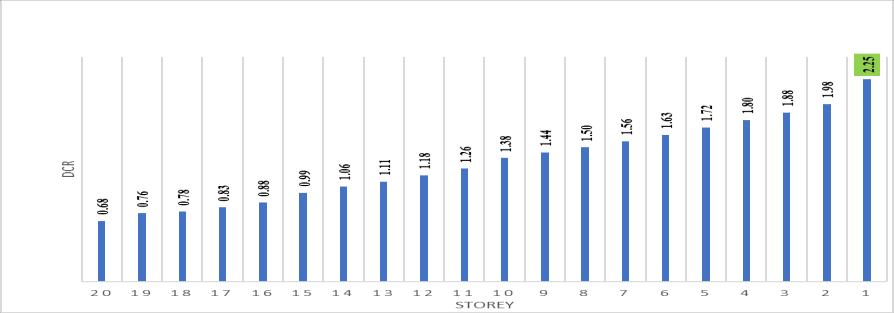
i. Beams (B74,75) tends to fail from 1st to 5th storeyandbeam(B32)tendstofailfrom1stto 3rd storey, when a column is removed at 1st floor without shear wall, whereas in case of columnremovalwithshearwall(B74,75)fails at 1st storey and (B32) there was no failure observed.
ii. Axial force before and after column removal arecomparedfortheadjoiningcolumnsC65& C67,thepercentageincreaseisobservedtobe 30.9%atstorey1and18.57%atthestorey20 aftercolumnremoval.
iii. Axial force before and after column removal are compared for the columns C44 and percentageincreaseisobservedtobe19.4% at storey 1and 9.22% at the storey 20 after columnremoval
iv. ItwasobservedthattheDCRvaluesatbottom storeysexceedthelimit(2.0)comparedtotop storeys.
v. Itwasobservedthatstructurewithshearwall have higher progressive collapse resisting capacitythenstructurewithoutshearwall.
vi. Toresiststheprogressivecollapse,additional shearwallsandbracingscanbeprovided.
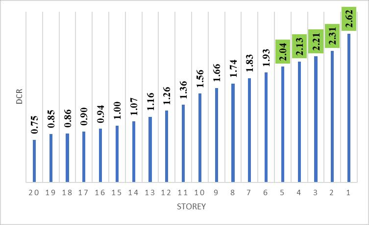
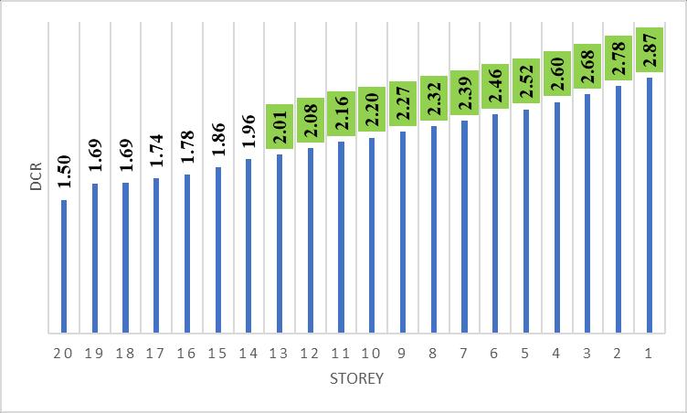
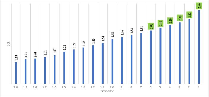
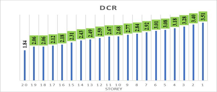
i. Beam (B36) tends to fail from 1st to 19th storey,beam(B37)tendstofailfrom1st to5th storey, beam (B104) tends to fail from 1st to 19th storey,andbeam(B105)tendstofailfrom 1st to5th storey,whenacolumnisremovedat 1st floorwithoutshearwall,whereasincaseof columnremovalwithshearwallBeams(B36) tendsto failureisarrestedupto 13thstoreyfor beam(B37)failureisarrestedat1ststorey,for beam (B104)failureisupto12th storey,and beam(B105)tendstofailat1ststorey.
ii. Axialforcebeforeandaftercolumnremovalare comparedfortheadjoiningcolumnsC11&C25 andthepercentageincreaseisobservedtobe 21.93% & 21.95% at storey 1 and 12.23% & 12.25% at the 20th storey after column removal.
iii. Axialforcebeforeandaftercolumnremovalare compared for the adjoining columns C17,C19 and percentage increase is observed to be 21.96% and 21.94% at storey 1 and 12.26% &12.21% at the 20th storey after column removal
Volume: 09 Issue: 08 | August 2022 www.irjet.net p-ISSN: 2395-0072 © 2022, IRJET | Impact Factor value: 7.529 | ISO 9001:2008 Certified Journal | Page317
International Research Journal of Engineering and Technology (IRJET) e-ISSN: 2395-0056
Volume: 09 Issue: 08 | August 2022 www.irjet.net p-ISSN: 2395-0072
iv. ItwasobservedthattheDCRvaluesatbottom storeysexceedthelimit(2.0)comparedtotop storeys.
v. Itwasobservedthatstructurewithshearwall have higher progressive collapse resisting capacitythenstructurewithoutshearwall.
vi. Toresiststheprogressivecollapse,additional shearwallsandbracingscanbeprovided.
IwouldliketothankKLSGogteInstituteofTechnology, Belagavi,Karnatakaforprovidingalltherequiredfacilities andspecialthankstofacultyforguidance.Iwouldalsoliketo thankalltherefereescitedinthispaper.

[1] Hamed Salem, Sherif Mourad “Computer-Aided AssessmentofProgressive CollapseofReinforced ConcreteStructuresaccordingtoGSACode” Journal ofPerformanceofConstructedFacilities,ASCE,Vol. 27,No.5,October1.pp529-539.
[2] F. K. Wittel; E. Masoero; H. J. Herrmann; “Progressive Collapse Mechanisms of Brittle and DuctileFramedStructures”JournalofEngineering Mechanics,ASCEVol.136,No.8,August1,2010,pp 987-995.
[3] ChristopherD.Eamon;JoshuaGriffin;M.ASCE;Alaa I. Chehab; “Collapse Resistance of RC MomentResistingFrameandShearWallStructuralSystems Exposed to Blast” Journal of Performance of Constructed Facilities,ASCE August 26 2016, pp112.
[4] MohsenAliShayanfar;MohammadMahdiJavidan “Progressive Collapse-Resisting Mechanisms and Robustness of RC Frame–Shear Wall Structures” Journal of Performance of Constructed Facilities, ASCE.March272017,pp1-12.
[5] Bing Li, Jianxiang Yang, Xin Ou “Progressive Collapse Resistance of Posttensioned Concrete Beam-Column Subassemblages with Unbonded Posttensioning Strands” Journal of Structural Engineering,ASCE2017,pp1-14.
[6] YiLi,HongGuan“Progressivecollapseresistanceof two typical high-rise RC frame shear wall structures.”JournalofPerformanceofConstructed Facilities, ASCE,2017,vol27,
Factor value:
[7] HusseinSultan, Sherif Mourad “Performance evaluation oneffects ofall types ofinfill againsttheprogressive collapse ofreinforced concreteframes”AsianJournalofCivilEngineering, Springer,vol20,2020pp-1-10.
[8] Hanlin Qiang, Jia-Xing Ma “Progressive Collapse Resistance of GFRP-Strengthened RC Beam–Slab Sub assemblages in a Corner Column–Removal Scenario”JournalofCompositesforConstruction, ASCE,2018 pp1090-0268.
[9] VinayAgarwal,SuyashGarg,Ravindranagar“Case study on strengthening methods for progressive collapse resistance of RC flat slab buildings” Institution of Structural Engineers, Elsevier, 2021pp-235-241.