International Research Journal of Engineering and Technology (IRJET) e-ISSN: 2395-0056

Volume: 09 Issue: 08 | August 2022 www.irjet.net p-ISSN: 2395-0072
International Research Journal of Engineering and Technology (IRJET) e-ISSN: 2395-0056
Volume: 09 Issue: 08 | August 2022 www.irjet.net p-ISSN: 2395-0072
1P.G. Student, Dept. of Civil Engineering, K.L.S. Gogte Institute of Technology, Belagavi, Karnataka, India 2Assistant Professor, Dept. of Civil Engineering, K.L.S. Gogte Institute of Technology, Belagavi, Karnataka, India *** -
Abstract - Progressive collapse of a building or structure can be defined as the spread of a primary local structural element failure that ultimately causes the collapse of the whole structure or a significant component of it. In order to reduce the potential for collapse associated with the loss of primary structural member such as perimeter column, outrigger systems can be used. Outriggers are horizontal structural systems inserted into the building to connect the core structure to the exterior structural elements. In this paper, A typical reinforced concrete framed building of 20 storey is modelled in ETABS. This is a rectangular RC building containing6 bays in X-directionand8 baysinY-directioneach of6minboth directions. Inaddition, the structureconsistsofa core and outrigger beams. The analysis is done using linear static analysis method.Thisstudyconsiderstwodifferentcases of column removal as specified by GSA guidelines. The percentage variations of axial force in critically affected columns and demand capacity ratios of critically affected beams are calculated. The results of the structure with outrigger beams are comparedtostructurewithoutoutrigger beams.
Key Words: Progressive collapse, Outrigger beams, General Services Administration (GSA), Linear static analysis, Alternate load path, Axial force variations, Demand Capacity Ratio (DCR).
Progressive collapse of a structure takes place when a particularstructuralmemberfailsleadingtothefailureof neighboring structural members in a progressive way. Initially,theprimarystructuralmemberfails,whichcauses thefailureofadjacentstructuralmembers,resultinginthe structuralcollapse.Progressivecollapsemaybecauseddue tomishapssuchasgasexplosions,bombattacks,fire;actions of overload, material failure, or natural phenomena. The ability to transfer loads from the collapsed columns to columnsthatareproperlydesignedandproperlyattachedto the foundation can be achieved to mitigate this failure by meansofoutriggers.Outriggersareinteriorlateralstructural members equipped to increase strength and enhance the overturning stiffness of high-rise buildings. The entire systemincludesacentralcorestructurelinkedtotheouter columns of the structure with the help of structural members termed as outriggers. The outriggers may be equipped as walls, trusses, or horizontal beams. The core
systemandperimetercolumnstogetherwiththeoutriggers regulatetheperformanceoftheentirebuilding.Reference [3]usesDCRvaluestoinvestigatetheprogressivecollapse resistingabilityofthestructure.Reference[2]discusseshow outrigger systems may mitigate toppling and disproportionate collapse of building structures and concludes that redistribution of gravity forces results in reducing the axial compressive stress, compared to the systemwithoutoutriggers.Reference[4]showsthattheuse ofoutriggerandbuiltsystemaddstodifferentloadpathsto thebuildingthatcontributestoitsresistancetoprogressive collapse.
TheU.S.GeneralServicesAdministration(GSA)established the“ProgressiveCollapseAnalysisandDesignGuidelinesfor New Federal Office Buildings and Major Modernization Projects” to make sure that the possibility of progressive collapse is addressed in the design, planning and constructionofnewbuildingsandmajorrenovationprojects.
Themethodsforprogressivecollapseanalysisincludelinear static analysis, nonlinear static analysis, linear dynamic analysisandnonlineardynamicanalysis.ALinearProcedure isasimplisticanalysisapproach,andsuggeststheusageof either a static or dynamic linear elastic finite element analysis. A Nonlinear Procedure is a more sophisticated analysis approach, and implies the use of either static or dynamicelasto-plasticfiniteelementanalysismethodsthat capturebothmaterialandgeometricnonlinearity.
LinearStaticAnalysismethodisthemostbasicandeasiest methodforprogressivecollapseanalysisinwhichoneofthe most important structural components are detached statically.
Stepstoperformtheanalysis:
1. Builda3DmodelinETABS.
2. Assign the necessary material properties, section properties, loads, load combinations as per GSA guidelines.
International Research Journal of Engineering and Technology (IRJET) e-ISSN: 2395-0056
Volume: 09 Issue: 08 | August 2022 www.irjet.net p-ISSN: 2395-0072
3. RemovethecolumnatthelocationspecifiedinGSA guidelinesseparatelyforeachconsideredcase.
4. Performthelinearstaticanalysisforthespecified staticloadcombination.
5. CalculatetheDemandCapacityRatio(DCR)forthe criticallyaffectedadjoiningstructuralmembers.
Nonlinearstaticanalysisalsoknownaspushoveranalysisis usedtoevaluatethedeflectioncapabilityandultimateload of a structure. Until higher load or higher displacement is attained,nonlinearstaticanalysisincreasespracticalloads step by step while allowing structural components to undergononlinearperformance.
It is recommended that the following downward loads be applied when assessing the possibility for progressive collapseaspresentedintheGSAGuideline.
Forstaticanalysispurposesthefollowingverticalloadshall beapplieddownwardtothestructureunderconsideration:
Load=2(DL+0.25L) (1)
Where, DLisDeadLoad,LLisLiveLoad,2isdynamicfactor
Linear dynamic analysis is also known as time history analysis.Thismethodinvolvesreal-timeeliminationofone ofthemostimportantbearingstructuralmembersresulting inreal-timelinearelasticmotions.
Stepwise collapse analysis using the nonlinear dynamic analysis approach is particularly precise and effective. It involves removal of the vertical bearing structure which affectsthematerialbynonlinearbehavior.
It is recommended that the following downward loads be applied when assessing the possibility for progressive collapseaspresentedintheGSAGuideline.
For dynamic analysis purposes the following vertical load shall be applied downward to the structure under consideration:
Load=DL+0.25L (2)
Where, DLisDeadLoad,LLisLiveLoad
value:
a. Analyse for the sudden loss of a column for one floor above grade (1 story) located at or near the middleoftheshortsideofthestructure.
b. Analyse for the sudden loss of a column for one floor above grade (1 story) located at or near the middleofthelongsideofthestructure.
c. Analyse for the sudden loss of a column for one floorabovegrade(1story)locatedatthecornerof thestructure.
a. Analyse for the sudden loss of 1 column that extendsfromtheflooroftheundergroundparking areaoruncontrolledpublicgroundfloorareatothe nextfloor(1story).Thecolumnconsideredshould beinteriortotheperimetercolumnlines.
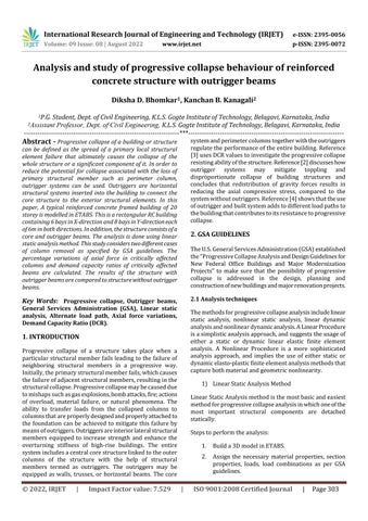
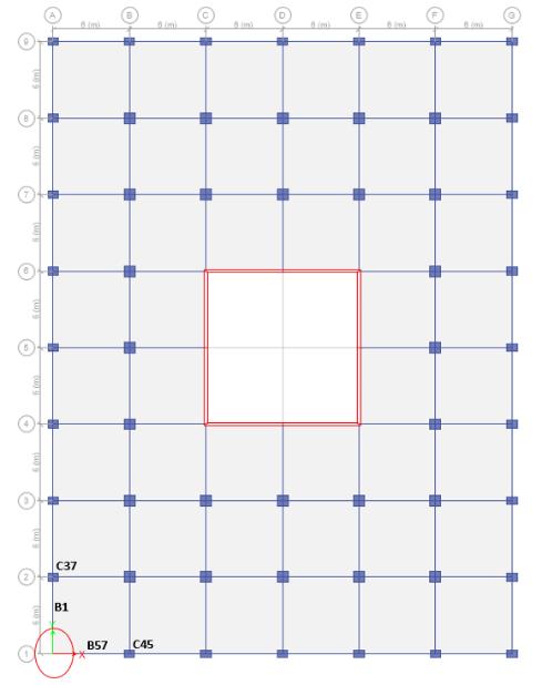
Atypicalreinforcedconcreteframedbuildingof20storeyis modelled in ETABS. This is a rectangular RC building containing6bays,eachof6minX-directionand8bays,each of6minY-direction.Thetypicalstoreyheightis3mandthe basesupportsarefixed.Inaddition,thestructureconsistsof a core and outrigger beams. The outrigger beams extend fromthecoretoperimetercolumnsinhorizontalgrids4&6 andverticalgridsC&Easshowninthefigure.Connectionis formedbetweenperimetercolumnsbymeansofoutrigger perimeterbeams.
C E 6 4
Fig -1:Planview(outriggerbeamshighlighted)
International Research Journal of Engineering and Technology (IRJET) e-ISSN: 2395-0056
Volume: 09 Issue: 08 | August 2022 www.irjet.net p-ISSN: 2395-0072
Deadload:Selfweightofthestructure Liveload:2kN/m2 Floorfinish:1.5kN/m2 Wallload:Exteriorwall=13.8kN/m Interiorwall=9kN/m
Thecombinationofloadtakenintoaccountis Load=2(DL+0.25LL)
Where,DLisDeadLoad,LLisLiveLoad,2isdynamicfactor
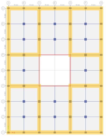
Fig -2:3Dview
Theanalysisisdoneusinglinearstaticanalysismethod.The designofstructuralmembersisdoneasperIS456:2000.
Detailsofthebuildingstructurearegivenbelow:
Characteristiccompressivestrengthofconcrete(fck):30 N/mm2
YieldStrengthofreinforcingsteel(fy):500N/mm2
Beamsize:300x500mm
Outriggerbeamsize:300x750mm Slabthickness:150mm Shearwallthickness:250mm Wallthickness:Exteriorwalls230mm Interiorwalls150mm InteriorColumnssizes:
850x850(Basefloor)
800x800(2nd to4th floor)
600x800(5th to9th floor)
600x600(10th to14th floor)
450x600(15th to20th floor)
ExteriorColumnsizes
600x800(Baseto4th floor)
600x600(5th to9th floor)
450x600(10th to14th floor)
450x450(15th to20th floor)
Demand Capacity Ratio is the ratio between structural member force after removal of column to the member's ultimatestrengthorcapacityofthemember.
DCR=Mu/Mulimit
Mu=demandingoractingforceinmemberorconnection. Mulimit=Unfactoredcapacityofthememberorexpected ultimatestrengthofmember.
DCRacceptancecriteriaareasfollows,
DemandCapacityRatio<2.0forregularstructures. DemandCapacityRatio<1.5forirregularstructures. DemandCapacityRatio<3.0forsteelstructures.
CalculationofMulimittodetermineDCRforthestructural membersaregivenbelow.
DCR=Mu/Mulimit
Outriggerbeam: Breadth,b=300mm,Depth,D=750mm Cover,d’=60mm
Effectivedepth,=D-d'=750-60=690mm fck=30N/mm2,fy=500N/mm2
Calculationofultimatemoment: Mulimit=0.133*fck*b*d*d =0.133*30*300*690*690 =569.81kN-m
Beam:
2022, IRJET | Impact Factor value: 7.529 | ISO 9001:2008 Certified
International Research Journal of Engineering and Technology (IRJET) e-ISSN: 2395-0056
Breadth,b=300mm,Depth,D=500mm Cover,d’=30mm
Effectivedepth,=D-d'=500-30=470mm fck=30N/mm2,fy=500N/mm2
Calculationofultimatemoment: Mulimit=0.133*fck*b*d*d =0.133*30*300*470*470 =264.42kN-m
Reinforced concrete building is modelled in ETABS and is analyzed using linear static analysis method. Progressive collapsepotentialofabuildingisanalyzedfortwodifferent casesofcolumnremoval.
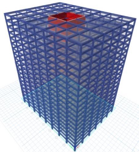
Case1:Exteriorcolumn(C18)situatedatthemiddleofthe shortsideofthestructureatstorey1
WhenColumnC18isremovedatstorey1,mostcritically affectedcolumnsare:Columns:C46,C48,C15
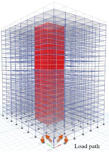
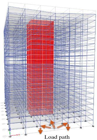
Fig -4:Loadpathdistributionwhenexteriorcolumn situatedatcornerofthestructureisremoved.
Case1:Exteriorcolumn(C18)situatedatthemiddleofthe shortsideofthestructure.
Fig -5:Case1:Exteriorcolumn(C18)situatedatthe middleoftheshortsideofthestructure
When Column C18 is removed at story 1, most critically affectedbeamsare:Beams:B59,B60,B25
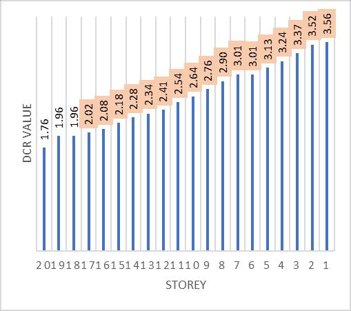
VariationsinDCRvaluesforthebeamsB59andB60
Fig -3:Loadpathdistributionwhenexteriorcolumn situatedatmiddleofshortsideofthestructureis removed.
Case2:Exteriorcolumn(C36)situatedatthecornerofthe structureatstorey1
WhenColumnC36isremovedatstorey1,mostcritically affectedcolumnsare:Columns:C37,C45
Volume: 09 Issue: 08 | August 2022 www.irjet.net p-ISSN: 2395-0072 © 2022, IRJET | Impact Factor value: 7.529 | ISO 9001:2008 Certified Journal | Page306
Chart -1:DemandCapacityRatioV/Sstoreyofbeam B59&B60
International Research Journal of Engineering and Technology (IRJET) e-ISSN: 2395-0056
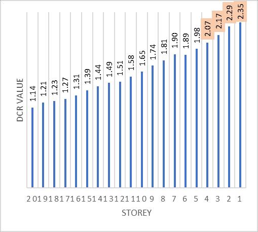
VariationsinDCRvaluesforthebeamB25
1.14 1.21 1.23 1.27 1.31 1.39 1.44 1.49 1.51 1.58 1.65 1.74 1.81 1.90 1.89 1.98 2.07 2.17 2.29 2.35 2019181716151413121110 9 8 7 6 5 4 3 2 1
DCR Value Storey
Chart -2:DemandCapacityRatioV/SstoreyofbeamB25
Case2:Exteriorcolumn(C36)situatedatthecornerofthe structure.
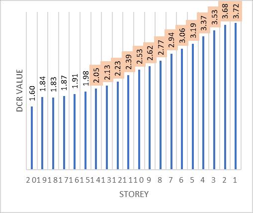
VariationsinDCRvaluesforthebeamB57
Fig -6:Case2:Exteriorcolumn(C36)situatedatthe cornerofthestructure
WhenColumnC36isremovedatstory1,mostcritically affectedbeamsare:Beams:B1,B57
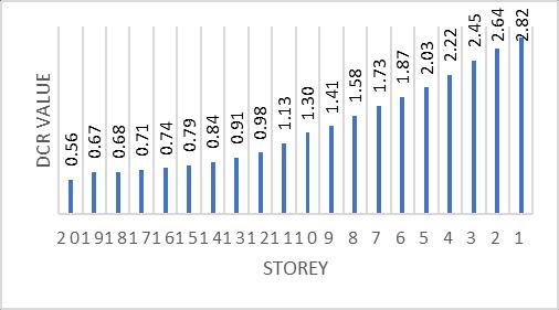
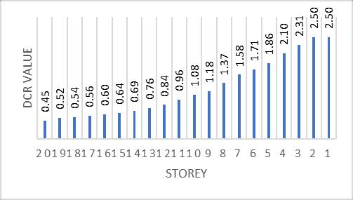
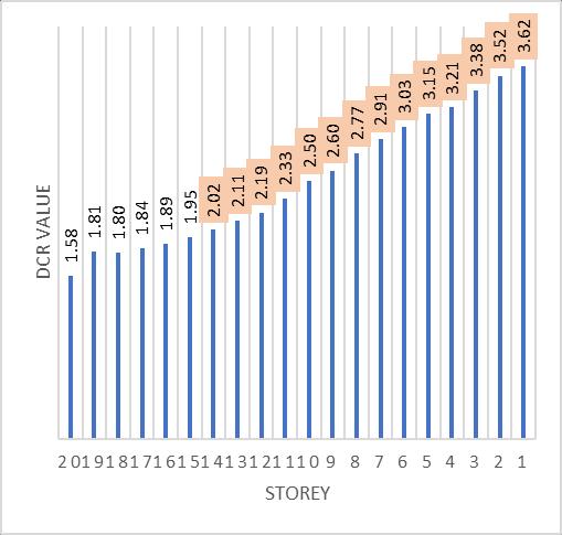
VariationsinDCRvaluesforthebeamB1
Chart -3:DemandCapacityRatioV/SstoreyofbeamB1
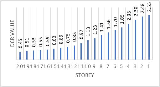
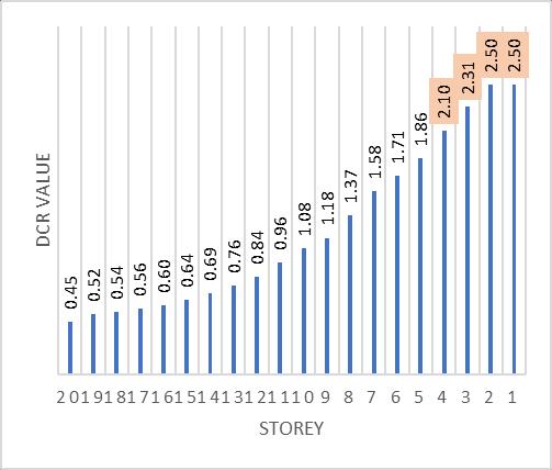
Chart -4:DemandCapacityRatioV/SstoreyofbeamB57
4.3 Comparison of DCR between structures with and without outrigger beams.
Case1:Exteriorcolumn locatedatthemiddleoftheshort sideofthebuilding: VariationsinDCRvaluesforthebeamsB59andB60 Structurewithoutriggerbeams
Chart -5:DemandCapacityRatioV/SstoreyofbeamB59 &B60
VariationsinDCRvaluesforthebeamsB25 Structurewithoutoutriggerbeams
Volume: 09 Issue: 08 | August 2022 www.irjet.net p-ISSN: 2395-0072 © 2022, IRJET | Impact Factor value: 7.529 | ISO 9001:2008 Certified Journal
International Research Journal of Engineering and Technology (IRJET) e-ISSN: 2395-0056
Volume: 09 Issue: 08 | August 2022 www.irjet.net p-ISSN: 2395-0072
Chart -7:DemandCapacityRatioV/SstoreyofbeamB25
VariationsinDCRvaluesforthebeamsB59andB60 Structurewithoutoutriggerbeams 1.65 1.86 1.85 1.89 1.93 1.99 2.06 2.14 2.22 2.34 2.50 2.59 2.75 2.87 2.99 3.12 3.16 3.31 3.44 3.57 2019181716151413121110 9 8 7 6 5 4 3 2 1
DCR Value Storey
Chart -6:DemandCapacityRatioV/SstoreyofbeamB59 &B60
VariationsinDCRvaluesforthebeamsB25 Structurewithoutoutriggerbeams
Chart -8:DemandCapacityRatioV/SstoreyofbeamB25
Case2:Exteriorcolumnlocatedatthecornerofthe building:
VariationsinDCRvaluesforthebeamsBeamB1
Structurewithoutriggerbeams
Chart -9:DemandCapacityRatioV/SstoreyofbeamB1
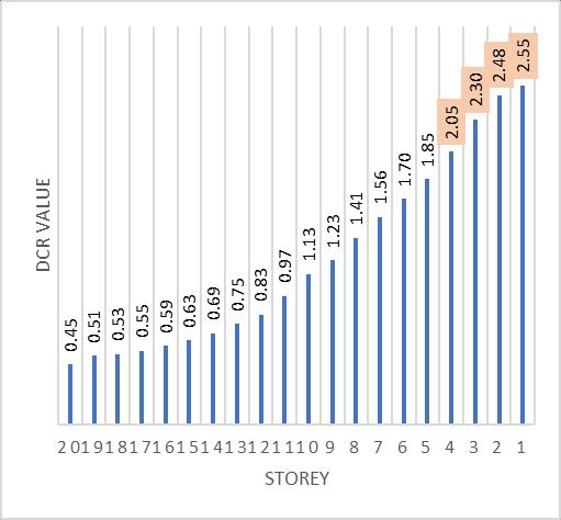
VariationsinDCRvaluesforthebeamsBeamB57 Structurewithoutriggerbeams
2022, IRJET | Impact Factor value: 7.529 | ISO 9001:2008 Certified
International Research Journal of Engineering and Technology (IRJET) e-ISSN: 2395-0056
Volume: 09 Issue: 08 | August 2022 www.irjet.net p-ISSN: 2395-0072
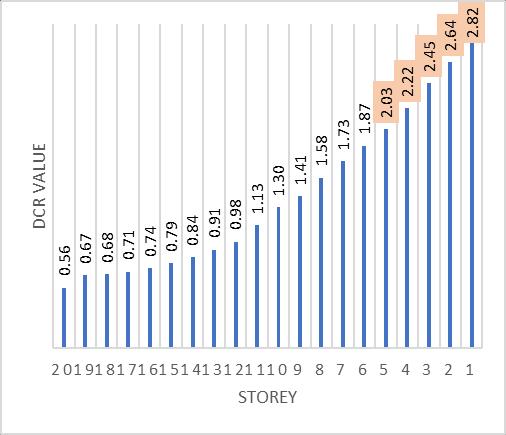
Chart -11:DemandCapacityRatioV/SstoreyofbeamB57
VariationsinDCRvaluesforthebeamsBeamB1
Structurewithoutoutriggerbeams
Chart -10:DemandCapacityRatioV/SstoreyofbeamB1
VariationsinDCRvaluesforthebeamsBeamB57
Structurewithoutoutriggerbeams
Chart -12:DemandCapacityRatioV/SstoreyofbeamB57
1. Case 1: Exterior column situated at the middle of theshortsideofthestructure.
i. Columnremovalatstorey1hasledtothe failureofadjacentbeamsB59&B60from storeys1to5andfailureofbeamB25from storeys 1 to 4 in case of structure with outrigger beams whereas in case of structurewithoutoutriggerbeams,failure of adjacent beams B59 & B60 is from storeys 1 to 14 and failure of beam B25 from1to17.
ii. Axial forces before and after column removal are compared for adjoining columns C46 & C48 and the percentage increaseisfoundtobe33.12%atstorey1 and 6.47% at storey 20 after column removal.
iii. Axial forces before and after column removal are compared for adjoining columnC15andthepercentageincreaseis foundtobe9.8%atstorey1and3.87%at storey20aftercolumnremoval.
iv. Inthiscase,whencolumnisremovedthe lengthofbeamsinthatbayisdoubledon eithersidesandhoggingbendingmoment is increased in tension zone resulting in increasingpositivereinforcement.
International Research Journal of Engineering and Technology (IRJET) e-ISSN: 2395-0056
Volume: 09 Issue: 08 | August 2022 www.irjet.net p-ISSN: 2395-0072
2. Case2:Exteriorcolumnsituatedatthecornerofthe structure.
i. Columnremovalatstorey1hasledtothe failure of adjacent beams B1 & B57 from storeys 1 to 4 in case of structure with outrigger beams whereas in case of structurewithoutoutriggerbeams,failure ofadjacentbeamsB1&B57isfromstoreys 1to14.
ii. Axial forces before and after column removal are compared for adjoining columnC37andthepercentageincreaseis foundtobe34.5%atstorey1and6.47%at storey20aftercolumnremoval.
iii. Axial forces before and after column removal are compared for adjoining columnC45andthepercentageincreaseis foundtobe35.16%atstorey1and6.12% atstorey20aftercolumnremoval.
iv. The beam members in both directions at thejunctionwherecolumnisremovedacts asanoverhangingcantileverbeamwhere load is transferred to adjacent structural members.
3. AccordingtoGSAthebeamswhoseDCRvaluesare morethanacceptancecriteriai.e.,2,thenthefailure of beams and columns will occur and is unsafe. If the DCR values are less than 2, it suggests that beamsandcolumnsaresafeasperGSA.
4. Whenacolumnisremoved,thecolumnabovethis column becomes a floating column and the moments&axialforcesaretransferredtoadjacent beamsandcolumnsfortheabovestoreys.
5. It is observed that the axial forces and bending moments are increased in load carrying elements adjacenttoremovedcolumnthereforetoovercome this, sizes of elements should be increased and bracingscanbeprovided.
6. Localizedfailureisobserveduptocertainnumber of storeys and failure at remaining stories is arrestedduetothepresenceofoutriggers.
7. Itwasobservedthatprogressivecollapseresisting capacityofstructurewithoutriggerbeamsishigher comparedtostructurewithoutoutriggerbeams.
8. Itisseenthatuseofoutriggerbeamsprovidesan alternateloadpathtothestructuretocompensate theimmediatelossofcolumn,thiscontributestoits
resistance to progressive collapse and provides timeforremedialmeasures.
I would like to thank K.L.S. Gogte Institute of Technology, Belagavi,Karnatakaforprovidingalltherequiredfacilities andspecialthankstofacultyforguidance.Iwouldalsoliketo thankalltherefereescitedinthispaper.
[1] General Services Administration (GSA), “Progressive collapse design guidelines for New Federal Office BuildingsandMajorModernizationProjectsJune2003”
[2] Osama Ahmed Mohamed and Omar Najm, “Outrigger Systems to Mitigate Disproportionate Collapse in BuildingStructures”,ELSEVIER,WorldMultidisciplinary Civil Engineering-Architecture-Urban Planning Symposium,pp.839-844,2016
[3] ZHANG Peng, CHEN Baoxu, “Progressive Collapse Analysis of Reinforced Concrete Frame Structures in Linear Static Analysis Based on GSA”, IEEE, Third InternationalConferenceonIntelligentSystemDesign andEngineeringApplications,pp.1074-1078,2012
[4] J. M. Mirhom, H.T. Hafez, K.N. Ibrahim, J.R. Shaker, M. Abdel-Mooty,“Progressivecollapseanalysisofahighrisebuildingconsideringtheeffectofanoutriggerbelt lateral load resisting system”, WIT Press, Structures UnderShockandImpactXII,pp.293-302,2012
[5] JinkooKim,JunheePark,“Progressivecollapseresisting capacityofbuildingstructureswithoutriggertrusses”, Wiley,Thestructuraldesignoftallandspecialbuildings, pp.566-577,2010
[6] HudaHelmy,HamedSalem,SherifMourad,“ComputerAidedAssessmentofProgressiveCollapseofReinforced Concrete Structures according to GSA Code”, ASCE, Journalofperformanceofconstructedfacilities,pp.529539,2013
[7] S.M.Marjanishvili,“ProgressiveAnalysisProcedurefor ProgressiveCollapse”,ASCE,Journalofperformanceof constructedfacilities,pp.79-85,2004
[8] Tae-SungEom,HiubaltMurmu,WeijianYi,“Behaviour andDesign ofDistributed Belt Walls asVirtual OutriggersforConcreteHigh-RiseBuildings”,Springer, IntJConcrStructMater,pp.1-13,2019
[9] Han-Soo Kim, “Optimum Locations ofOutriggers inaConcreteTallBuildingtoReduceDifferentialAxial Shortening”,Springer,KimIntJConcrStructMater,pp. 1-12,2018
International Research Journal of Engineering and Technology (IRJET) e-ISSN: 2395-0056
Volume: 09 Issue: 08 | August 2022 www.irjet.net p-ISSN: 2395-0072
DikshaD.Bhomkar M.Tech.StructuralEngineering StudentatK.L.S.GogteInstituteof Technology,Belagavi
Prof.KanchanB.Kanagali AssistantProfessoratK.L.S.Gogte InstituteofTechnology,Belagavi


2022, IRJET | Impact Factor value: 7.529 | ISO 9001:2008 Certified Journal