International Research Journal of Engineering and Technology (IRJET) e-ISSN: 2395-0056

Volume: 09 Issue: 08 | Aug 2022 www.irjet.net p-ISSN: 2395-0072
International Research Journal of Engineering and Technology (IRJET) e-ISSN: 2395-0056
Volume: 09 Issue: 08 | Aug 2022 www.irjet.net p-ISSN: 2395-0072
D. Umoh1, E.G. Ekpo2 , A. Akhikpemelo3
1Department of Electrical Electronics Engineering, Maritime Academy of Nigeria, 2Department of Electrical Electronics Engineering, AkwaIbom state Polytechnic IkotOsurua 3Department of Electrical Electronics Engineering, Maritime Academy of Nigeria, Oron ***
Abstract In the modelling and analysis of five-phase machine, the incorporation of the third-harmonics of the air-gap magneto-motive force during inductances determination help to improve the accuracy of the obtained results. Recording an increase in torque production as compared to neglecting the thirdharmonics. To representation the five-phase machine inductances takes more than a simple sinusoidal expression, as the magneto-motive force waveforms are non-sinusoidal. In utilizing the third harmonics of the air-gap magneto-motive force and avoiding transformation to a fictitious frame of reference, the direct-phase variable model (DPVM) is most suitable In the use of the DPVM, a phase dependent parameter is normally incorporated to present a near sinusoidal model. However, the use of the PDP is an approximation to satisfy a sinusoidal waveform, making it necessary to aspire for a model that avoids this approximation. This study models the five-phase synchronous reluctance machine considering utilizing the phase dependent parameter and ignoring the phase dependent parameter, with emphasis to the torque and speed characteristics of the machine at start, on load and during a loss of phase fault. The MATLAB/SIMULINK software is used for the analysis and implementation of the direct-phase variable model of the machine. Similar performance is recorded for the both models but with higher oscillation and transient percentage difference of 0.46%, 0.1 % and 2.4% at Start, loading and on fault respectively with the PDP model for the Speed Characteristics.
magnetic reluctance is determined by the number of employed phase especially in the multi-phase system. A synchronous reluctancemachine(SYNRM)hasanidentical statoras the induction motor but witha salient pole rotor, and similar principle of operation as the salient pole synchronous motor, but with modifications in the number ofdamperwindings.For improvedaccuracy,a multi-phase machine,thewindingfunctionismodelledtoresemblethe actual waveform of the winding in the slots, as well as it suppliedpower.
TheFiniteElement(FE)methodisknowntoyieldaccurate result, but involves detailed characteristics machine studied, nevertheless, the winding function (WF) method yield accurate result that can be compared to the finite element (FE) method [1-3], while avoiding detailed machinecharacteristicsstudy Due tothe requirement ofa smallair-gapforagoodsaliency,theperfectdistributionof winding in sinusoidal form in the stator periphery cannot accurately describe the process [1], thus it is of great necessity to model the actual form of the winding with minimalerror.
For a simple sinusoidal expression, the representation of inductances is less complicated as seen in three-phase synchronous machine [2, 4], and as compared to higher multi-phase synchronous machine due to the accommodationofthehigherharmonics[5-9].
Forthefive-phasemachinetoachieveanaccurateresult,a true representation of the turn and winding function, accommodating the third-harmonics of the air-gap MMF is necessary.
Sncronous Reluctance, Five-phase, Phase variable model, Phase dependent parameter
For a synchronous reluctance machine, the reluctance torqueisnecessaryforenergyconversion,asachievingthis dependsonahighsaliencyratiobetweenthed-axisandthe q-axisinductances.
The inductance ratio between the two magnetic directions (q-axisandd-axis)oftherotorcreatesamagneticpotential betweentheseaxes,whichinturndeterminesthestrength of the produced torque. The axis with the maximum
Neglecting the harmonics, the multi-phase inductances resemble the three-phase inductances, and are just a resemblance of the inductances with significant recorded error.
The accuracy recorded in the use of the winding function and the modified winding function approaches [10], to verifyingtheequalityofthemutualinductances,hadreduce the work load in inductance determination. The Taguchi design of experiment methodology, with optimization of each rotor parameters using analysis of variance [11, 12] wasemployedforrotorparameteroptimization.
International Research Journal of Engineering and Technology (IRJET) e-ISSN: 2395-0056
Accommodating the third-harmonics of the air-gap MMF [7],anacceptableresultwasobtained,evidentinincreased torqueproductionvalidatedbyexperimentalprocess.
Despite accommodating the third harmonics of the air-gap MMF[7],thestatorinductancewastransformtoafictitious frame of reference instead of using the developed winding function directly thus minimizing assumption [2]. To represent these five-phase stator inductance, phase dependent co-efficient (PDP) was introduced [6], but did not account for the air-gap MMF third- harmonics accommodate. Reference [15] accounted for the thirdharmonics of the air-gap MMF, validated the result by the use of FE method, but still employed the use of phase dependent co-efficient, thus giving a near sinusoidal representationofthestatorinductanceascomparedtothe actualwaveform
This study models a five-phase synchronous reluctance machineaccommodatingthethirdharmonicsoftheairgap MMF and avoids the use of a PDP, while considering the machinecharacteristicperformanceofspeedandtorqueat start, synchronism, on load and loss of e-phase fault, comparing with the model using PDP accommodation the third-harmonicsoftheair-gapMMF.
The voltage equation for a five-phase synchronous reluctancemachine(SYNRM)isgivenin(1)
( ) ( { ( )} ) (1) (2) [ ] (3)
[ ] (4)
where istherotorposition.
and are the machine current and voltage matrices and aregivenin(3)and(4)respectively.Theinductancematrix isgivenin(5).
( ) [ ( ) ] (5)
Where, [ ] (6)
[ ] (7)
[
( ) ( ) ( ) ( ) ( ) ( ) ( ) ( )]
(8)
Where is the stator inductances matrix, is the rotor inductances matrix referred to the stator and is the mutual inductances matrix between the stator and the rotor referred tothestator, is the rotorq-axisleakage inductancereferredtothestatorand istherotord-axis leakageinductancereferredtothestator. [ ]
(9)
R is the resistance matrix. The electromagnetic torque is givenin(9) ( ) ( ) (10) [ ] (11) [ ] (12) ( ) (13)
Where, is the stator current matrix and is the rotor current matrix.
Jistheinertiaexpressedinkilogram-metersquare( ) orjoule-secondssquare( ),whilepisthenoofpolesof themachine.
Using the expression for the calculation of stator inductances[14],andaspresentedin(14).
∫ ( ) ( ) ( ) (14)
Where ( ) and ( ) are the winding functions of phase X and Y respectively and φ is the stator circumferential position. ( ) is the inverse air gap
Volume: 09 Issue: 08 | Aug 2022 www.irjet.net p-ISSN: 2395-0072 © 2022, IRJET | Impact Factor value: 7.529 | ISO 9001:2008 Certified Journal | Page1971
International Research Journal of Engineering and Technology (IRJET) e-ISSN: 2395-0056
Volume: 09 Issue: 08 | Aug 2022 www.irjet.net p-ISSN: 2395-0072
function which is a function of the stator circumferential position( )andtherotorposition( ),whilelistheaxial length of the air gap of the machine, r is the radius to the meanoftheairgapand isthepermittivityoffreespace. The inverse air-gap function including the third harmonic componentisgivenin(15).
( ) ( ) ( )(15)
Where, ( ) (16) ( ) (17)
Where is the main air gap length, is the inter-polar slotspaceandβistheratioofpolearctoslotpitch.
For self-inductances, equation (19) will be of the form of (18).
∫ [ ( )] ( ) (18)
It is observed that the stator mutual inductance has a general sinusoidal approximation form of the inductances asgivenin(19).
( ) (19) (20) (21)
Where , arethephasedependentparameter,and dependsonthephaseshift
Where v takes the form of 0, 1 or 2, giving a phase dependent value of ( ), ( ) or ( ) respectively
The phase dependent parameter values of choice give rise tothreemodelsofanalysis;withthirdharmonicoftheairgapMMF,neglectingthethirdharmonicoftheair-gapMMF andasinusoidalapproximationformula[6].
To represent the stator winding inductances in a generalized equation, the models can be adopted as variationoftheactualrepresentation.
Fromageneralizedequationofinductances[6], (22)
Wheretheexpressionfor and aregivenin(23) and(24)respectively.
[ ] (23)
The q-axis and the d-axis magnetizing inductances are givenin(25)and(26)respectively.
( ) (25) ( ) (26)
Where, ( ) (27)
IgnoringtheuseofthePhase DependentCoefficient (PDP), a direct phase variable model of the machine accommodatingtherotorinductancescanbedevelopedby adapting the works of [5]and [6], and are given in (28) to (34).
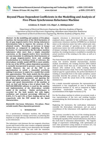
The relationship between the windings are represented in figure1.
Fig.1:5-phasemachinewindingsshowingthemutual couplingasseenintherotord-qcircuits
Infigure1,thestatorwindingsofthephasesareconsidered as utilizing the fundamental and the third harmonics of MMF.
[ ] (28)
International Research Journal of Engineering and Technology (IRJET) e-ISSN: 2395-0056
Volume: 09 Issue: 08 | Aug 2022 www.irjet.net p-ISSN: 2395-0072
( ) ( ) ( ) ( ) ( ) ( ) ( ) ( )]
(29) [
RatioPolearc/Polepitch ⁄ Numberofpoles 4 Frequency 50Hz
[
( ) ( ) ( ) ( ) ( ) ( ) ( ) ( )]
(30) [
( ) ( ) ( ) ( ) ( ) ( ) ( ) ( )]
(31) Where (32) (33) (34)
The considered five-phase SYNRM design parameters are givenintable1.
TABLE I. SYNRMMACHINEDIMENSIONSANDCIRCUIT PARAMETERS
5-phaseSRM
Quantities Value
StatorOuter/innerradius 105.02/ 67.99mm
RotorRadius 67.69mm
Effectivestacklength 160.22mm
Numberofslot 40
Numberofturns 64
Mainair-gaplength 20.4mm
Interpolarslotspace 21.3mm
Statorslotdepth 18mm StatorSlotpitch
Thestatorresistance 0.83Ω Statorleakageinductance 10.98mH rotorq-axisleakage inductance 6.2mH, Rotorq-axisleakage inductance 5.5mH Rotorq-axisresistance 0.25Ω rotord-axisresistance 0.12Ω momentofinertia J 0.089kg/m2 phasevoltage 370v
2022, IRJET | Impact Factor value: 7.529 | ISO 9001:2008 Certified Journal | Page
International Research Journal of Engineering and Technology (IRJET) e-ISSN: 2395-0056
Volume: 09 Issue: 08 | Aug 2022 www.irjet.net p-ISSN: 2395-0072
[
( ) ( ) ( ) ( ) ( ) ( ) ( ) ( ) ( ) ( ) ( ) ( ) ( ) ( ) ( ) ( ) ( ) ( ) ( ) ( ) ( ) ( ) ( ) ( ) ( )] (24)
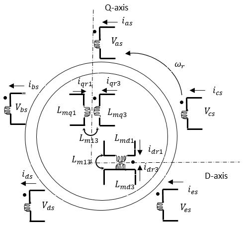
Fig.2.5-phstatorself-inductances
The modelled 5-ph Synchronous Reluctance Machine is started directly on-line, loaded at 2.5 seconds with a load torqueof10N-maftersynchronism.At4seconds,alossof e-phase fault was created and subsequently restored after a second. Investigation of the machine characteristics of torqueandspeedwasdocumentedandcomparedforboth thephasevariablemodelsofusingaPDP(modelI)andnot usingPDP(modelII).
The speed characteristics of the models are presented in Fig. 3, with the Fig.4 and Fig.5 showing the transient at start and loading respectively. Fig.6 and Fig.7 shows the transientonstartofe-phasefaultandonrestorationofthe e-phasefaultrespectivelyforbothmodels.
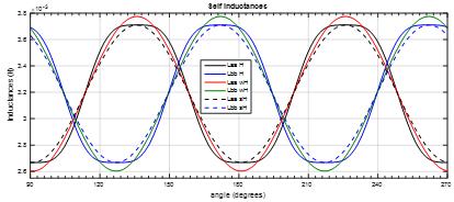
At start, the Speed performance characteristics shows a higher transient rise of 321.4 rad/s for model I as compared to 345.4 rad/s for model II, thus recording a 38.96%oscillationformodelIascomparedto18.24%for modelII.
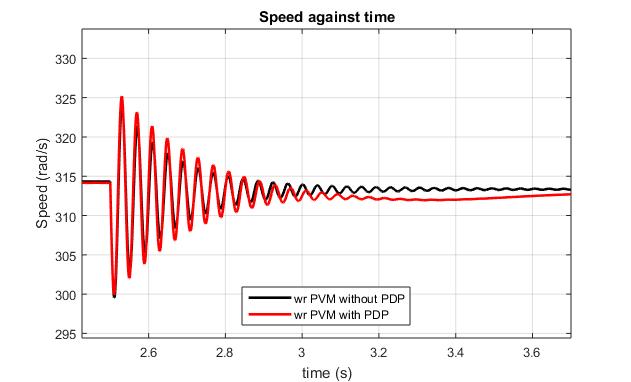
On loading, model I speed characteristics show a higher percentage oscillation of 8.09 % about the synchronous speed as compared to 7.99 % for model II. It can be observed that the maximum transient recorded for the difference in speed characteristics between the models on loadingis0.1%.
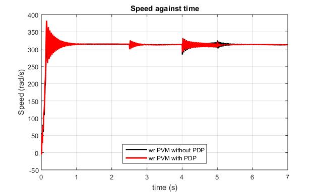
At loss of e-phase fault, a lower Speed oscillation rise of 12.83 % about the synchronous speed is observed for model I as compared to 15.25 % rise for model II, recording a percentage difference of 2.4 % between the modelsatfault.
Fig.3.SpeedCharacteristics
Fig.4.SpeedCharacteristics(Transientatstart)
2022, IRJET | Impact Factor value: 7.529 | ISO 9001:2008 Certified Journal | Page1974
International Research Journal of Engineering and Technology (IRJET) e-ISSN: 2395-0056
Volume: 09 Issue: 08 | Aug 2022 www.irjet.net p-ISSN: 2395-0072
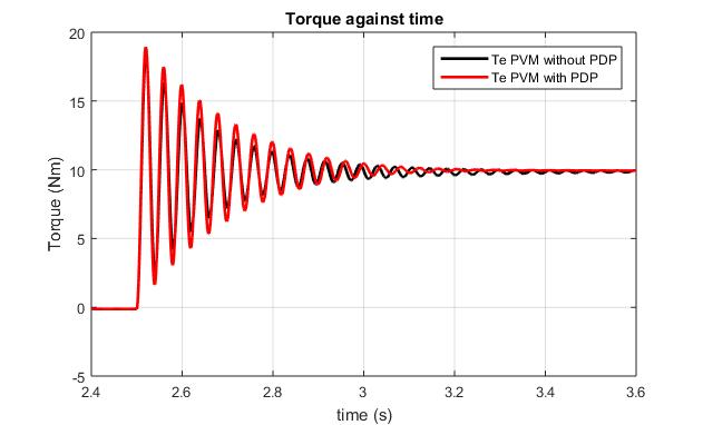
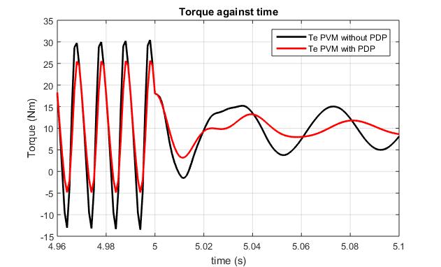
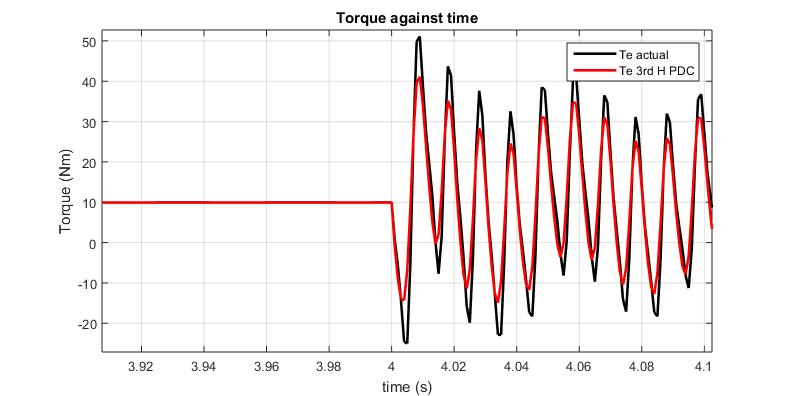
On loading, model I torque characteristics show a torque transientdifferenceof2.69%inmaximumoscillationvalue between the models. A greater value for the difference in minimumtorqueonloadingis31.95%betweenthemodels.
At loss of e-phase fault, a lower Speed oscillation rise between the models is 19.52 % while the minimum rise betweenthemodelsis42.91%.
Fig.5.SpeedCharacteristics(TransientatLoading)
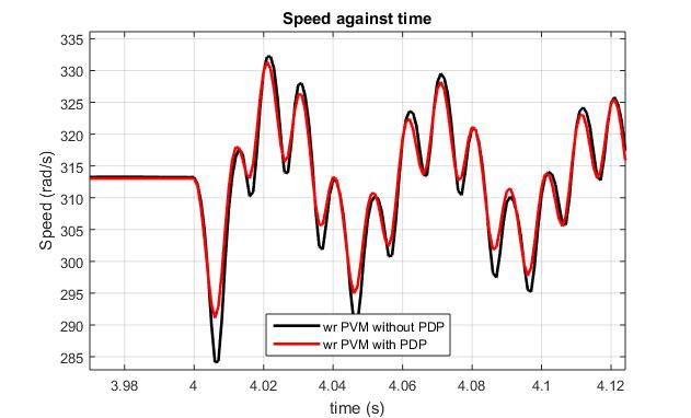
Fig.6.SpeedCharacteristics(TransientatLossofe-Phase initiated)
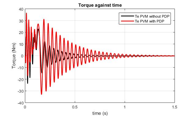
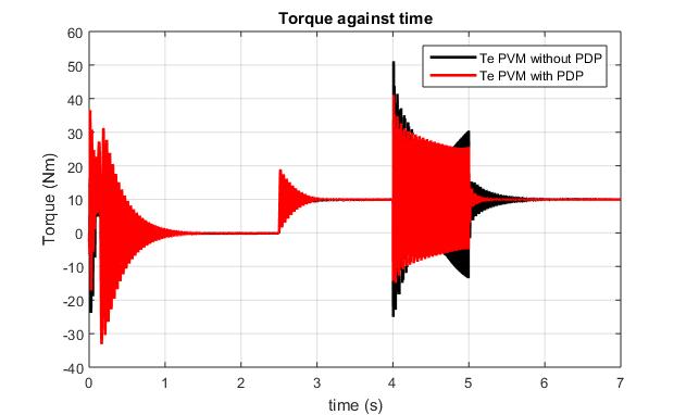
Fig.8Torquecharacteristics(WithandWithoutPDP)
Fig.9. Torquecharacteristics(Transientatstart)
Fig.7.SpeedCharacteristics(TransientonrestorationofePhase)
TheTorquecharacteristicsofthemodels(Fig.8),transient at start (Fig.9), transient on loading (Fig.10), transient on the start of e-phase fault (Fig.11) and subsequent restoration of the e-phase fault (Fig. 12) present a comparativeplotsofthemodels.
At start, the torque transient performance characteristics formodelIhavingavalueof 36.59Nmvalueshowgreater rise ascompared to 29.71 Nm for model II, thus recording an 18.8 % difference in maximum oscillation between models at start. Similarly, minimum transient rise of33.14NmisobservedinmodelIascomparedtoa-23.81Nm valueriseformodelII,thusrecordinga28.15%difference fortheminimumtransientriseatstart.
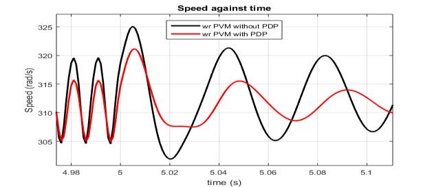
Fig.10. Torquecharacteristics(Transientatloading)
An enlarge view of the plot of the torque characteristics before loading after synchronous speed is attained is presented in Fig. 10, while the plot of the torque
International Research Journal of Engineering and Technology (IRJET) e-ISSN: 2395-0056
Volume: 09 Issue: 08 | Aug 2022 www.irjet.net p-ISSN: 2395-0072
characteristics onstartoffaultandsubsequentrestoration ofe-phasearepresentedFig.11andFig.12respectively.
(N-m)
PVM(PDP) 36.59–33.14 18.94–1.64 41.16–14.29
PVM WithoutPDP 29.71–23.81 18.43–2.41 51.14–25.03
To a greater percentage, the period between the models during transient is constant despite the change in oscillationsvalueasshowninFig.13.
Fig.11. Torquecharacteristics(atstartoflossofe-phase fault)
Both models of utilizing the phase dependent coefficient andnotincorporatingthephasedependentparameterstill settles at the synchronous speed even though the settling times varies between the models. The model without PDP settlesaftertransientatstartat1.3secondsascomparedto a recorded value of 1.97 seconds for the model utilizing PDP.
Fig.12. Torquecharacteristics(Torqueoscillationsduring lossofphaseandsubsequentrestoration)
The performance characteristics of the different models of withoutPDPandPDPofspeedandtorquearetabulatedin tableIIandtableIIIrespectively.
TABLE II. SPEEDPERFORMANCE CHARACTERISTICS
Speed Characteristi
cs (rad/s)
Start Loading Fault Transient(m ax–min) Transient(m ax–min) Transient(m ax–min)
PVM(PDP) 382.4-260 325.2–299.8 331.4–291.1
PVM WithoutPDP 345.4–288.1 324.6–299.5 332.2–284.3
TABLE III. T
Torque Characteristi
cs
Start Loading Fault Transient(m ax–min) Transient(m ax–min) Transient(m ax–min)
Fig.13Speedperformancecharacteristics(speed fluctuationsduringlossofphase)
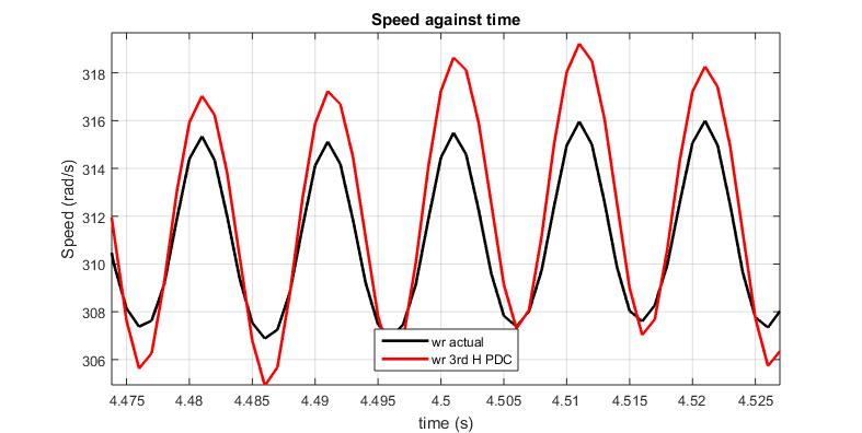
The effect of the third harmonic component of the air-gap MMF has been accommodated in both models, but when utilizing the phase dependent parameter, a higher percentage of oscillation is observed as compared to the model without phase dependent parameter. percentage difference in transient of 0.46%, 0.1 % and 2.4% at Start, loading and on fault respectively with the PDP model for theSpeedCharacteristics.Bothmodelshavethesamevalue at synchronism before loading and after the loss of phase faultisrestored.DespiteobservedoscillationinmodelPDP, ittakeslongertimetosettleatstartbutlessersettlingtime on loading, as compared to observation with the model without PDP. On restoration of the loss of phase fault, an increase in phase shift is observed with the PDP model having a shift of for the first out of phase oscillation, anddampedfasterascomparedtothewithoutPDP.
International Research Journal of Engineering and Technology (IRJET) e-ISSN: 2395-0056
Volume: 09 Issue: 08 | Aug 2022 www.irjet.net p-ISSN: 2395-0072
Considering the observed oscillations, variance in amplitudeisbetweenthemodelsastheangleofoscillation is maintained. This is an indication that the PDP model, while presenting an approximation of the stator inductancesinasinusoidalform,introducedanincreasein the value of the amplitude. The PDP model gives an acceptable result but a more accurate result is given with themodelthatneglecttheuseofthePDP.
[1] E. Obe, “Calculation of inductances and torque of an axially laminated synchronous reluctance motor,” 2010, IET Electr. Power Appl., vol. 4, no. 9, pp. 783792.
[2] E.ObeandA.Binder,“Direct-phase-variablemodelofa synchronous reluctance motor including all slot and winding harmonics,” Energy Conversion and Management,Vol.52pp284-291.2011.
[3] E. Obe, “Direct Computation of AC machine Inductances based on winding function Theory,” Energy Conversion and Management, vol. 50, pp 539542,2009.
[4] P. Krause, O. Wasynczuk and S. Sudhoff, Analysis of ElectricMachinery,NewYork,IEEEpress,1995.
[5] H. Toliyat, S. Waikar andT.Lipo, “Analysis and Simulation of Five-Phase Synchronous Reluctance Machine Including Third Harmonic of Airgap MMF,”IEEE Trans. on Ind. Application, vol. 34, no. 2, pp.332-339,1998.
[6] T. Camarano, T. Wu, S. Rodriguez, J. Zumberge and M. Wolff “Design and Modeling of a Five-Phase Aircraft Synchronous Generator with High Power Density,” IEEE Energy Conversion and Exposition (ECCE), pp. 1878 – 1885, 2012.R. Nicole, “Title of paper with only first word capitalized,” J. Name Stand. Abbrev., in press.
[7] H. Toliyat, M. Rahimian, and T. Lipo, “DQ Modeling of FivePhaseSynchronousReluctanceMachineIncluding Third Harmonic of Air-Gap MMF,” IEEE Industry
Applications Society Annual Meeting, vol. 1, pp 231237, Sep/Oct 1991.M. Young, The Technical Writer’s Handbook.MillValley,CA:UniversityScience,1989.
[8] G. Umoh, and E. Obe, “Five-Phase Synchronous ReluctanceMotor:Abetteralternativetothethreefive Synchronousmotor,”ICEPENG,pp.56-61,Oct.2015.
[9] G. Umoh, and E. Obe, “Analysis of Five-Phase Synchronous Reluctance Motor under loaded and faultedconditions,”ICEPENG,pp.37-43,Oct.2015.
[10] Toliyat,H.,Nandi,S.,Choi,S. et al.:‘Electrical Machines Modelling,ConditionMonitoring,andFaultDiagnosis’, CRCPress,Taylor&FrancisGroup,2013.
[11] H. Azizi and A. Vahedi, “Sensitivity Analysis and Optimum design for the Stator of Synchronous Reluctance Machine using the coupled finite and Taguchi method,” Turkish Journal of Electrical and ComputerSciences,vol.23pp38-51,2015.
[12] H. Azizi and A. Vahedi, ‘Rotor Geometry Parameter Optimization of Synchronous Reluctance Motor using Taguchi Method’, Przeglad Elektrotechniczny, vol. 89, pp127-201,2013.
[13] L. A. Pereira, C C. Scharlau, L. F. A. Pereira and S. Haffner “Influence of Saturation on the Airgap Induction Waveform of Five-Phase Induction Machines,” IEEE Transactions on Energy Conversion, vol.27,no.1,pp29-41,2012.
[14] N. Schmitz and D. Novotny,Introductory Electromechanics, New York, The Ronald Press Com., 1965.
[15] G. D. Umoh, E. S. Obe and O.I. Okoro, “The Effect of Third-Harmonics of the Air-gap MMF on Inductance Determination in five-phase Synchronous Reluctance Motor,” IEEE 3rd Conference on Electro-Technology for National Development (NIGERCON), pp. 795801,2017.