International Research Journal of Engineering and Technology (IRJET) e-ISSN: 2395-0056

Volume: 09 Issue: 08 | Aug 2022 www.irjet.net p-ISSN: 2395-0072
International Research Journal of Engineering and Technology (IRJET) e-ISSN: 2395-0056
Volume: 09 Issue: 08 | Aug 2022 www.irjet.net p-ISSN: 2395-0072
2
1M.Tech scholar, Electrical and Electronics Department, SSTC Bhilai, Chhattisgarh, India 2Professor ,Electrical and Electronics Department, SSTC Bhilai, Chhattisgarh, India ***
Abstract - This paper presents modeling and simulationfor the design of a hybrid micro grid system with renewable energies and methods for their control, resulting from the analysis. The photovoltaic installation includes photovoltaic panels and a DC-DC boost converter. The boost converter connected to the photovoltaic station was controlled using an additional maximum Power Point tracking and using incremental conductance algorithm (IC-MPPT A). The conversion element for boost convertersisIGBT. Theswitching frequency of the boost transformer is 50 kHz for the photovoltaic array connected to the boost transformer. The hybrid micro grid was paired with a 1000V DC bus. A 400 V / 120 kV transformer and a 120 kV and 50 Hz AC power supply were used to create the network model. To convert DC to AC, as a topology, a full bridge inverter circuit was used and IGBT was chosen as the switching element. The phase closed loop (PLL) algorithm was used as a control so that the alternating current voltage generated at the output of the inverter is of the same phase, frequency and amplitude as the network. The system was operated under sunlight. Despite these variables, the desired results were obtained from the system.
Key Words: DC-DCBoostConverter;IC,MPPTtechniques; PV array model; Three Phase Three-Level Inverter, IGBT, PLL.
The increasing demand for energy particularly in developingcountrieslikeIndiaandChinaanddepletionof fossil fuel reserves has pushed all countries to finding alternativesourcesofenergy.Thoughwearehavingmany alternative sources of energy, solar PV and wind are the widelyusedenergyresources[1].APVsystemconsists of manycomponentssuchasPVmodules,mountingstructure and electrical connections and means of regulating and modifyingtheelectricaloutput.Asweknowsolarcells,when exposedtosolarradiation,produceDCpowerwhichhasto be converted to AC power using power electronics-based convertersalongwithcontrolequipment’s[2].Mostofthe PVinvertersarevoltage-sourceinvertersastheyaresimple havebothvoltageandcurrentloopswithgoodstability,very fast response. These are easy to implement and have inherentabilitytocontrol bothvoltageandcurrent.The modeling and simulation of 100 kWp photovoltaic Power SysteminstalledandoperatingatG.
NarayanammaInstituteofTechnology&SciencesinceMarch 2014.Thisgrid-connectedPVsystemconsistsofPVarrays installedontheroof-topterracesoftwoofthebuildingsin thecollege.
The photovoltaic panels are connected to the distribution boardsofthebuilding concernedby five20kWinverters. [3]-[4]. The simulation was carried out using the mathematical model for 20 kW photovoltaic panels. Two popularMaximumPowerPointTracking(MPPT)algorithms forcapturingthemaximumpossiblepowerunderdifferent solar irradiance conditions on the MATLAB/Simulink platform [5]. The two MPPT algorithms used viz. The (1) Perturb and Observe (P&O) and (2) Incremental Conductance (IncCond) algorithms are included in the control strategies used in the DC-DC boost converter connected between the PVarrayandtheinverter[6].The resultsofthesimulationoftheoutputpowerandothersolar radiation variation parameters were compared with the actual power measurements made at the corresponding irradiancelevels.
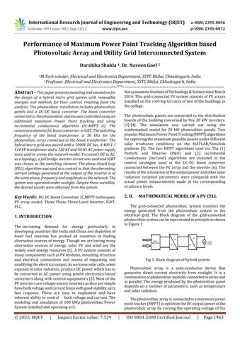
The grid-connected photovoltaic system transfers the energy generated from the photovoltaic system to the electrical grid. The block diagram of the grid-connected photovoltaicsystemcanberepresentedinprincipleasshown inFigure1
Photovoltaic array is a semi-conductor device that generates direct current electricity from sunlight. It is a combinationofphotovoltaicmodulesconnectedinseriesand inparallel.Theenergyproducedbythephotovoltaicpanel depends on a number of parameters, such as temperature andsolarradiation.
Thephotovoltaicarrayisconnectedtoamaximumpower pointtracker(MPPT)tooptimizetheDCoutputpowerofthe photovoltaic array by varying the operating voltage of the
International Research Journal of Engineering and Technology (IRJET) e-ISSN: 2395-0056
Volume: 09 Issue: 08 | Aug 2022 www.irjet.net p-ISSN: 2395-0072
photovoltaic array. The direct current power is then converted into alternating current by an inverter before beingroutedtotheelectricitygrid.
AnequivalentcircuitofasolarcellisshowninFigure2[1] whichcanberepresentedby(1).
Thediodeimprehgnationcurrent,Iowhichdependson temperatureisgivenby(3)[2]. 0 exp1
Where:
Where:
Iph=thesolar-generatedcurrent.
Io=isthediodesaturationcurrent.
Vt = NskT/q is thermal voltage of thearray.
Ns= number of cells connected in series.
a=idealityconstantofdiode.
Rs=series-resistance.
Rp=parallel-resistance.
The current generated by the sun, Iph, is linearly dependent on solar radiation and is influenced by temperaturedependingonthe(2)[1]. ()phphnin n
G IIKTT G (2)
where
Iph,n = Solar initiate current at the nominal-condition (25°Cand1000W/m2); G=irradiance;
Gn=nominalirradiance; T=celltemperature;
Tn=nominalcelltemperature;
Ki=short-circuitcurrent/temperaturecoefficient.
Io=nominaldiodesaturationcurrent. q=1.602*10-19C (electroncharge). k=1.380*10-23J/K (Boltzmannconstant). Eg=1.12eVisthebandgapenergy. Thenominaldiode 3 0 11 exp g an
Vocn=nominalopen-circuitvoltage; Vt,n =nominalthermalvoltageofthecell; Isc,n =short-circuitcurrentatthenominalcondition (25oCand1000W/m2).
A practical photovoltaic panel consists of several switchedphotovoltaicmodulesconsistingofNssolarcells connected in series and in parallel. Therefore, (1) with a singlePVcellshouldbereplacedwith(5)torepresentaPV generator.[2],[3].
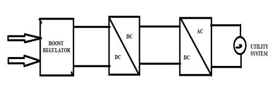
Figure 3 below shows a boost or pulse width modulated (PWM)converter.ItconsistsofaDCinputvoltagesourceVg, acontrolledswitchS,adiodeD,aboostinductorL,afilter capacitorCandaloadresistorR.
Fig3: Circuitdiagramorboostconverter
International Research Journal of Engineering and Technology (IRJET) e-ISSN: 2395-0056
Volume: 09 Issue: 08 | Aug 2022 www.irjet.net p-ISSN: 2395-0072
Fromtheinductorvoltagebalanceequationwehave
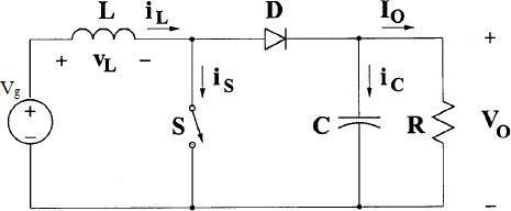
In practice, the photovoltaic generator is connected to theMPPT sothat the photovoltaicgeneratorcan produce themaximumpoweritiscapableofbyvaryingtheelectrical operatingpointofthephotovoltaicgenerator.TheMPPTis basically a DC-DC converter as shown in Figure 3. The converter changes the operating voltage level of the PV array so that it can operate at Vmp to produce maximum power.Theoperatingvoltageleveliscontrolledbychanging the duty cycle of the inverter. A pulse-width modulation (PWM)controlsignalisappliedtothegateofthetransistor intheDC-DCconverter,asshowninFigure3.Analgorithm automaticallycontrolsthegenerationofthePWMcontrol signal.TheHillClimb(HC)algorithmisusedtocontrolthe dutycycleoftheconverter.Figure4showstheflowchartof theHCalgorithm[9].Intheproposedalgorithm,thecurrent andthevoltagedrawnfromthephotovoltaicnetworkare measured and the power calculated. The 'slope' is the disturbancedirectionofthedutycycleDwithvaluesof'1'or '-1'and'a'istheamplitudeofthedisturbancestep.When thepowerincreases,thedirectionofthedisturbanceofthe duty cycle remains in the same direction until the MPP is reached,onthecontrarywhenthepowerdecreases.
minimizingthesizeofthedisturbance.Theorganizational chartforP&Oisshowninfig.3,wherethechangeinvoltage attheterminalsofthephotovoltaicgeneratorisresponsible forthechangeindutycycle.
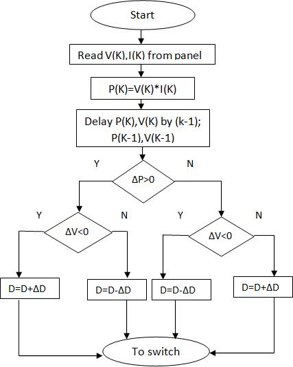
The P&O method works by periodically increasing or decreasing the voltage or current of the photovoltaic generatorbycomparingtheoutputpowerP(n+1)withthe previousvalueofthepowerP(n).Ifthevoltagedisturbance at the terminals causes a power increase greater than (dp/dv=0) then the disturbance must remain in the same directionormoveintheoppositedirection.Thisbreakdown cyclemustberepeateduntilmaximumpowerisreached.
Manyalgorithmshavebeendescribedintheliterature to determine the maximum power of the photovoltaic system. Two of these methods, the P&O and IncCond methods, which have good convergence speed and less complexity,areusedinoursimulation.
ThemostrecommendedmethodistheP&Omethoddue toitssimplicityandeaseofimplementation.Inthismethod, the failure is in the operating voltage of the photovoltaic generator.SincetheP&Oalgorithmcannotcomparethegrid terminal voltage to the actual maximum supply point voltage,thechangeinpowerisassumedtobetheresultof the grid terminal voltage disturbance. The output of this method exhibits oscillations which can be reduced by
Fig.5.FlowchartofP&Omethod
UsuallyanyconventionalMPPThastwoindependent controlloopsformaximumpowercontrol.Thefirstloop containsthealgorithmandthesecondloopcontainsthe proportional-integral (PI) controller. This method uses incrementalconductiontogeneratetheerrorsignalwhich will be zero at full power. Usually this error will not be zero, so it is up to the second control loop to make this errorzero.DuetothenonlinearcharacteristicsofthePV output and the unpredictable behavior of PI weather controllers, they do not perform well. Therefore, in this article,preferenceisgiventotheincrementalconductance method,whichexertsdirectcontrol.Herethedutycycleis adjusteddirectlyfromthealgorithm.Tocompensatefor the lack of PI, we allow a marginal error of 0.002. This allowable error size determines the sensitivity of the

International Research Journal of Engineering and Technology (IRJET) e-ISSN: 2395-0056
Volume: 09 Issue: 08 | Aug 2022 www.irjet.net p-ISSN: 2395-0072
system. The maximum power consumption condition is (dI/dV=-I/V).TheIncCondflowchart.Thedirectcontrol method is shown in Fig. 4. According to the MPPT algorithm, the duty cycle is calculated and used as the desireddutycycleforthenextstep.
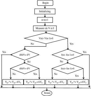
Fig 6 : Flow Chart of Incremental Conductance
Here we use a three-phase three-level inverter because it provides industrial applications through adjustable frequencypower.Theinverter'sDCpoweristakenfromthe largecapacitorconnectedtotheinputterminaltosuppress harmonic feedback to the source and make the DC input constant. The inverter is neutral point clamped (NPC) to have higher voltage and reduce current ripples in the waveformbyincreasingthenumberofsteps.
The three-phase voltage source converter regulates theDCbusvoltageupto500voltswhilemaintainingthe power factor of one. Here, the control system uses two controlloops:anouterlooptocontroltheDCbusvoltage to+/- 250voltsandan innerloop tocontrol theactive current component (Id) and the reactive current component(Iq)onthenetworkside..Thecontrolsystem usesa100µssamplingperiodforthecurrentandvoltage regulators.
Themajorfunctionsofthegridsidecontrollerare:
Gridsynchronization
Ensure acceptable power quality at the grid interfaceunit
Control of reactive power transfer between the gridandconverter
Controlofactivepowerinjectedintothegridand tomaintainconstantDClinkvoltage
Here the control strategy involves two cascaded loops: The first is a fast internal current loop for maintaining sinusoidalcurrentsandtoprotectagainstovercurrents andthesecondisanexternalvoltagesloopforbalancing thepowerflowinthesystem.
InSimulinkvariousPVarrayarepresentandinproposed systemSunPowerSPR305WHT-Disconsidered.
Parameters Values
NumberofcellperModule 5
Numberofparallelstring 66 Voc 64.2V Vmpp 54.7V Impp 5.96A
Inthispapermodelingandsimulationofa100kWpsolar PV power plant has been done. MPPT method have been employedandithasbeenobservedthatthegeneration of powerincreaseswithincreaseinirradiance.
InthispaperwepresentthemathematicalmodelingofPV anditsIVcharacteristicsbyMATLABR2020asoftware.This paper suggests that MPPT algorithm can be enabled with boost converter circuit so as to get better results with PV modules so as to get continuous supply with a PV grid integratedsystem.Theoverallcontrollinginputparameter for generating power with PV module is temperature and irradianceandithasbeenseenthatthegeneratedPVpower is inversely proportional to the temperature whereas it is directly proportional to the irradiance level measured in w/m.
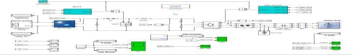
Fig7:SimulationModelofHybridMicrogridbasedonMPPT
International Research Journal of Engineering and Technology (IRJET) e-ISSN: 2395-0056
Volume: 09 Issue: 08 | Aug 2022 www.irjet.net p-ISSN: 2395-0072
After t=2.1s the duty cycle starts increasing and again reachestoitsmaximumvalueof.5.
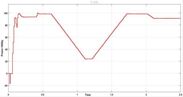
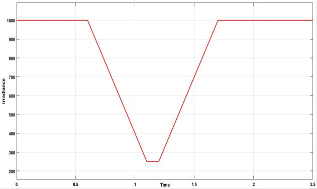
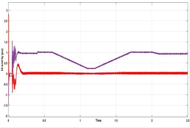
Figure10showsthedirectandquadraturecurrentper unit values for the designed model.Id and Iq attains its maximumvalueof1.5puattimet=0.1s.
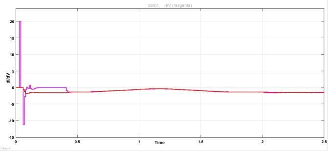
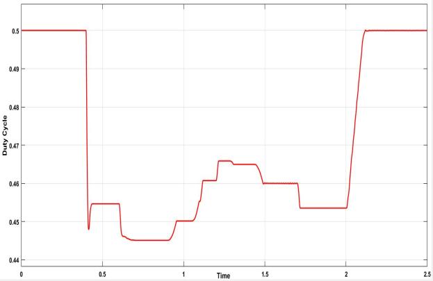
Fig8:CurrentAtBus
Fig11showstheinputofirradiancetoPVmodules. Theirradiancelevelreachesahighestvalueof1000w/mas shown in figure. At time t=.6sec the irradiance level start droppingandreachestoavalueof250w/matt=1.1sbut aftert=1.2sitstartincreasinggraduallyandfinallyattainsit maximumvalueof1000w/matt=1.7s.
In figure 8 shows Current at the bus has been seen changing accordingly with the change in pattern of irradianceprovided.
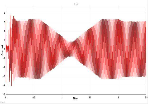
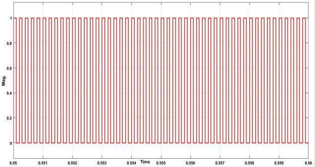
Fig.shows9 thedutycycleappliedtoconverterwhose maximum value is .5.At t=.4s the applied MPPT algorithm getsenabledand startsregulatingtheconverter’sdutycycle soastoextractthemaximumpowerfromPVmodule.
Fig12:MPPTalgorithmdi/dv
Fig13:PowerUtility
International Research Journal of Engineering and Technology (IRJET) e-ISSN: 2395-0056
Volume: 09 Issue: 08 | Aug 2022 www.irjet.net p-ISSN: 2395-0072
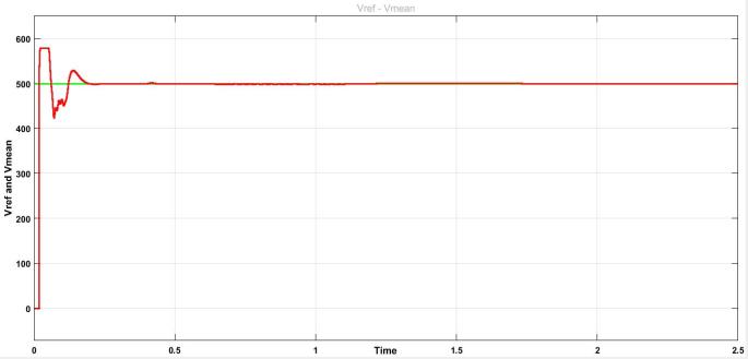
Meanvoltageforinvertercircuitisshownbelowinwhich thereferencevalueissetat500Vwhereasthemeanvalue reaches its maximum value of 508V within fraction of secondsfrom0.
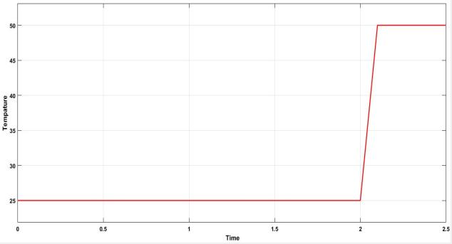
Fig15showsthetemperaturevariationappliedatthe inputofthephotovoltaicmodule.Thetemperatureis25˚Cat t=2sthenreaches50˚C.Inotherwords,wesimplydoublethe temperaturetoseetheeffectontheenergygeneratedCurve IV.
Inthiswork,modelingandsimulationofaphotovoltaic solarinstallationof100kWp.The100kWpsystemconsists offive20kWsystemsconnectedinparallel.MPPTmethods including IncCond were used to run the simulation in MATLAB/Simulinkonthe100kWsystem.Itwasobserved that, as expected, the generated power increased as the irradianceincreased.However,theIncCondmethodshowed a decrease in the duty cycle when the illuminance was changed.Theslightdifferenceisduetothevariationofthe PVmoduleparametersavailableinMATLAB.Thismodified MPPTalgorithmisabletoincreasethestableanddynamic performance of the PV system. This allows us to extract maximumenergyfromsolarradiationandensureastable andefficientpowersupply.Theaboveresultsindicatedthat theproposedMPPTalgorithmcanbeefficientintrackingthe maximum amount of radiation and also providing the maximumenergyforthePVarray.Moreover,thisproposed MPPTalgorithmgaveus maximumpoweratlowcostand lessenergyloss..
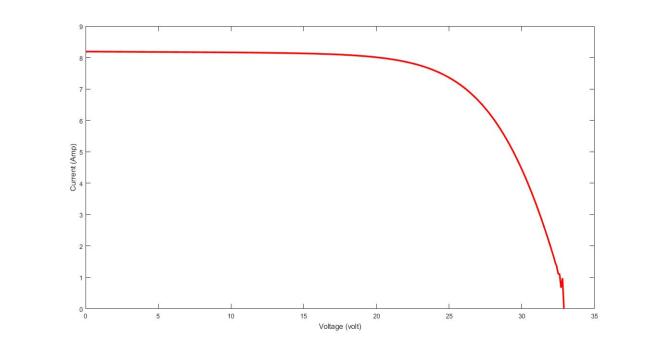
Themaximumpowerpointofasolarcellrepresentsthe utilization of a PV modules to its full extent. Here the coordinatesformaximumpowerpointcurrentandvoltage are[7.9A,26V].Atthisoperatingpointistrackingmaximum power or in other words it can be said that it is drawing maximumpowerfromPVPanel.Themaximumpowerpint voltagecandriftaccordinglywithwiderangeofparameters suchastemperaturedevicedegradationandsolarirradiance availabilityatlocation.
[1] Antony Anila and Menon Devika, “Islanding Detection Technique of Distribution Generation System” in 2016 International Conference on Circuit, Power and Computing Technologies [ICCPCT], 978-1-5090 1277-0/16/$31.00 ©2016 IEEE
[2] Rosin,H.Hõimoja,T.Möller,M.Lehtla”Residential Electricity Consumption and Loads Pattern Analysis”in978-1-4244-6981-9/10/$26.00©2010 IEEE.
[3]
"Ministry of New and Renewable Energy, Annual Report2015-2016"Retrieved2017-04-21.P.Rahi, Harish Kumar Thakur, and A. K. Chandel “Power
International Research Journal of Engineering and Technology (IRJET) e-ISSN: 2395-0056 Volume: 09 Issue: 08 | Aug 2022 www.irjet.net p-ISSN: 2395-0072
Sector Reforms in India: A Case Study” in 978-14244-1762-9/08/$25.00©02008IEEE.
[4] FarhaNaz,SarfarazShaikh,Dr.AliceCheeran“DSP Based Controller for various Power Electronics Converters Used in Micro-Grid “ in International JournalofRecentTrendsinEngineering&Research (IJRTER)Volume02,Issue10;October-2016[ISSN: 2455-1457]
[5] HemantPatel,ManjuGupta,AashishKumarBohre ,”MathematicalModelingandPerformanceAnalysis of MPPT based Solar PV System “ in 2016 International Conference on Electrical Power and Energy Systems (ICEPES) Maulana Azad National Institute of Technology, Bhopal, India. Dec 14-16, 2016.
[6] Vidhya K Viswambaran , Dr.Arfan Ghani and Dr. Erping Zhou “Modelling and Simulation of Maximum Power point Tracking Algorithms & ReviewofMPPTTechniquesforPVApplications”in 978-1-5090-5306-3/16/$31.00©2016IEEE.
[7] Ahmed M. Atallah, Almoataz Y. Abdelaziz, and RaihanS.Jumaah“ImplementationOfPerturbAnd Observe Mppt Of Pv System With Direct Control MethodUsingBuckAndBuckboostConverters”in Emerging Trends in Electrical, Electronics & Instrumentation Engineering: An international Journal(EEIEJ),Vol.1,No.1,February2014.
[8] Dr.RachanaGarg,Dr.AlkaSingh,ShikhaGupta“PV Cell Models and Dynamic Simulation of MPPT Trackers in MATLAB” in 2014 International Conference on Computing for Sustainable Global Development (INDIACom) ,978-93-80544-120/14/$31.00c 2014IEEE.
[9] William Christopher and Dr.R.Ramesh , “Comparative Study of P&O and InC MPPT Algorithms” American Journal of Engineering Research(AJER)e-ISSN:2320-0847p-ISSN:23200936Volume-02,Issue-12,pp-402-408.
[10] RobertL.Steigerwald,“PowerElectronicConverter Technology”,inProceedingsofTheIeee,Vol.89,No. 6, June 2001, Publisher Item Identifier S 00189219(01)04105-6.
[11] Jun Qi, Youbing Zhang*, Yi Chen “Modeling and maximumpowerpointtracking (MPPT) method for PV array under partial shade conditions “ in journalofCollegeoInformationEngineering,China. Available [online] Renewable Energy journal homepage:www.elsevier.com/locate/renene,2013 ElsevierLtd.
[12] N.Femia, G.Petrone, G. Spagnuolo, M. Vitelli, "OptimizingsamplingrateofP&OMPPTtechnique," inProceeding ofIEEE PESC, pp 1945- 1949,2004. "Ministry of New and Renewable Energy, Annual Report 2015-2016".Retrieved 2017-04-21 SPR305E-WHT-D by SunPower data sheet [online] Available:http://www.solarhub.com/solarhub_prod ucts/16980-SPR-305E-WHT-D-SunPower.
2022, IRJET | Impact Factor value: 7.529 | ISO 9001:2008 Certified Journal | Page1969