International Research Journal of Engineering and Technology (IRJET) e-ISSN: 2395-0056

Volume: 09 Issue: 08 | Aug 2022 www.irjet.net p-ISSN: 2395-0072
International Research Journal of Engineering and Technology (IRJET) e-ISSN: 2395-0056
Volume: 09 Issue: 08 | Aug 2022 www.irjet.net p-ISSN: 2395-0072
 Anjal Krishna T V1 , Krishna M M 2
1
Abstract – The steel industry is growing rapidlyinalmost all parts of the world. When global warming is a threat, use of steel structures is not only economical but also environmentally friendly. Here, the term "affordable"refers to time and cost. Being the most important aspect of time, steel structures are constructed in a very short time. In the seismic design of industrial buildings, the properties of horizontal ground motion are considered and upright ground movement is neglected. The main aim of the project is to compare the energy absorption as well as the energy transfer mechanismof different types of bracing systems such as K bracingandO grid bracing. Also, several materials are used in the analysis. The structure and shape of O Grid braces, can be used in any part of the structure without removing architectural space and architectural form. O bracing system has good ductility and stiffness. Thus, this O bracing can be effectively used in engineering structures in seismic prone areas which have the ability to withstand lateral loads.
Keywords: Forward, Bracing, energy absorption bracing
Amodularframeworkconsistsoflargerinterlockingsteels. Thissystemhasordoesnothaveverticalcomponents,and sincetheprimaryloadcomponentsaremembers,theyalso have lateral support. Ties are commonly used to steady buildingstructureagainstlateralloading.Mainfunctionof thestrutsistobecomestablethestructureandpreventits collapse. Various fastening systems are currently in use. Dependentontheshape,thebracesarediagonalbracings,Xshaped, K-shaped-shaped, elliptical and O-shaped. In this paper different types of bracing systems are numerically analysed.
***
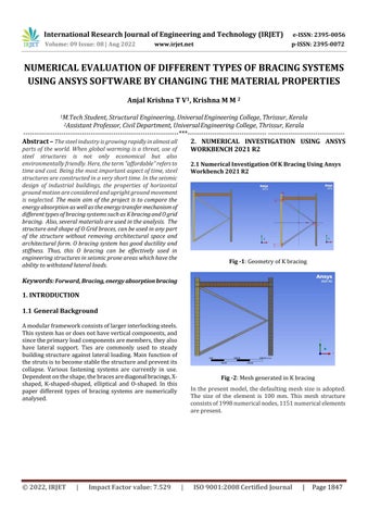
2.1
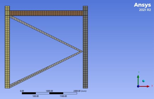
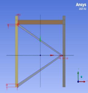
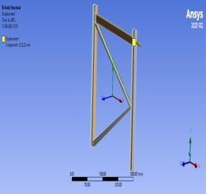
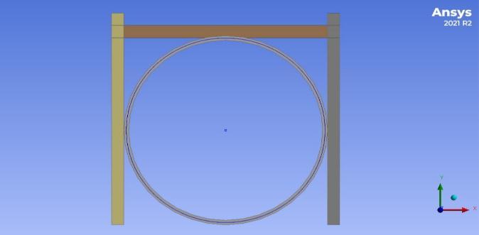
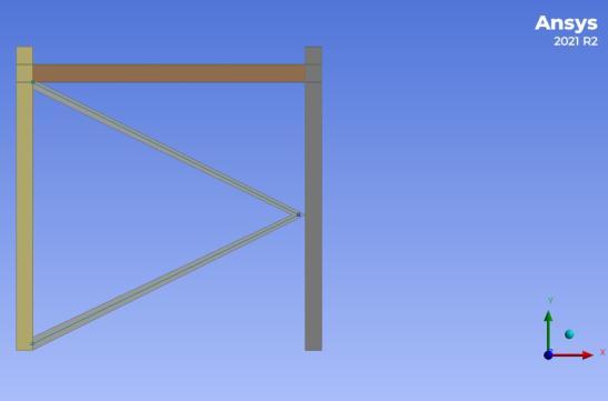
Fig -1:GeometryofKbracing
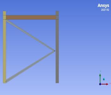
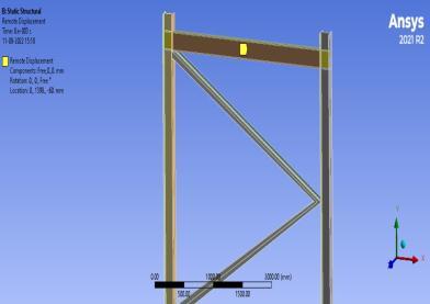
Fig -2
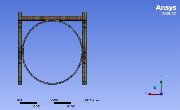
Inthe presentmodel,thedefaultingmeshsizeisadopted. The size of the element is 100 mm. This mesh structure consistsof1998numericalnodes,1151numericalelements arepresent.
International Research Journal of Engineering and Technology (IRJET) e-ISSN: 2395-0056
Volume: 09 Issue: 08 | Aug 2022 www.irjet.net p-ISSN: 2395-0072

Fig
Chart-3
Fig
International Research Journal of Engineering and Technology (IRJET) e-ISSN: 2395-0056
Volume: 09 Issue: 08 | Aug 2022 www.irjet.net p-ISSN: 2395-0072
[1]NewmarkNM,HallWJ.1973.“Seismicdesigncriteriafor nuclear reactor facilities”, Building Practices for Disaster Mitigation,NationalBureauofStandard,U.S.ReportNo.46.
[2]LaiSSP,BiggsJM.Inelasticresponsespectraforaseismic buildingdesign.JStructDiv1980;106:1295–310.
[3]MirandaE,BerteroVV.Evaluationofstrengthreduction factorsforearthquakeresistantdesign.EarthquakeSpectra 1994;10:357–79.
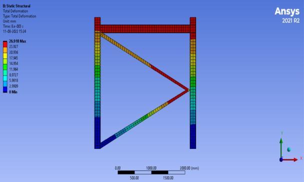
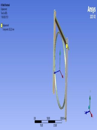
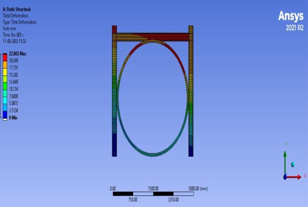
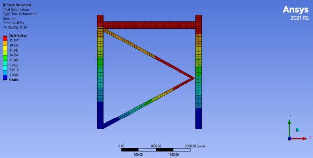
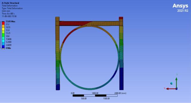
Fig -14:TotaldeformationsObracingusingdifferent materials
[4] Schafer BW, Ayhan D, Jeng J, Liu P, Padilla-Llano D, Peterman KD, et al. Seismic response and engineering of cold-formedsteelframedbuildings.Structures2016;8:197–212.
[5] FEMA P695, 2009. “Quantification of building seismic performancefactors”,Rep.FEMAP695,FederalEmergency ManagementAgency,Washington,D.C.
[6] Xian L, He Z, Ou X. Incorporation of collapse safety margin into direct earthquake loss estimate. Earthquakes Struct2016;10:429–50.
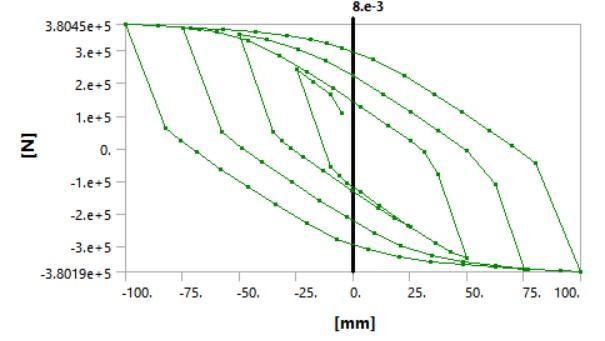
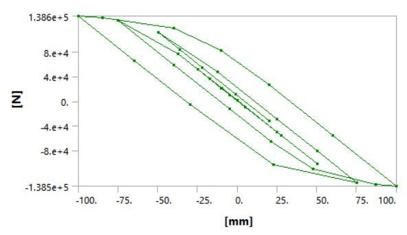
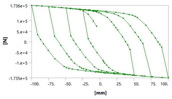
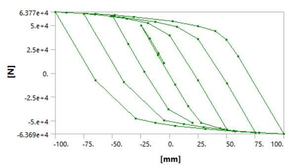
Chart-4:Load–displacementhysteresiscurvesofO Bracingusingdifferentmaterials
This study was mainly used to compare different types of bracingwithdifferentcrosssectiongeometries.Theforward andOsystems,and theyhaveadequateloadbearingsand can absorb great energy with their axial and flexural behavior.Unlikeotherbraces,thestructureandshapeofO Gridbraces,canbeusedinanypartofthestructurewithout removing architectural space and architectural form. O bracingsystemhasgoodductilityandstiffness.ThusthisO bracingcanbeeffectivelyusedinengineeringstructuresin seismic prone areas which have the ability to withstand lateralloads.
IwishtothanktheManagement,PrincipalandHeadofCivil EngineeringDepartmentofUniversalEngineeringCollege, Thrissur, affiliated by APJ Abdul Kalam Technological Universityfortheirsupport.Thispaperisbasedonthework carried out by me (Anjal Krishna T V), as part of my PG course, under the guidance of Krishna M M (Assistant professor,CivilDepartment,UniversalEngineeringCollege, Thrissur, Kerala). I express my gratitude towards her for valuableguidance.
[7] AlHamaydeh M, Abdullah S, Hamid A, Mustapha A. Seismic design factors for RC special moment-resisting frames in Dubai, UAE. Earthquake Eng Eng Vibr 2011;10:495–506.
[8] Zareian F, Krawinkler H. Structural system parameter selection based on collapse potential of buildings in earthquakes.JStructEng2010;136:933–43.
[9]HaseltonC,LielA,DeierleinG,DeanB,ChouJ.Seismic collapse safety of reinforced concrete buildings. I: Assessment of ductile moment frames. J Struct Eng 2011;137:481–91.
[10] Hsiao PC, Lehman DE, Roeder CW. Evaluation of the responsemodificationcoefficientandcollapsepotentialof specialconcentricallybracedframes.EarthquakeEngStruct Dyn2013;42:1547–64.
[11] Farahi M, Mofid M. On the quantification of seismic performance factors of Chevron Knee Bracings, in steel structures.EngStruct2013;46:155–64.
[12]ComeauG,VelchevK,RogersC.Developmentofseismic forcemodificationfactorsforcold-formedsteelstrapbraced walls.CanJCivEng2010;37:236–49.
[13] Leng J, Schafer B, Buonopane S. 2013. “Modeling the seismic response of coldformed steel framed buildings: Model development for the CFS-NEES building”, Annual StabilityConference,St.Louis,Missouri.
International Research Journal of Engineering and Technology (IRJET) e-ISSN: 2395-0056
Volume: 09 Issue: 08 | Aug 2022 www.irjet.net p-ISSN: 2395-0072
[14]LengJ,SchaferB,BuonopaneS.Seismiccomputational analysis of CFS-NEES building. Proceedings of 21th International Specialty Conference on Cold-Formed Steel Structures-Recent Research and Developments in ColdFormedSteelDesignandConstruction.2012.p.801–20.
[15]GusellaF,OrlandoM,SpinelliP.Pinchinginsteelrack joints:Numericalmodelling.IntJSteelStruct2019;19:131–46.
[16] AS/NZS4600, 2005. “Cold-formed steel structures”, AustralianBuildingCodesBoard.
[17]AISI.Standardforcold-formedsteelframing-Lateral design.Washington,D.C.:AmericanIronandSteelInstitute; 2007.
[18] Zeynalian M, Ronagh H, Hatami S. Seismic characteristicsofK-bracedcold-formedsteelshearwalls.J ConstrSteelRes2012;77:23–31.
[19]BuildingandHousingResearchCenter,2005.“Iranian codeofpracticefortheseismic-resistantdesignofbuildings, standardno.2800”,3rded.,Tehran,Iran.
[20]CanadianInstituteofSteelConstruction.Handbookof SteelConstruction.9thed.Toronto:Canada;2006.
2022, IRJET | Impact Factor value: 7.529 | ISO 9001:2008 Certified Journal