International Research Journal of Engineering and Technology (IRJET) e-ISSN: 2395-0056

Volume: 09 Issue: 08 | Aug 2022 www.irjet.net p-ISSN: 2395-0072
International Research Journal of Engineering and Technology (IRJET) e-ISSN: 2395-0056
Volume: 09 Issue: 08 | Aug 2022 www.irjet.net p-ISSN: 2395-0072
Dileep Kumar1, Dr. Priyanka Jaiswal2
1Master of Technology, Electronic and Communication Engineering, GITM, Lucknow, India 2Professor, Electronic and Communication Engineering, GITM, Lucknow, India ***
Abstract - The design suggestions for three antennas, each of which has a whole separate set of capabilities. The idea of fractal geometry is used by all three in the process of constructing small antennas that have superior performance than that of Microstrip Patch antennas (MPAs). Fractals are now one of the most fruitful areas of study in the world of antenna design. Their most notable advantage is their capacity to increase electrical length while basically maintaining the same amount of area anddeliveringimproved performance. The first idea is to create a hybrid fractal, which combines elements from two different kinds of fractals the Sierpinski Carpet and the Giuseppe Peanu andsuperimposes them on top of one other in order to provide the antenna the capability of narrow-band operation. Due to its ability to resonate in the S-band, it carries with it the potential to be used for WiMAX applications. The second idea is to use an iterative self-similar design to create a multi-band fractal, which is the second part of the second proposal. The antenna achieves its multi-band capabilities by cutting circles out of squares while preserving electrical conductivity throughout. The fact that it can resonate at five different frequencies within the range of three gigahertzto twelve gigahertzgives it a wide variety of potential uses, all of which are feasible within this frequency range. The third suggestionis to use anantenna with a very wide band, the manufacture of which has already been completed. The smallest of the three patches, this one was designed by cutting hexagonal holes out of a circular patch, and optimization was accomplished via the use of parametric analysis.
Key Words: Design,Analysis,Fractal,narrowband,multiband,ultrawideband,antenna.
Oneofthemostfundamentaljustificationsforthestatement is the revolution that has occurred in the sphere of communications.Wirelesscommunication[1]referstothe transmissionofdatabetweentwoormorelocationsthatare not connected by electrical conductors. This is one of the fastest growing segments in the above areas. It provides solutionstoavarietyofdifficultandunpleasantconditions, including: B. Cable laying in mountainous areas or long distances. Byusingamobilephone,youcansaveyourself thetroubleofcarryingawireddeviceathomeoratwork, andyoucannowcommunicateanytime,anywhere.WLAN (WirelessLocalAreaNetwork)innovationpermitsclientsto
interface with the Internet without the requirement for excessandcostlyrapidlinks,andisbroadlyperceivedasan adaptableandsavvyoptionincontrasttoconventionalfast informationtransmission.Oneofthecriticalmainimpetuses behindthishasbeentheconsistentcravingforpocketsized andopenspecializedgadgets,alsotheeffortlessnessofplan and assembling. Because of the developing interest for consistent coordination of cell organizations, for example, 3G,GSM,WPANandWLAN,itisbroadlyacceptedthatfuture remoteorganizationswillfundamentallyincorporateshortrangehighvelocityremoteadministrationsasafundamental component. Thefastdevelopmentofremoteinterchanges has prompted the inundation of new gadgets and frameworksintendedtosatisfythedevelopingneedforsight andsoundapplications.Littleuniversallyusefulradiowires need to endure the heap that addresses the issues of cell phonesandremoteorganizations,sotheyneedtohavehigh addition,widedatatransfercapacity,insertedestablishment, etc.
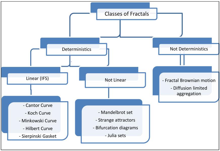
A fractal antenna is a device that employs a fractal, selfcomparativeplantoupgradetheedge(oninsidepartsorthe outsidestructure)ofmaterialthatcangetorcommunicate electromagnetic radiation inside a given all out surface region or volume. Staggered and space filling bends are differentnamesforfractalradiowires,howevertheessential componentistherepeatofatopicnorthofatleasttwoscale levels, or "cycles." thus, fractal receiving wires are minuscule,multibandorwideband,andhaveapplicationsin cell and microwave correspondences. The reaction of a fractalreceivingwireshiftsessentiallyfromthatofordinary receiving wire plans in that it might work with great tobrilliantexecutionatafewfrequenciessimultaneously.
International Research Journal of Engineering and Technology (IRJET) e-ISSN: 2395-0056
Volume: 09 Issue: 08 | Aug 2022 www.irjet.net p-ISSN: 2395-0072
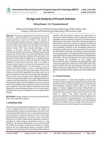
Figure-2.: Classes of fractals
.
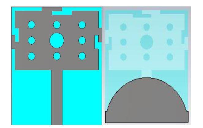
for example 12.5 mm, the proposed plan incorporates a sticking the component square shape is introduced to Giuseppe Peanu Fractal Slits, subsequently framing the premise of the round Sierpinski opening course of action. Thesubstrateismadeoflow-costfibreglassthatis1.6mm thickandcoatedwith.Arectangularpieceof3mmX25mm servesastheground.
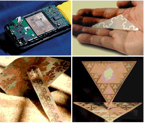
Figure-3: front and backside view.
Table-1.: Design Parameter Dimension.
Serial Number Parameter Value 1
Lengthofsubstrate 30mm 2 Lengthofpatch(front) 16mm 3 Lengthofpatch(back) 3mm 4 Centreofcircle(back) (0,-16) 5 Radiusofbiggercircle 2mm 6 Widthofsubstrate 25mm 7 Lengthofnotchonpatch W/3orL/3 8 Widthofnotch 1mm 9 Center of first circle (front) (0,6.5) 10 Radiusofsmallercircle 1mm
International Research Journal of Engineering and Technology (IRJET) e-ISSN: 2395-0056
Volume: 09 Issue: 08 | Aug 2022 www.irjet.net p-ISSN: 2395-0072
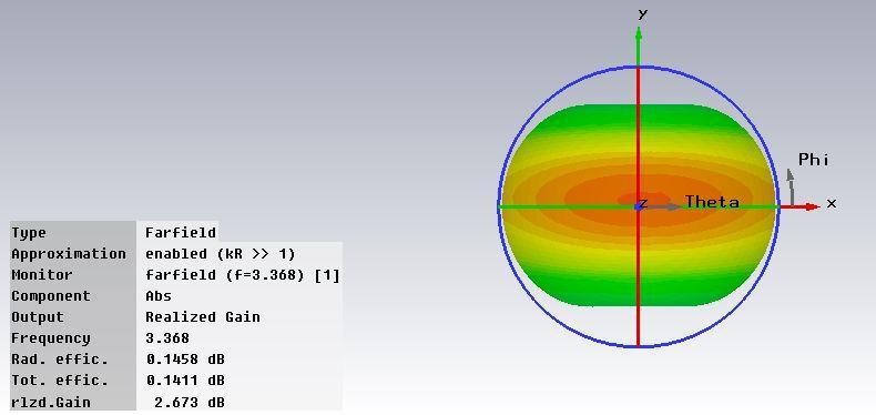
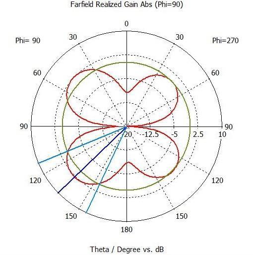
Figure-4: Gain of Realized.
Figure-6: C.P.W-Fed Fractal.
Table-2: Dimension of the Circle and Square.
Iteration no Length of edge of square. Internal radius.
1.0 50mm 24.5mm 2.0 36mm 17.5mm 3.0 25mm 12mm 4.0 17.6mm 8.4mm
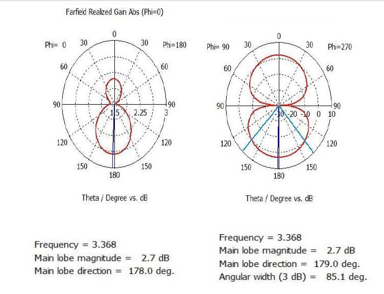
Figure-5: Patterns of Radiation.
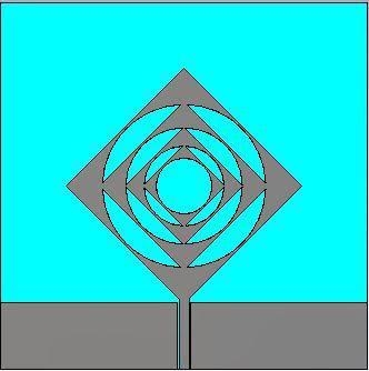
Theantennaismadebycontinuallyanditerativelycutting circlesfromsquareswiththedimensionsgiveninthetable below.ThepatchsarefedusingtheCo-PlanarWaveguidefeedingapproach,whichisdetailedinthetableabove.But first,here'showtheantennaisdesigned.
Table-3: Details Size Parameter of the design
S.no Parameter Value
1 Width=lengthofsubstrate. 110.0mm 2 Thicknessofsubstrate. 1.530mm 3 SpacingbetweenFEEDand AdjacentGround. 0.50mm 4 FeedLength. 24.50mm 5 FeedWidth. 3.0mm
6 LengthoftheC.P.Wground. 24.50mm
International Research Journal of Engineering and Technology (IRJET) e-ISSN: 2395-0056
Volume: 09 Issue: 08 | Aug 2022 www.irjet.net p-ISSN: 2395-0072
Figure-7: Gain of Realized (3D), When Fc= 3.52GHz.
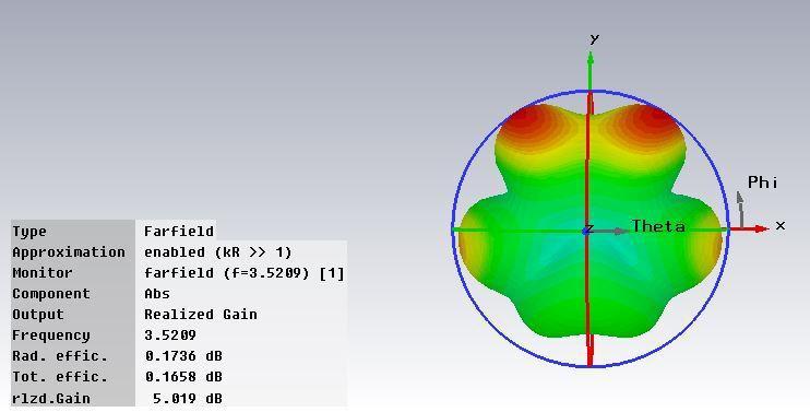
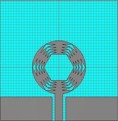
Figure-9: Proposed Design For Antenna. Table-4: Design Parameter.
Serial Number Radius of Outer Circle (in mm).
Length of sides of regular hexagon the regular
1.0 10.0 millimeter. 09.950millimeter.
2.0 8.7060 millimeter. 08.6560millimeter.
3.0 7.5740 millimeter. 07.5240millimeter.
4.0 6.5830 millimeter. 06.5330millimeter.
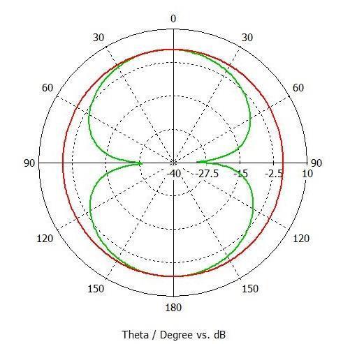
Figure-8: Patterns of Radiation.
Thisoperationisrepeatedfivetimes,ensuringthatelectrical communicationismaintainedatalltimes.ACPWfeedwith thedimensionslistedintable5.2isattached.Thesubstrate isFR4,whichhasadi-electricstableof4.4.Itsmeasurements areinadditionshowninthetableabove.
5.0 5.7170 millimeter. 05.6670millimeter.
Table-5: Dimension Parameter for Antenna
Parameter Length Width
Feed-line. 11.50millimeter. 03.0millimeter. Substrate. 45.0millimeter. 44.0millimeter. Ground Patch. 9.0millimeter. 19.50millimeter.
International Research Journal of Engineering and Technology (IRJET) e-ISSN: 2395-0056
Volume: 09 Issue: 08 | Aug 2022 www.irjet.net p-ISSN: 2395-0072
narrowbandantennawitharesonancefrequencyof3.386 GHz.
It may be manufactured to use the attributes of the individual bands since resonant frequencies exist at numerous points over the SHF. It was a CPW-fed fractal created by iteratively carving out circles inside squares while maintaining electrical connection, on a dielectric substrateFR4withadielectricconstantof4.4andnoground plane.Theresultingantennaradiatedatseveralfrequencies intheSHFrange(3.52GHz,5.7GHz,8GHz,9.95GHz,and12 GHz),makingitmulti-bandcapable.
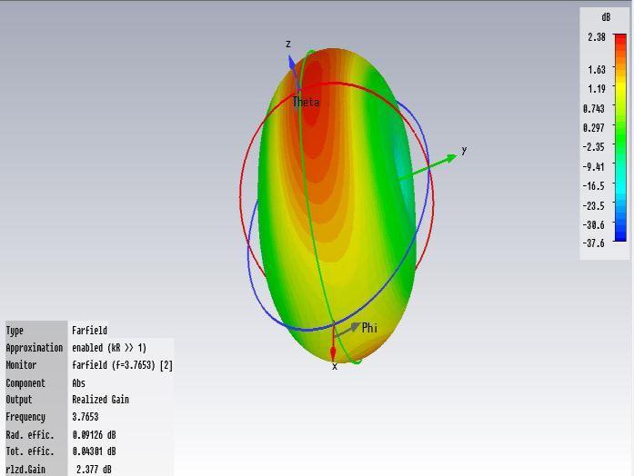
Figure-10: Patterns of Radiation, At fc= 3.7653 Gigahertz.
An unique Ultra Wide-Band Application design that used hexagonalholescutwithinacircularpatchrepeatedlyovera FR4 substrate. It was CPW-fed, and the slot gap was optimisedusingparametricanalysis.Theantennawasalso made from scratch. However, due to a lack of advanced equipment,measurementscouldnotbecarriedout.
1.http://en.wikipedia.org/wiki/Antenna_(radio)
2. K. Fujimoto and J. James, Mobile Antenna Systems Handbook.ArtechHouse,1994
3.W.Beynon,“Marconi,RadiowavesandtheIonosphere,” RadioScience,vol.vol.10,no.7,pp.657–664,July,1975.
4.Choukiker,YogeshKumar(2013)“Investigations on some compact wideband fractal antennas”PhDthesis
5. Agrawal, Sonu (2013) Design and Analysis of Hexagonal Shaped Fractal Antennas.MTechthesis
6.ZhiNingChenandMichaelY.W.Chia,“BroadbandPlanar Antennas,DesignandApplications,”JohnWiley&Sons,Ltd.
Figure-11: Realized-Gain (3-D).
The goal in writing this thesis was to better comprehend andcontributetotheprocessofcombiningantennatheory withfractalgeometry.ItexplainshowtocreateMicrostrip and Fractal antennas, as well as the theory behind them. Threedesignshavebeenproposed:anarrow-band,amultiband, and an ultra-wide band, the last of which has been manufactured.Theradiationandgainpatternsofeachhave beenextensivelyexamined.Inaddition,theeffectivenessof introducingfractalintoantennatheoryhasbeenhighlighted.
ThestudyofaFractalhybridthatdemonstratednarrowband behaviour.ThedesignbeganwithaGiuseppePeanufractal, whichservedasthefoundationforanotherfractalgeometry, Sierpinskigeometry.Thisantenna'sBandwidthPercentage wasdeterminedtobe40.421percent,indicatingthatitisa
7.K.L.Wong,PlanarAntennasforWirelessCommunications. Wiley-Interscience,2000
8. A. F. Peterson, S. L. Ray, and R. Mittra, Computational Methods for Electromagnetics. IEEE Press Series on ElectromagneticWaveTheory,1997.
9. E. K. Miller, L. Medgyesi Mitschang, and E. H. Newman, Computational Electromagnetics: Frequency-Domain MethodofMoments.IEEEPress,1992
10. W. C. Chew, J. Jin, E. Michielssen, and J. Song, Fast and Efficient Algorithms in Computational Electromagnetics. ArtechHouse,2001
11.IE3DUserManual.ZelandSofwareInc,2003.
12.FEKOUser‟sManual,Suite5.1.EMSoftware&Systems, SouthAfrica
International Research Journal of Engineering and Technology (IRJET) e-ISSN: 2395-0056 Volume: 09 Issue: 08 | Aug 2022 www.irjet.net p-ISSN: 2395-0072
13.UserManualfortheCST.IMSTGmbH,Germany,2004.
14.UserManualforHFSS.AnsoftCorporationPittsburg,PA, USA.,2000
15. J. Robinson and Y. Rahmat-Samii, “Particle Swarm Optimization In Electromagnetics,” IEEE Transactions on AntennasandPropagation,vol.52,no.2,pp.397–407,2004.
16. C. G. Christodoulou, M. Georgioipoulos, and A. H. E. Zooghby, Applications of Neural Networks in Smart Antennas for Mobile Communications. Applied ComputationalIntelligence,CRCPress,LLC,2000.
17.C.Christodoulou,M.Georgiopoulos,andC.Christopoulos, ApplicationsofNeural
NetworksinElectromagnetics.ArtechHouse,2001.
18. Y. Rahmat-Samii and E. Michielssen, Electromagnetic OptimizationbyGeneticAlgorithms.NewYork:JohnWiley& Sons,1999.
19.D.S.Linden,AutomatedDesignandOptimizationofWire Antennas Using Genetic Algorithms. PhD thesis, Massachusetts Institute of Technology, Department of ElectricalEngineeringandComputerScience,1997.
20.D.T.Pham,A.Ghanbarzadeh,E.Ko¸c,S.Otri,S.Rahim, andM.Zaidi,“TheBeesAlgorithm:ANovelToolforComplex Optimisation Problems,” in Proc. 2nd Int. Virtual Conf. on Intelligent Production Machines and Systems (IPROMS 2006),2006
21. E. K. P. Chong and S. H. Zak, An Introduction to Optimization. Wiley-Interscience Series in Discrete MathematicsandOptimization,2001.
22.C.Puente,J.Romeu,R.Bartoleme,andR.Pous,“Fractal multiband antenna based on Sierpinski gasket,” Electron. Lett.,vol.32,pp.1-2,1996.
23.C.Puente-Baliarda,J.Romeu,R.Pous,andA.Cardama, “On the behavior of the Sierpinski multiband fractal antenna,” IEEE Trans. Ant. Propagat., vol. 46, pp. 517524,1998.
24. N. Cohen, “Fractal antenna applications in wireless telecommunications,” in Professional Program Proc. of ElectronicsIndustriesForumofNewEngland,1997,IEEE, pp.43-49,1997.
25. C. Puente-Baliarda, J. Romeu, R. Pous, J. Ramis, and A. Hijazo, “Small but long Koch fractal monopole,” Electron. Lett.,vol.34,pp.9-10,1998.
26.E.E.C.deOliveira,P.H.daF.Silva,A.L.P.S.Campos,S. Gonc, A.D.Silva, “Overall Size Antenna Reduction using
Fractal Geometry”, Microwave and Optical Technology Letters,vol.51,no.3,March2009,pp.671-674.
27. B. B. Mandlebrot, The Fractal Geometry of Nature. W.H.FreemanandCompany,1983.