International Research Journal of Engineering and Technology (IRJET) e-ISSN:2395-0056

Volume: 09 Issue: 08 | Aug 2022 www.irjet.net p-ISSN:2395-0072
International Research Journal of Engineering and Technology (IRJET) e-ISSN:2395-0056
Volume: 09 Issue: 08 | Aug 2022 www.irjet.net p-ISSN:2395-0072
Sudhanshu Maurya1, Vineet Gupta2, Mukesh yadav3
.
1UG-scholar, department of mechanical engineering, JSS Academy of Technical Education, Noida, India
2UG-scholar, department of mechanical engineering, JSS Academy of Technical Education, Noida, India 3Assistant professor department of mechanical engineering, JSS Academy of Technical Education, Noida, India ***
Abstract - When it comes to a student designcompetition for ATVs, Baja SAE India has always been a pioneer. Their racing events on various tracks for various events (such as braking, acceleration, and endurance) necessitates varied performance parameters, which must be met by the powertrain system in order to achieve greater vehicle performance. Things have altered with their most recent rules modifications, and the significance of a better and efficient engine system has grown.
They have incorporated the 4-WD option in their most recent rulebook version. The purpose of this study is to discuss how to develop and optimize the 4-WD powertrain system for mBAJA. The event is powered by a Briggs and Stratton engine, which is requiredof all teams
Key Words: Single stage 4WD reduction gearbox, BAJA SAE INDIA, All-terrain vehicle (ATV), differential, gear design, simulation, CAD, FEM
Baja SAE Indian is a student design competition that compels the students to design and fabricate their own ATVwhichmustcomplywiththerulebook.Thedesigning processstartstogetherinfivedifferentdepartmentsbutin this paper, we will focus entirely on powertrain system designing and its optimization. Engine specifications are givenintable Ⅰ
From various events of this competition, three of them challengethepowertrainsystemthemost.
● Accelerationtest(itrequiresveryhigh-power transmissionatveryhightorque)
● Brakestest(thisinvolvespanicbraking)
● Endurancerace(thisisthemostdemandingpart oftheeventandrequirescontinuousaccelerationand braking).
Our gear train system consists of a 2-stage reduction gearbox, paired with Gazed GX9 CVT. The propeller shaft goes from idler gear to the front differential for transferringthepowertothefrontwheels.
For the front, we decided to go with the locking differential as compared to the rear, where we decided onlytohaveasolidshaft.
This is so because not having a differential, especially the locking one will affect the steering performance and increase the overall turning radius of the vehicle. The locking differential which we will be using is the Torsion differential.
After looking into the various materials available for the easy fabrication of gears and considering our loading conditions.Ithas beendecidedAISI4340 willbegood for reductiongearsanddifferentialalso.
AISI4340 has excellent fatiguestrength and can maintain its properties even at high temperature conditions along withgoodwearstrength.
Material’s mechanical properties are given below in table Ⅱ
International Research Journal of Engineering and Technology (IRJET) e-ISSN:2395-0056
Volume: 09 Issue: 08 | Aug 2022 www.irjet.net p-ISSN:2395-0072
Serial. no Mechanical properties of AISI 4340
Mechanical properties Values
1 TensileStrength,Ultimate 1110MPa
2 TensileStrength,yield 720MPa
3 Modulusofelasticity 205GPa
4 Bulkmodulus 140GPa
5 Poisson’sratio 0.29
6 Shearmodulus 80GPa
There is a stringent restriction on parameters that you cannot exceed, like braking distance, minimum acceleration,turningradiusandtopspeed.
Two of which, top speed and minimum acceleration influencethedesignofthegeartrainsystem.
First, we calculated the maximum tyre force which is required to meet all the boundary constraints like acceleration and top speed within a given amount of engine power. That is the design of the gear system is optimizedanddoesnotgounderanyfailureasouraimto design the unit which provides the output velocity @60kmph and able to climb 35-degree slope to provide bothhighspeedandtorque
Therestofthedesignprocedureisinthefollowingways: CalculationofGearRatios→DesignofGears→Calculation ofLoadsactingonthegears→GearMaterialsSelection→ simulations of gears (under various extreme loading conditions) → Calculation of factors depends upon the gears.
vehicle
7 CVTratio[max,min] [3.9,0.9]
8 Efficiency of the transmission(ηt) 90%
9 Rollingresistance(µ) 0.15
Anticipatingtheworst-case scenarios,thevalueofRolling Resistanceistakenas0.15andefficiencyistakenas90%. these values are validated by various other research paper.
A.2-stagereductionGearcalculation
Calculationofgearratios considering the technical specification as per requirements
1. rollingresistance(Fr)= µ×M×gcos35=301N
2. graderesistance(Fg)=M×g×sin35 =1405.26N
3. dragresistance(Fd)=⍴×A×Cd ×V2 =65N whereCd=0.4, ⍴=1.225kg/m3,A=1.5m2,V=60km/h thus,totalresistance(R)=Fr+Fg+Fd Tractiveforce≥ totalResistance (19.66×.085×3.9×GR)/(rdynamic) ≥1803.76 (19.66×.90×3.9×GR)/(.2682) ≥1803.76 GR≥7.0072
considering the gradability and top speed final GR is chosentobethevalueof7.11 since the gear train system is designed for 2 stage reduction.so,reductionateachstagewillbe=(7,11)1/2 so,thereductionateachstageis=2.66
Calculation of minimum number of teeth, module, FOS, facewidthfor1ststagereduction
b=Sut/3=585.33N/mm2 b×Yp < b×Yg(prioritizingpinionsinceit’stheweakest)
Zp:14(seereference[3])
International Research Journal of Engineering and Technology (IRJET) e-ISSN:2395-0056
Volume: 09 Issue: 08 | Aug 2022 www.irjet.net p-ISSN:2395-0072
Zg=14×2.66=38
Dp =14M
Dg =38M (whereMismodule)
MT :torqueonthePinion
MT =(60×1000000×PE×ηT )/[2×π×(3800/3.9)]N-mm
MT =66178.39N-mm
CS = 1.5 (value taken from data handbook of VB.BHANDARI)
CV ={6/(6+V)}
Vp ={(π×DP×N)/(60×1000)}m/s
VP=(π×14M×974)/60000m/s
VP=0.714M m/s
Cv=(6/(6+.714M))
PT =(2MT)/DP N
PT =(2×66178.39)/14M N
LetFacewidth(WF)=8M
Fb =M×F×b×Yp
Fb =M×8M×585.33×0.279
Fb = 1306.456 M^2 N
Fw=Dp ×F×Q×K
LetFwidth=8M mm
Q=[(2×Zg)/(Zg+Zp)]=[(2×38)/(38+14)]=1.4615
K=0.16×(BHN/100)^2
K=3.8416
Fw =14M×8M×1.4615×3.8416=628.82M^2
As Fw < Fb(So We have to Design the gear against wear load)
Peff =(Cs/Cv)×Pt
Peff =[1.5/{6/(6+.714M)}]×{(2×66178.39)/14M}]
Fw =FOSwear×Peff
628.8M^2=1.25×[1.5/{6/(6+.714M)}]×{(2×66178.39)/14} ]
(assuming FOSwear=1.25, since it will be enough for wear load.)
0.213×M3-0.714×M-6=0 M=3.40
ForCheckingthebeamStress
Fb =Peff *FOSbending
1306.456* 3.42 =6050*FOSbending
FOSbending =15998.5/6050
FOSbending =2.49(forFOSwear=1.25)
Module(M)=3.4
Zp=14,Zg=38
Dp=14*3.5=45.5mm Dg =38*3.5=123.5mm WF =8*3.5=28mm
TABLE Ⅳ.1STT STAGEREDUCTIONCALCULATIONRESULT
Serial. no 1st stage reduction result Specification value 1 Piniondiameter(Dp) 45.5mm
Idlerdiameter(Dg) 123.5mm
Facewidth(WF) 28mm 4 Number of teeths of pinion(Zp) 14 5 Number of teeths of idler gear(Zg) 38 6 Module(M) 3.4 7 FOSbending 2.49 8 FOSwear 1.25
Calculation of minimum number of teeth, module, FOS, face width for 2nd stage reduction by performing the similar calculation methodology for 1st stage reduction, thesecondstagereductioncalculationisshownintable Ⅴ
© 2022, IRJET | Impact Factor value: 7.529 | ISO 9001:2008 Certified Journal | Page1626
International Research Journal of Engineering and Technology (IRJET) e-ISSN:2395-0056
Volume: 09 Issue: 08 | Aug 2022 www.irjet.net p-ISSN:2395-0072
TABLE Ⅴ 2NDSTAGEREDUCTIONCALCULATIONRESULT
Serial . no 2nd stage reduction result
Specification value
1 Piniondiameter(Dp) 59.5mm
2 Idlerdiameter(Dg) 172.25mm
3 Facewidth(WF) 34mm
4 Number of teeths of pinion(Zp) 15 5 Number of teeths of idlergear(Zg) 41 6 Module(M) 4.25
7 FOSbending 1.83 8 FOSwear 1.25
Torsion differential consists of various gears like spur gear,wormgearandwormwheel,allthreeworkstogether toprovidethetractioninalltype’sroadconditions.
Specification values of all these gears are calculated by using the same calculation methodology as used in calculationofspecificationofgearsat1ststagereduction.
Design of the spur gear is finalized by using the same methodology as used for the calculation of the 1st stage reduction,andthedesignspecificationvaluesaregivenin table Ⅵ
TABLEⅥ .SPURGEARDESIGNCALCULATIONRESULT
11 Rootdiameter(dr) 35mm
12 Circularpitch(Pc) 6.28mm 13 Diametralpitch(Pa) 0.5mm 14 Tooththickness(Th) 3.14mm 15 Filletradius(r) 0.8mm 16 Workingdepth(WD) 4mm
Design specifications of the worm gear are given in table Ⅶ andoffwormwheelaregivenintable Ⅷ
TABLE Ⅶ.WORMGEARDESIGNCALCULATIONRESULT
Serial . no Design specification of worm gear Specification value
1 Module(M) 2
2 Pressureangle(��) 20° 3 Numberofteeth(z) 20 4 Pitch circle diameter (d) 40mm 5 Addendum(ha) 2.39mm 6 Leadangle 45mm 7 Facewidth 30mm 8 Helixangle 45mm A.
Table Ⅷ WORMWHEELDESIGNCALCULATIONRESULT
Serial . no Design specification of worm gear Specification value
1 Module(M) 2
Specification value
Serial . no spur gear design calculation
1 Module(M) 2
2 Pressureangle(��) 20° 3 Numberofteeth(z) 20
4 Centerdistance(a) 40mm 5 Pitch circle diameter (d) 40mm
6 Basediameter(db) 35mm
7 Addendum(ha) 2mm
8 Dedendum(hb) 2.5mm 9 Toothdepth(h) 4.5mm 10 Tipdiameter(da) 44mm
2 Pressureangle(��) 20° 3 Numberofteeth(z) 10 4 Pitch circle diameter (d) 20mm
5 Addendum(ha) 2.39mm 6 Leadangle 45mm 7 Facewidth 55mm 8 Helixangle 45mm
Software’susedforCADandFEMareSolidWorks2020 andANSYS2019
International Research Journal of Engineering and Technology (IRJET) e-ISSN:2395-0056
Volume: 09 Issue: 08 | Aug 2022 www.irjet.net p-ISSN:2395-0072
● CAD and FEA of 2-stage reduction gear
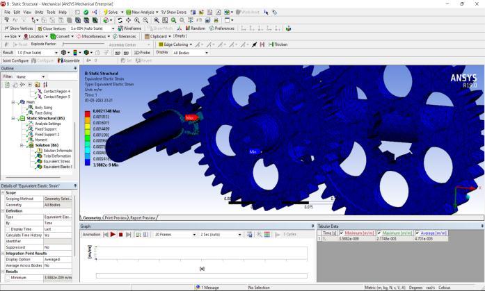
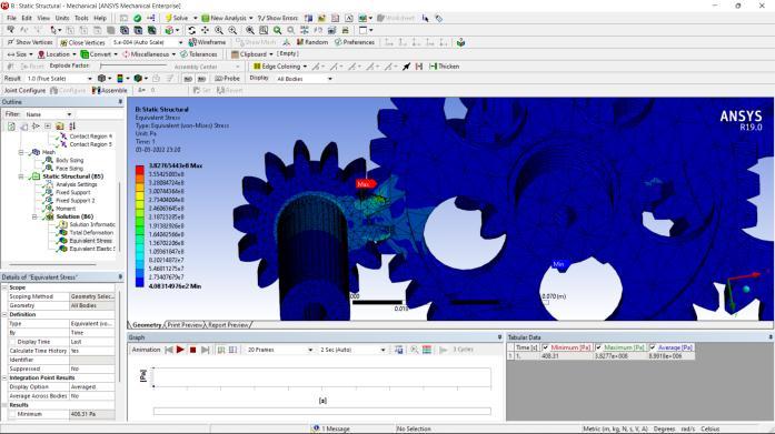
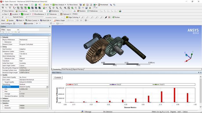
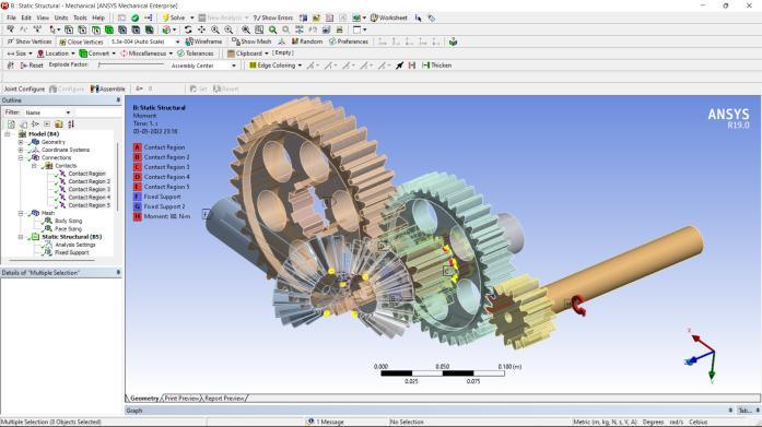
Figure1;CADmodelof2-stagereduction4WDgear system
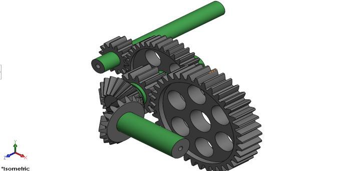
Figure4
Figure3and4;showingnumberofelementsandelement qualityandskewnessoftetrahedral,hexahedraland wed15elements
Figure2;contactregionandboundaryconditionsapplied forthesimulationof2stage4WDgearreductionsystem
Figure5;showingthemaximumandminimumequivalent von-misesstressonthegear-trainsystem
Figure3
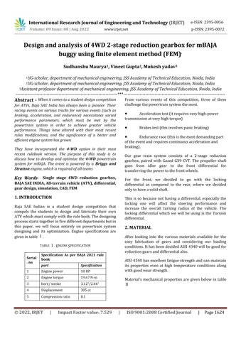
Figure6;showingthemaximumandminimumequivalent elasticstrainongear-trainsystem
International Research Journal of Engineering and Technology (IRJET) e-ISSN:2395-0056
Volume: 09 Issue: 08 | Aug 2022 www.irjet.net p-ISSN:2395-0072
Figure7;showingthemaximumandminimumtotal deformationwhenenginetorqueisapplied physics preference mechanical element size and type 7.5e-003 m (tetrahedral, hexahedral, and Wed15 ) number of nodes 196684 number of elements 119343
Table Ⅸ showingthenumberofelements,elementsize andtypeofelementsusedduringthesimulation value maximum minimum equivalent vonmises stress 3.8277e+008 [Pa] 408.31 [Pa] total deformation 2.022e-004 [m] 0 [m] equivalent strain 2.1748e-003 3.5882e-009
Table Ⅹ showingthesimulationresultof2stage4-WD reductiongeartrainsystem.
● CAD and FEA for torsen differential
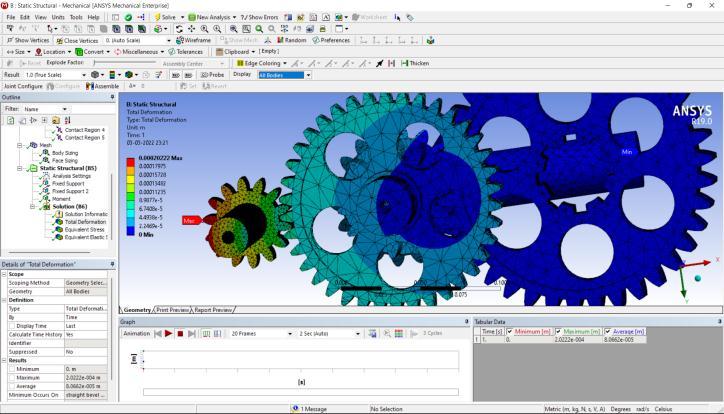
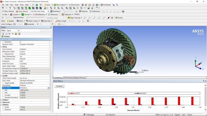
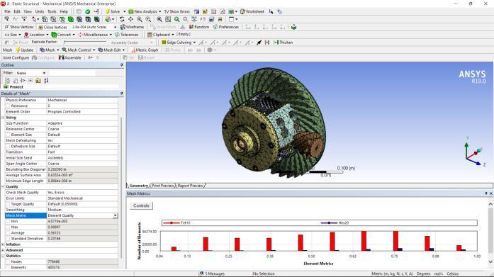
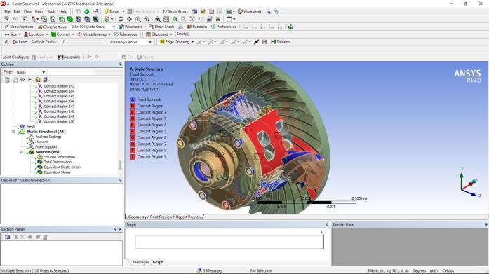
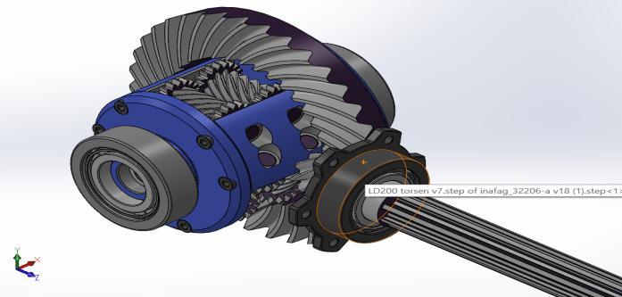
Figure9;showingthecontactregionsbetweenthe differentpartsoftorsendifferential.
Figure10;
Figure8CADmodeloftorsiondifferential.
Figure11. (figure10and11;showingnumberofelementsand elementqualityandskewnessoftetrahedral,and hexahedralelements)
International Research Journal of Engineering and Technology (IRJET) e-ISSN:2395-0056
Volume: 09 Issue: 08 | Aug 2022 www.irjet.net p-ISSN:2395-0072
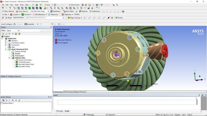
Figure12;showingtheboundaryconditionappliedduring thetimeofsimulation.
Figure15;showingthemaximumandminimum deformationproducedduringthetimeofloading.
physics preference mechanical element size and type program controlled (*due to low processing power) number of nodes 778466 number of elements 403215
Figure13;showingthemaximumandminimumvonmisesstressdevelopedduringthetimeofsimulation.
Table Ⅺ showingthenumberofelements,elementsize andtypeofelementsusedduringthesimulation value maximum minimum equivalent vonmises stress 7.4531e+008 [Pa] 535.06 [Pa] total deformation 3.9722e-005 [m] 0 [m] equivalent strain 3.8334e-003 6.3027e-009
Table Ⅻ showingthesimulationresultof2stage4-WD reductiongeartrainsystem.
TABLE ⅫⅠ SIMULATION RESULT SHOWING THE COMPARISON BETWEEN HAND CALCULATION AND FEA RESULT
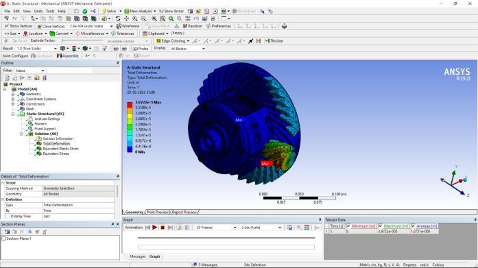
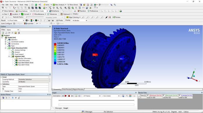
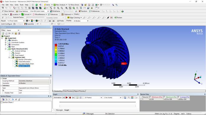
Figure14;showingthemaximumandminimumelastic straindevelopedduringsimulationasperourloading condition
International Research Journal of Engineering and Technology (IRJET) e-ISSN:2395-0056
Volume: 09 Issue: 08 | Aug 2022 www.irjet.net p-ISSN:2395-0072
The gearbox has been meticulously developed using the most up-to-date calculations and analyses. The ultimate gear ratio is 7.11, with the first stage at 2.66 and the second stage at 2.66. AISI 4340 is the material chosen for the designing of the gears. All of the gear analysis was completed and the results were reported. The gearbox is employedinavarietyofapplications.
All parts that can endure harsh circumstances in an ATV for about 2 years with regular maintenance and the calculation for gear ratio, minimum number of teeth, bearingforcesforadvancedhelicalgears,andanalysis.Are done on all the parts to withstand all the extreme conditionforeventslikeBAJASAE
[1] BajaSAEIndia2021rulebook
[2] TheoryofmachinesbyR.S.Khurmi
[3] V. B Bhandari, Design of Machine Elements, McGrawHillEducation.
[4] Yong Huh “A study on the differential gearing device withlimitedslipdifferential”on11October2009.
[5] Ishan Bajpai “Comparative Study of Torsion Differential” International Journal of research In Mechanical engineering & technology Vol. 5, Issue 1, November2014-April2011.
[6] Yong Huh, Hyung-Ick Kim “A study on the differential gearing device with the faculty of a limited slip differential”InternationalJournalofPrecisionEngineering andManufacturing”July2009.
[7] ShivanaMahes, Uber Mantovani Alessandro Tasca “TORSEN DIFFERENTIAL FOR FSAE 2016” international journalMarch2016
[8] AnsysMechanicalmanual2019
[9] Golabi, Sa'id, Javad Jafari Fesharaki, and Maryam Yazdipoor. "Gear train optimization based on minimum volume/weight design." Mechanism and machine theory 73(2014):197-217.