International Research Journal of Engineering and Technology (IRJET) e-ISSN: 2395-0056

Volume: 09 Issue: 08 | Aug 2022 www.irjet.net p-ISSN: 2395-0072
International Research Journal of Engineering and Technology (IRJET) e-ISSN: 2395-0056
Volume: 09 Issue: 08 | Aug 2022 www.irjet.net p-ISSN: 2395-0072
Abstract - This paper describes autonomous navigation and its implementation for a non-holonomic autonomous delivery robot using the Robot Operating System (ROS), as well as the robot's full design, implementation, and dynamic modelling. Delivery Based on the rocker and bogie mechanism, the Rocker - Bogie robot aimed to deliver anything from one location to another. The requirement for the development of a highly stable suspension system capable of operating on a variety of terrain surfaces while keeping all wheels in contact with the ground. Adaptive Monte Carlo Localization (AMCL) is used for robot localization, which uses a particle filter to track a robot's pose against a known map. It also makes use of mapping, which is based on the Gmapping package. It is used for laser-based SLAM (Simultaneous Localization and Mapping) mapping. A 2-D occupancy grid map is created using LIDAR. The Dijkstra algorithm is used to plan a path to a goal position using a persistent map created by the robot during the mapping process.
Mobilerobotshavebeenwidelyusedinavarietyoftasks, includingmilitaryandindustrialapplications,overthelast decade.[1–4],planetaryexploration[5–8],rescueoperations [9,10]aswellashome/medicalservices[11,12].Asaresult, it is not surprising that high mobility in a variety of environments has been a primary factor in evaluating the performance of the mobile robot [13]. Mobile robots are classified into three types based on the locomotive mechanismusedtoachievethedesiredmobility:leg-type, track-type,andwheel-typemobilerobots.Whiletheleg-type mobilerobothasthebestadaptabilitytoallenvironments, itsmechanismisquitecomplicatedbecauseactivecontrol algorithms with additional actuators and sensors are requiredtomaintainitsbalance,whichinevitablyresultsin slowmovementandpoorenergyefficiency[14,15].Because ofitsinherentstability,thetrack-typemobilerobotprovides acceptable mobility in an off-road environment, but excessive friction loss during direction change results in poor energy efficiency. [16]. The wheel-type mobile robotisconstructedinthesimplestconfigurationcompared tootheralternatives,,fast movementisguaranteedwithout
anycomplicatedcontrolstrategy.However,itsadaptability toanenvironmentdoesnotseemtobesufficientlygoodand itsmobilityisrestricteddependingonboththetypeandthe size of encountered obstacle [15,17]. The rocker-bogie designeliminatestheneedforspringsorstubaxlesineach wheel,allowingtherovertoclimboverobstaclestwicethe diameter of the wheel while retaining the rover's manoeuvrabilitallsixwheelsontheground.Thetiltstability of any suspension system is limited by the height of the centerofgravity.Astheweightedsidegives,systemswith springs tend to tilt more easily. The curiosity rover of the MarsScienceLaboratorymissioncanendureatiltofatleast 45degreesineitherdirectionwithoutoverturningbasedon itscenterofgravity,automatedsensorspreventtherover fromtiltingmorethan30degrees [18].Theterm“rocker” describestherockingaspectofthelargerlinkspresenton eachsideofthesuspension systemandthebalanceofthe bogieastheserockersareconnectedandthevehiclechassis throughamodifieddifferential.Inthesystem,“bogie”refers totheconjoininglinksthathaveadrivewheelattachedat eachend.Bogieswerecommonlyusedtoloadingastracksof armytanksasidlersdistributingtheloadovertheterrain. Bogies were also quite commonly used on the trailers of semitrailertrucksasthatverytimethetruckswillhaveto carryamuchheavierload[19].Thisrobotservesandassists societybecauseitincorporatesmanyengineeringfieldssuch as mechanics, electricity, electronics, and design. It also serves hospitals and other public buildings. This thesis delvesintotheentireprocessofimplementingtheproposed prototype,includingliteraturereviewsonsimilarprevious robotsandcontrolmethodologies.Themechanicalsectionof the robot design is then reviewed, which discusses the design and calculations for assembling the rocker-bogie. Thenwegotothecontrolsectiontotalkaboutourcontrol protocolthattherobotwilluse,aswellasschematicsthat show the control sequence for the prototype. NASA has recently launched an ambitious Mars exploration programme. Pathfinder is the first adventurer in this programme.Futureroverswillhavetotravelhundredsof kilometres over months and manipulate rock and soil samples. [20] The first planetary exploration rover was “Lunakhod”whichhasbeensenttoMoon2timeswithUSSR –Lunamissionstogatherinformationaroundthelanding site and send pictures of terrain [22]. In 1996, NASA – Jet PropulsionLaboratoryandCaliforniaInstituteofTechnology havedesignednewroverswithidenticalstructuresnamed
International Research Journal of Engineering and Technology (IRJET) e-ISSN: 2395-0056
Volume: 09 Issue: 08 | Aug 2022 www.irjet.net p-ISSN: 2395-0072
Sojourner and Marie-Curie. These small rovers were only 10.5kilogramsandthemicrowavewasanoversizedRover SojournerlaunchedwiththePathfinderlandingmodulein December1996[22].
The ADR landscape has been evolving rapidly. In Marchof2016,Domino’sunveiledwhatitclaimedtobethe world’sfirstautonomouspizzadeliveryvehicle,nicknamed “DRU” or Domino’s Robotic Unit. Starship Technologies, founded in 2014, launched its 40-pound delivery robot in Marchof2016inLondonandpartneredwithDomino’sto deliver pizzas. At the end of April 2018, Starship Technologies announced that it will be rolling out its deliveryrobotservicestocorporateandacademiccampuses in the US and Europe. Starship Technologies has already implemented its delivery services at the Intuit campus in MountainView,Californiawhereaveragedeliverytimesto customers are less than 15 minutes. In April of 2017, a startup company based in San Francisco called Marble, partneringwithYelpandEat24,announcedthatitwouldbe testing its delivery robot. Dispatch, another San Francisco company,announcedinApril2016thatithadbeenworking onautomaticdeliveryrobotssince2015andhadrecently receiveda$2millioninvestmenttocontinuetoexpandthe company. In the US market, there are three prominent companiescurrentlydeveloping On-RoadDeliveryRobots (RADRs). These companies are Nuro, Udelv, and Ford’s AutoX.Thevehicleseachofthesecompaniesareprototyping areverydifferent.RADRsaregoingtobetestedinOklahoma Cityforsupermarketdeliveriesinearly2019[23-26].
This article aims to present a rover that can go over extremelyroughsurfacessuchasrocks,bricks,andclimbing stairsandavoidanyobstaclebasedona360°LIDARsensor that can draw a live map for the robot. Then we applied robotlocalizationusingAdaptiveMonteCarloLocalization (AMCL) which uses a particle filter to track the pose of a robotagainstaknownmap.Italsousesmappingbasedon the Gmapping package. It provides laser-based SLAM (Simultaneous Localization and Mapping) Gmapping. The LIDAR is used to create a 2-D occupancy grid map. Path planningisestablishedusingtheDijkstraalgorithmtoplana pathtoagoalposition,usingapersistentmapcreatedbythe robot during the mapping process The conventional suspension system is unable to deal with certain surface conditions,makingitdifficulttoovercometheselimits. Themainobjectiveistodesigna smallautonomousrobot using a LIDAR sensor for live mapping to use on road to deliveranythingfromonelocationtoanother,andahighly maneuverableroverrobot,itwillbedesignedforworkingon different platforms like rough terrains, smooth surfaces overcomingobstaclesinitspathandclimbingoverobstacles ofacertainheight,choosingdifferentpredeterminedgaits andtohavegoodstability,speedaswellaspayloadcapacity.
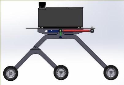
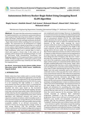
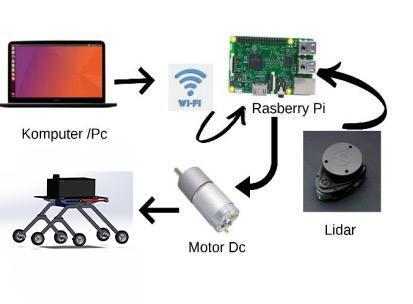
Inthisrobotweusealuminummaterialisusedforthebase platebecauseitisrigidandlightinweightandsteelmaterial forthelegstomorestableonroad.Weuse4motorsonthe frontandbackwheels.Onthetopoftherobot,weput the LIDARsensortogiveamoreaccuratereading.Motordrives areconnectedtothe4DCgearedmotorswhichareoperated at12voltsand100rpm.Themotordriveriscontrolledbya microcontroller,whichprovidesinstructionstothemotors accordingtothecommands.Theelectricalcomponentsare poweredbytwobatteries12V.Thewheeldiameterchosenis 10cmtosatisfytheefficienttravelingofthevehicleandit’s mostlyusedasastandardsizewheel.Thisisanautonomous systemwithnohumanintervention,whichhelpstheuserfor more accurate decisions. The flowchart of the robot operationsisshowninFigure2.
International Research Journal of Engineering and Technology (IRJET) e-ISSN: 2395-0056
Volume: 09 Issue: 08 | Aug 2022 www.irjet.net p-ISSN: 2395-0072
Figure 2: Flowchartdiagram
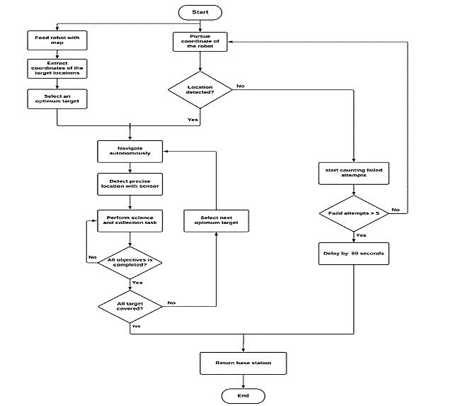
The Taguchi technique is a systematic design methodology that uses the design of experiments or simulationstoobtainanoptimalvalueforeachparameter.It is quite straightforward and cost-effective not only in establishing the objective function but also in satisfying many quality standards at the same time, as opposed to theoretical optimization approaches that often need complicated mathematical expansions. All key factors affecting performance measures like the signal-to-noise (S/N)ratiocanbecategorizedintotwocategoriesusingthis method:controlandnoisefactors.Thecontrolelementsare easy to alter to desirable levels since they can be set by a designer,whilethenoisefactorsarehardertoregulateand maycreatevariancesoradverseimpactsonproductquality. Therefore,suchparametersasthewheelradii(R1,R2,and R3) and the link lengths (l1, l2, l3, and l4) are selected as controlfactors,andthreestairsinFig3areselectedasnoise factors,respectively[28-31].
Taguchi methodology was originally developed for quality engineering, and the evaluation and improvement of a product’s robustness, tolerance specifications,andqualitymanagementoftheproduction process. We optimized the kinematic parameters of a rocker-bogie mechanism as a stair-climbing cart. The optimization was performed using the Taguchi methodology, and the sensitivity analysis results were presented.Constraintswereusedtodeterminetheinitial values of the parameters, and the constraints were checked after choosing the optimal parameters [32-34]. Optimal design is performed in two steps. First, an orthogonal array is used in each optimal design. Then, usingsensitivityanalysis,theoptimaldesignparameters aredetermined,andwewillshowthemintables.
Level of the design variable
G r3 F r2 E r1 D l4 C l3 B l2 A l1 Test number
1 1 1 1 1 1 1 1
2 2 2 2 2 2 1 2
3 3 3 3 3 3 1 3
3 3 2 2 1 1 2 4
1 1 3 3 2 2 2 5
2 2 1 1 3 3 2 6
3 2 3 1 2 1 3 7
1 3 1 2 3 2 3 8 2 1 2 3 1 3 3 9
1 2 2 3 3 1 1 10
2 3 3 1 1 2 1 11
3 1 1 2 2 3 1 12
2 3 1 3 2 1 2 13
3 1 2 1 3 2 2 14
1 2 3 2 1 3 2 15
2 1 3 2 3 1 3 16
3 2 1 3 1 2 3 17
1 3 2 1 2 3 3 18
International Research Journal of Engineering and Technology (IRJET) e-ISSN: 2395-0056
Volume: 09 Issue: 08 | Aug 2022 www.irjet.net p-ISSN: 2395-0072
L18( orthogonalarrayisusedbecauseit’ssimilar to the parameters that we will use. (J) Determined by experimentaccordingtothreekindsofstairstructures.We willdeterminethesignal-to-noiseratio(S/Nratio)from thatequation1.
S/N= (1)
Table 2: Objectivefunctionforeachstairshape
The objective function for each stair shape S/N ratio (dB) J3: 240x200 J2: 310x160 J1: 300x100
5.762 0.7515 0.4179 0.2376 7.201 0.5866 0.3757 0.2935 6.135 0.6909 0.4389 0.2457 7.253 0.5817 0.3742 0.2936 5.279 0.7694 0.4774 0.2639 6.166 0.7217 0.3858 0.2356 5.434 0.789 0.4432 0.1987 6.61 0.6348 0.4072 0.2932 5.425 0.7538 0.4718 0.2632 5.841 0.7156 0.4526 0.2545 6.084 0.7294 0.4096 0.1979 6.457 0.6512 0.4105 0.2927 6.115 0.6843 0.4422 0.2514 5.531 0.774 0.442 0.2125 7.715 0.5431 0.351 0.2992 7.083 0.5924 0.3624 0.324 5.832 0.7131 0.4562 0.258 6.166 0.7295 0.3865 0.209
The mean is determined to know the effect of the parametersontheresponseaccordingtoequation2.
Mean= (2)
Summing each squared deviation emphasizes the total deviation-squaresum(SS)canbecalculatedaccordingto equation3.
TablesshowtheMeanof18Testnumbers,soweneedto determineMeanTotal.ThemeantotalisequaltotheSum Meansof18testnumbers,Meantotalisequalto8.18.The sum of squares is a measure of the deviation of the experimental data from the mean value of the data.
(3) Table 4: SumofSquare(SS)
Sum square (ss) 3 2 1 Test number
3.7181 2.7618 2.7009 2.7173 A
3.72821 2.6931 2.7647 2.7222 B 3.71778 2.7278 2.7515 2.7007 C 3.73318 2.8675 2.5555 2.7571 D 3.71762 2.7086 2.7232 2.7482 E 3.72204 2.6666 2.6909 2.8225 F 3.71799 2.7552 2.6936 2.7312 G
There is a standard statistical technique called analysisof variance (ANOVA) that is routinely used to provide a measureofconfidence.Thetechniquedoesnotanalysethe datadirectly,butratherdeterminesitsvariability(variance). Thevarianceisusedtocalculateconfidence.Thevarianceof controllable and noise factors is provided by the analysis. Robust operating conditions can be predicted by understandingthesourceandmagnitudeofvariance.Thisis themethodology'ssecondadvantage[35].DOFisacrucial andvaluableconceptthatisdifficulttodefine.Itisameasure ofhowmuchinformationcanbedetermineduniquelyfroma givensetofdata.TheDOFfordataaboutafactorisoneless thanthenumberoflevels.Theexperimentcanalsobenefit from the concept of DOF. The concept of DOF can also be extendedtotheexperiment.Anexperimentwithntrialsand rrepetitionsofeachtrialhasn×rtrialruns.ThetotalDOF becomes[35].Variancemeasuresthedistributionofthedata about the mean of the data. Because the data are representativeofonlyapartofallpossibledata,DOFrather thanthenumberofobservationsisusedinthecalculation [35].
Variance= (4)
Source SS DOF Var. F(calc.) A 3.718 2 1.859 4.2762 B 3.7184 2 1.859105 4.27669 C 3.71778 2 1.85889 4.2757 D 3.73318 2 1.86659 4.3111 E 3.71762 2 1.85881 4.2753 F 3.72204 2 1.86102 4.2855 G 3.71799 2 1.85899 4.27617 Error 4.84898 3 1.61633
Total 30.8938 17
Factor value: 7.529 | ISO 9001:2008 Certified
International Research Journal of Engineering and Technology (IRJET) e-ISSN: 2395-0056
Volume: 09 Issue: 08 | Aug 2022 www.irjet.net p-ISSN: 2395-0072
Ata 90%confidencelevel,all oftheparametersare statisticallysignificantF2,3at90%=3.14
At95%confidencelevelparameterDisstatsignificant F2,3at95%=4.302
At99%confidencelevelnoneoftheparametersisstat significantF2,3at99%=9.55
Fromsignaltonoiseratioanalysistrial5hasthebest setting
FromANOVAanalysis,wefindthattheoptimaldesign intrial5isourdesign
AgearedDCmotor(Here)with63RPMand12Visused.The ratedtorqueis28.5kg-cm.Thismotorisusedtosatisfythe need off moving the whole vehicle. Since a lot of weight shouldbecarried,weusethistypeofmotor.Sixmotorsare usedhereandarecontrolledwithhelpofamotordriverand amicrocontroller.Themotorsarepoweredbya12Vbattery. Thewheeldiameterusedhereis20cm.Therearesixwheels usedhere.Thesewheelsaresufficienttotravelonalltypes ofroads.Withtherockerbogiemechanismandthedesignof thewheel,thevehiclecanmoveefficientlythroughtheroads. Thebaseplateoftherobotisaluminumbecauseitisrigid and light in weight, but the legs of the robot from steel becauseitisheavyandrigidtomorestabilityonroads Two 12V7.2Ahbatteriesareusedtopowerthefourmotorsand the microcontroller. This battery is efficient and rechargeable.Themicrocontrolleriscanbepoweredbythe samebatterybycontrollingthevoltagepassingthroughthe controller board. A battery is used because it is portable, Therefore the vehicle need not be powered with wires attachedusingtheelectricitythroughhouseholdlines.Atype ofmicrocontrollerboardthatisbuiltusingRaspberrypi4B–8GBmicrochipandArduino Mega based onATmega2560. Arduinoisanopen-sourceplatformforprototyping,andits simplicity makes it suitable for both hobbyists and professionalstouse.Thereare54digitalinput/outputpins on the Arduino Mega (of which 14 can be used as PWM outputs),anICSPheader,a16MHzcrystaloscillator,areset button,apowerjack,16Analoginputs,andaUSBinterface. This microcontroller board contains enough analog and digitalportswhichcanbeusedtointerfacethemotorsand sensors thatareusedinthe machine HereRPLIDAR A1 is basedonthelasertriangulationrangingprincipleanduses high-speed vision acquisition and processing, the system measuresdistancedatamorethan8000timespersecond. ThecoreofRPLIDARA1runsclockwisetoperforma360degree omnidirectional laser range scanning for its surroundingenvironmentandthengenerateanoutlinemap fortheenvironment[27]
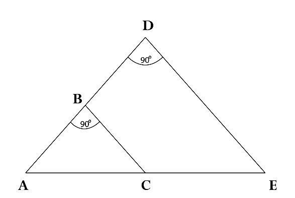
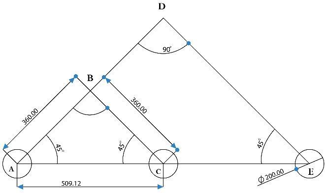
With the basic assumptions, the Rocker Bogie mechanism calculationsaremadeTheConstructionandConstraintsof RockerBogieMechanismAngleABCandADEisequalto , From the Isosceles Triangle formed, Constraints obtained areACisequaltoCE,ADisequaltoDE,angleDAEisequalto angleDEA equalto ,andAngleADEisequalto .To ensurethestabilityofclimbingobstacles,thepositionofone pairofwheelsatatimemustberaised.So,atfirst,wefind Bogielinksdimension
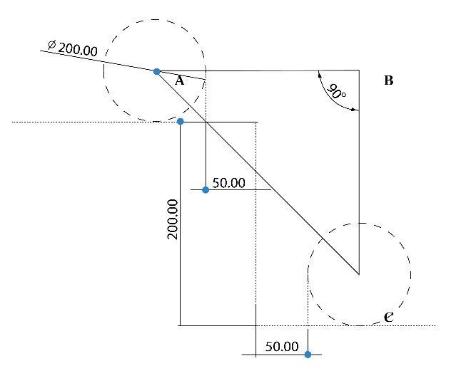
Wemakethesetupforcalculationasthefirstpairofwheels placed horizontally at the end of rising with 50mm extra space for safety purposes. on the same second pair is just beforethestartofraisingwith50mmextraspaceforsafety purposes
AB is equal to the sum of the Radius of wheel A, Safety SpaceA,SafetySpaceC,andRadiusofwheelC. ABisequal to 300 mm, and BC is equal to 150 mm. By Using PythagorasTheoreminTriangleABC
= + (5)
BytheCalculationsmade,thePrimaryLengthoftheBogie linkshouldbeofMinimallength150mmandawheelbase of335.4mm,byconsideringthemanufacturingcomplexity of the material the following Link length is taken for
International Research Journal of Engineering and Technology (IRJET) e-ISSN: 2395-0056
Volume: 09 Issue: 08 | Aug 2022 www.irjet.net p-ISSN: 2395-0072
furtherprocess,ABandBCwillbeequal360mm,ACwill beequalto509.12mm.
With the help of values obtained in Bogie links and constraintsdeveloped.WeconstructtheRockerLink.CEis equalto509.12mm,AEisthesumofACandCE,andAEis equalto1018.23mm,byusingTrigonometricEquations:DE isequalto720mm
Therequiredvaluesforproceedingwiththecalculationare listed below. The values that are mentioned below are standardvaluesandtheremainingvaluesaretakenfromthe abovecalculation
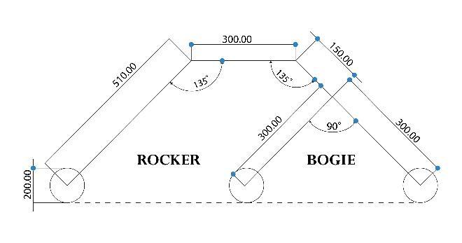
ThetopsurfaceoftheRockerBogieisneededto beflattofitthebox,motor,andbattery.So,wecutthetop edge of the Triangle ABC such that the height of the TriangleABCisgreaterthantheCutedgeheightfromthe base.TofindthelengthoftheXYbisectsline,weforma TriangleDXY Thelengthofhisequalto254.56mm
Nominalbotspeed (V) 0.5m/s
Maximumslopeincline(k) 15%
Totalrobotweight(m) 30kg Diameterofthewheel(Dw) 0.2m Co-efficientofdrag(Cd) 0.6 Densityofair(p) 1.226kg/m3
Co-efficientofrollingresistance(Crr) 0.01 FrontalArea(A) 0.158m2 Efficiencyofmotor 88%
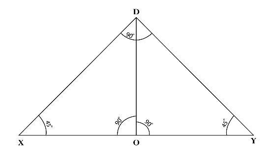
The length of DO is equal to the difference between the heightoftriangleADEandthebisectheightfromthebase, DOisequalto148.49mm.UsingTrigonometricEquations, XO is equal to 148 49 mm, OY is equal to 148.49mm Therefore,XYisequalto300mm ByalltheCalculations andDataobtained,weconstructtheRockerBogieLinks dimensions
Whenconsidering,theforcesactingonthetelepresence, the consideration of opposing forces that it has to overcome are taken into account. They are grade resistance,Dragresistance,androllingresistance.Thrust Force(Ft)isequaltothesumofthegraderesistance,Drag resistance,androllingresistance Graderesistanceisgiven astheproductoftheweightandthesineoftheangleof inclination. Grade resistance is equal to 44.145 N Drag force is the force that the vehicle has to move forward. This force increases with increasing speed. The Drag resistanceisequalto0.01452Naccordingtoequation6. (6) (7)
TheRollingresistanceisequalto2.943N Thetotalforce (Ft) is equal to the sum of the Grade resistance, Drag resistance, and Rolling resistance. The total force (Ft) is equalto47.1N.Torquefortractionwheel,peronewheel motor 2.355 Nm According to the standard dimensions available in the market, we select a motor of torque 28.5kg-cm available. We find the wheel rotation speed
International Research Journal of Engineering and Technology (IRJET) e-ISSN: 2395-0056
Volume: 09 Issue: 08 | Aug 2022 www.irjet.net p-ISSN: 2395-0072
valuetoevaluatetherpmofthemotor.Thenominalspeed oftherobotcanbecalculatedaccordingtoequation8.
(8) whereDwisthediameterofthewheel,Thenominalspeed of the robot is 50 RPM. According to the standard dimensions available in the market, we select a 63 rpm motor
Figure 11 Rockerstrainanalysis
Figure 12 Rockerstressanalysis
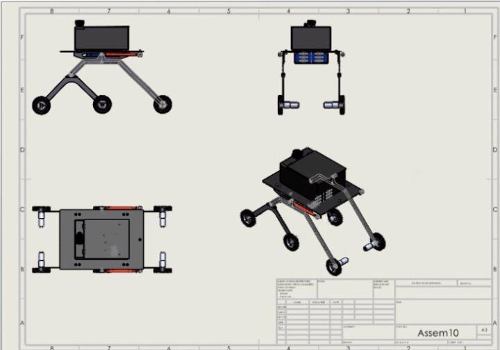
Figure 9 DrawingSheet
Figure 13 FOSOFRocker
Figure 10 Isometricviewin SolidWorks
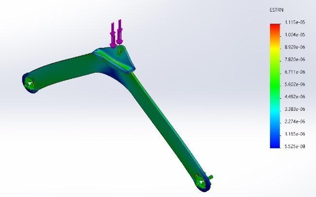
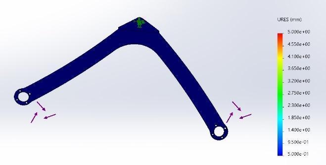
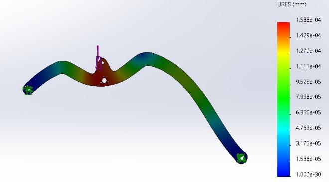
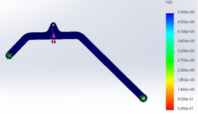
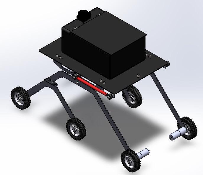
Figure 14 Bogie Stress analysis
International Research Journal of Engineering and Technology (IRJET) e-ISSN: 2395-0056
Volume: 09 Issue: 08 | Aug 2022 www.irjet.net p-ISSN: 2395-0072
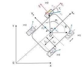
The configuration parameters and system velocities are defined as follows: ��, ��, ��, robot’s position (x, y) and its orientationangleθ(TheanglebetweenXand����);XGY, inertial frame; x,y are the coordinates of the reference pointOintheinertialbasis; ��rO��r,robot’sbaseframe; Cartesian coordinate system associated with the movement of the body center; ���� ���� ����, the coordinate systemofithwheelinthewheel’scenterpoint����;O,����, theinertial basisoftheRobotinRobot’sframeand ����= {������,������}thecenteroftherotationaxisofthewheel��; isa vector thatindicatesthedistance between the Robot’scenterandthecenterofthewheel��th;������,������,������, halfofthedistancebetweenfrontwheelsand������halfof thedistancebetweenthefrontwheelandtherearwheels ����,thedistancebetweenwheelsandthebase(centerofthe robotO);����,denotestheradiusofthewheeli(Distanceof the wheel’s center to the roller center) ���� , denotes the radiusoftherollersonthewheels.����,theanglebetween O���� and XR ; ���� , the angle between S i and XR ; ���� , the angle between ������ and ���� ; ���� [rad/s], wheels angular velocity;������[��/��],��=0,1,2,3∈��,isthevelocityvector correspondingtowheelrevolutions ������,thevelocityof the passive roller in the wheel i; [������ ������ ωi ] T , Generalizedvelocityofpoint����intheframe������������;[������ ������ωi]T,Generalizedvelocityofpoint ����intheframe ����������;��x,��y[m/s]-Robotlinearvelocity;����[rad/s]Robotangularvelocity;
AccordingtoequationsforForwardandInverse kinematicsthereis:
��1=1/��(����−����–(����+����)��),
��2=1/��(����+����+(����+����)��), ��3=1/��(����+����–(����+����)��), ��4=1/��(����–����+(����+����)��).
LongitudinalVelocity: ����(��)=(��1+��2+��3+��4).r/4 (9)
TransversalVelocity: ����(t)=(−��1+��2+��3−��4).r/4 (10)
Angularvelocity:
����(��)=(−��1+��2−��3+��4).��/4(����+����) (11)
The resultant velocity and its direction in the stationery coordinate axis (x, y, z) can be achieved by the following equations
V��= (12)
InROSimplementationalaptopmachineLenovo-Legon7i slim[Intel(R)Core(TM)i7-11750HQCPU@4GHz]With 16GBRamandworksasamastercomputeroperatedwith Linux(Ubuntu)version18.04operatingsystem.Thereisa slavemachinethatworkswiththemastermachinewhich isRaspberryPi4BrunningUbuntu-mate18.04[36].
The robot operating system (ROS) is Linux-based, it is a flexibleframeworkforcreatingrobotsoftware.itconsistsof tools,libraries,andprotocolsthataimtosimplifyandcreate complexrobotbehavioracrossnumerousroboticsplatforms [36].ROSstructureconsistsofpackagesandnodesthatare usedtobuildacompleteworkspacefortherobot,tobuild the strategy that is followed to build a robot in ROS is to create Nodes to connect to the controller to the ROS environment,whilethecomponents,mapping,localization andmove_basenodesareimplementedbyC++andpython sharedlibrariesthatgetlinkedtothenodeatcompilingtime.
ROS structure allows the tracked robot to link and synchronizemessagesbetweennodesinthemastermachine andwithRaspberry-pi4boardonboardclientcomputerand micro-controllerintherobotbythenetworkusingroscore
International Research Journal of Engineering and Technology (IRJET) e-ISSN: 2395-0056
Volume: 09 Issue: 08 | Aug 2022 www.irjet.net p-ISSN: 2395-0072
mastercomputer.Thenodescontacteachotheraccordingto topicsandarecollectedanddescribedthroughtheROSgraph diagramasshowninfigure17.Itdisplaysseveralnodesand topicstocontroltrackedrobotautonomoussystems.Graphof ROS nodes came in the shape of (ellipses) and topics (squares)of the proposed trackedvehicle. The continuous line arrows are topic subscriptions, that moved from the subscriber node to publish it into another node with directionsgoingfromthesubscribernodetothepublisher one.

Forlinksandjointsofthetrackedrobotautonomoussystem, itiscreatedbyUnifiedRobotDescriptionformatURDFthat described in ROS transformation tree frames diagram It shows all the frames involved in the architecture of the system,thatshowninfigure18.
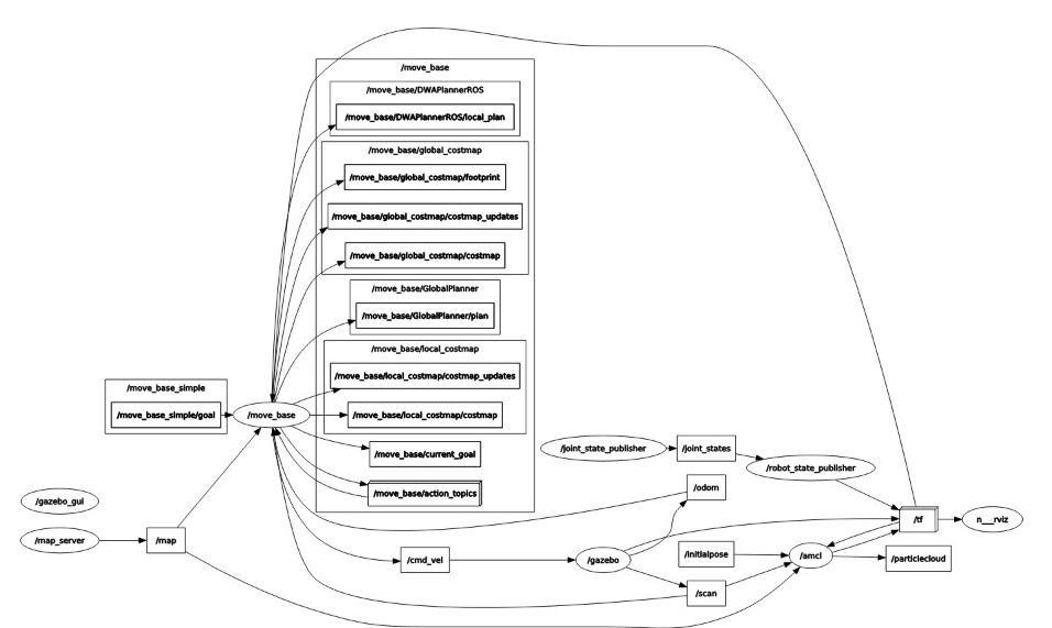
Figure 18 ROStransformationtreeframesdiagramrqttf tree
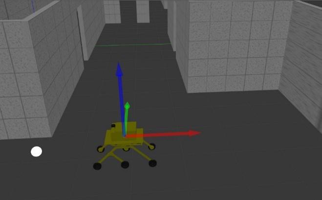
TheUnifiedRoboticDescriptionFormat(URDF)isanXML fileformatusedinROStodefineallofarobot'scomponents. In order to use a URDF file in Gazebo, some additional simulation-specific tags must be added. This section describestheessentialstepstosuccessfullyuseyourURDFbasedrobotinGazebo,savingyoufromhavingtogeneratea separateSDFfilefromscratchandduplicatingdescription formats.Underthehood,GazebowillthenconverttheURDF toSDFautomatically[36].Thefirststeptogettingyourrobot workinginGazeboistohaveaworkingURDFfiletherefore we used the approach of creating a cad design using the Solidworkscaddrawingprogramandthenconvertingthe CADmodelintoURDFformatbyURDFEXPORTERandthen put it in an XML file format. If the URDF is created and suitableasastandardformatforGazeboitwillbedisplayed in Gazebo as shown in figure 19, Therefore, after the transformationofCADdesignofURDFfileformatishandled andsetbyusingthevisualstudiocodeprogram.
Figure 19 URDFdisplayingingazeboworld
International Research Journal of Engineering and Technology (IRJET) e-ISSN: 2395-0056
Volume: 09 Issue: 08 | Aug 2022 www.irjet.net p-ISSN: 2395-0072
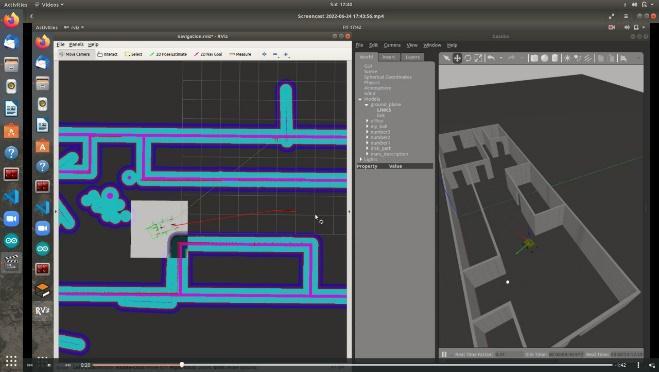
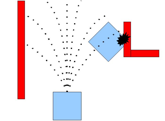
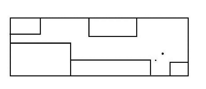
Using slam-gmapping, you can create a 2-D occupancy gridmap(likeabuildingfloorplan)fromthelaserandpose data collected by a mobile robot. (Light Detection and Ranging),posedataisgainedthroughbase-linkposition,and according to Laser data is obtained from laser scans produced by LIDAR these data the robot can calculate the nearestobstaclepositionregardingtherobot’sposition,and itdrawsamapwiththisgiveninformation
toa newsaferpathfurthermoreitoperatesin a local cost map.
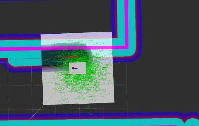
Amclisaprobabilisticlocalizationsystemforarobotmoving in2D.ItimplementstheadaptiveMonteCarlolocalization approach,whichusesaparticlefiltertotracktheposeofa robotagainstaknownmap[37]AccordingtoMonteCarlo’s localization principle, the robot assumes many positions withvariousorientationsthesesamplesarefilteredtofind thecorrectpositionwiththecorrectorientationsothatthe robotcanidentifyitsrightposition.
The dwa local planner package contains a controller for controlling a mobile base in the plane. This controller is responsibleforconnectingthepathplannertotherobot.The plannerusesamaptocreateakinematictrajectoryforthe robot to follow from start to finish. Along the way, the plannergeneratesavaluefunction,whichisrepresentedasa grid map, at least locally around the robot. The costs of traversingthegridcellsareencodedbythisvaluefunction
Thecontroller'sjobistousethisvaluefunctiontodetermine dx,dy,dthetavelocitiestosendtotherobot.
given a goal in the world, will attempt to reach it with a mobilebase.Themove-basenodelinkstogetheraglobaland localplannertoaccomplishitsglobalnavigationtask[37]. Where the global planner is the algorithm responsible for makingtheoriginalpathtoreachitsgoal accordingtothe global costmap, whilethelocal planneris responsible for recheckingifthispathisstillsafeifnotitredirectstherobot
This paper presented an autonomous navigation delivery system of the Rocker and Bogie mechanism. The designofthemechanismandcomponentselection,andfinite elementanalysisweresummarized.Themainadvantageof the presented system is its capability to adapt to road segments of different curvatures and the transitions betweenthem.Therocker-bogiemechanismisoptimizedvia the Taguchi method to improve its climbing capability as wellasadaptabilityforvarioustypesofstairs.Moreover,to guaranteethestablebehavioroftheproposedrocker-bogie mechanism during climbing of the stair more rapidly and
International Research Journal of Engineering and Technology (IRJET) e-ISSN: 2395-0056
Volume: 09 Issue: 08 | Aug 2022 www.irjet.net p-ISSN: 2395-0072
efficiently.Finally,theobtainedsimulationandexperimental results show the efficiency of the proposed robot. Future workslieinimplementingunderROSmorecomplicatedand sophisticatedcontrollermethodsaswellasimprovingthe vehicle’sself-localization
The study was supported by the Canadian International College, 5th Settlement, Cairo, Egypt. The authors express theirgratitudetothissupportiveinstituteandthesupervisor who provided invaluable advice and suggestions to this study.
[1]S.Fish,UGV'sinfuturecombatsystems,Proceedingsof theSPIE-unmannedGroundVehicleTechnologyVI,Orlando, USA,2004,pp.288–291.
[2] F.L. Menn, P. Bidaud, F.B. Amar, Generic differential kinematicmodelingofarticulatedmulti-monocyclemobile robots, Proceedings of the 2006 IEEE International Conference on Robotics and Automation, Orlando, USA, 2006.
[3]A.Halme,I.Leppanen,J.Soumela,S.Ylonen,I.Kettunen, Workpartner: interactive human-like service robot for outdoor applications, International Journal of Robotics Research22(2003)627–640.
[4] C. Distante, G. Indivery, G. Reina, An application of mobile robotics for olfactory monitoring of hazardous industrialsites,IndustrialRobot:AnInternationalJournal36 (2009)51–59.
[5] R. Volpe, J. Balaram, T. Ohm, R. Ivlev, Rocky7: a next generation Mars rover prototype, Advanced Robotics 11 (1997)341–358.
[6]R.A.Lindemann,C.J.Voorhees,Marsexplorationrover mobility assembly design, test and performance, IEEE InternationalConferenceonSystems,ManandCybernetics, Waikoloa,USA,2005.
[7]J.Erickson,Livingthedream:anoverviewofthemar’s exploration project, IEEE Transactions on Robotics and Automation13(2006)12–18.[8]B.Chen,R.Wang,Y.Jia,L. Guo,L.Yang,Designofahigh-performancesuspensionfor lunarroverbasedonevolution,ActaAstronautica64(2009) 925–934.
[9]A.Mechdari,H.N.Pishkenari,A.L.Gaskarimahalle,S.H. Mahboobi,R.Karimi,Anovelapproachforoptimaldesignof a rover mechanism, Journal of Intelligent and Robotic Systems44(2005)291–312.
[10] K. Nagatani, A. Yamasaki, K. Yoshida, T. Adachi, Development and control method of six-wheel robot with rockerstructure,Proceedingsofthe2007IEEEInternational WorkshoponSafety,SecurityandRescueRobotics,Rome, Italy,2007.
[11]W.Chung,G.Kim,M.Kim,DevelopmentofthemultifunctionalindoorservicerobotPSRsystems,Autonomous Robotics22(2007)1–17.
[12]M.Wada,M.Wada,Mechanismandcontrolofa4WD robotic platform for omnidirectional wheelchairs, Proceedingsofthe2009IEEE/RSJInternationalConference onIntelligentRobotsandSystems,St.Louis,USA,2009.
[13] F. Michaud, et al., Multi-modal locomotion robotic platform using leg-track-wheel articulations, Autonomous Robots18(2005)137–156.
[14]D.Chugo,K.Kawabata,H.Kaetsu,H.Asama,T.Mishima, Step climbing omnidirectional mobile robot with passive linkages, Proceedings of SPIEoptomechatronic Systems Control,Sapporo,Japan,2005.
[15]S.Nakajima,Developmentoffour-wheel-typemobile robotforroughterrainandverificationofitsfundamental capabilityofmovingonroughterrain,ProceedingsofIEEE International Conference on Robotics and Biomimetics, Bangkok,Thailand,2009.
[16] R. Siegwart, P. Lamon, T. Estier, M. Lauria, R. Piguet, Innovativedesignforwheeledlocomotioninroughterrain, RoboticsandAutonomousSystems20(2002)151–162.
[17]S.Nakajima,Conceptofanovelfour-wheel-typemobile robot for rough terrain, RT-mover, Proceedings of IEEE InternationalConferenceonIntelligentRobotsandSystems, St.Louis,USA,2009.
[18] Manash Dey, Harshit Bisht, Rishab Kumar, Abhinav Kumar, Aman Arora, Jatin, “Rocker Rover and Its Implementation in the Field of Agriculture: A Review”, JournalofEmergingTechnologiesandInnovativeResearch, Volume6,Issue6,June2019.
[19].Hong-anYang,LuisCarlosVelascoRojas*,ChangkaiXia, QiangGuo,SchoolofMechanicalEngineering,Northwestern PolytechnicUniversity,Xi’an,China,DynamicRocker-Bogie: AStabilityEnhancementforHigh-SpeedTraversal-Vol.3, No.3,September2014,pp.212~220ISSN:2089-4856
[20] P. Panigrahi, A. Barik, Rajneesh R. & R. K. Sahu, “IntroductionofMechanicalGearTypeSteeringMechanism to Rocker Bogie”, Imperial Journal of Interdisciplinary Research(IJIR)Vol-2,Issue-5,ISSN:2454-1362,2016.
[21]Fernández,E.,Crespo,L.S.,Mahtani,A.,&Martinez,A. (2015). Learning ROS for robotics programming. Packt Publishing.
2022, IRJET | Impact Factor value: 7.529 | ISO 9001:2008 Certified Journal |
International Research Journal of Engineering and Technology (IRJET) e-ISSN: 2395-0056 Volume: 09 Issue: 08 | Aug 2022 www.irjet.net p-ISSN: 2395-0072
[22]M.D.Manik,A.S.Chauhan,S.Chakraborty,V.R.Tiwari, “Experimental Analysisofclimbingstairswiththerockerbogie mechanism”, Vol-2 Issue-2 P.No. 957-960IJARIIEISSN(O)-2395-4396,2016.
[23]Mogg,T.(2018).Startupinks‘world’slargestdeal’for driverless grocery deliveries. Digital Trends. https://www.digitaltrends.com/cars/autonomous-grocerydelivery-on-its-way-to-oklahoma-city/ Accessed July 1, 2018.
[24]Starship(2017).StarshipTechnologieslaunchespilot program with Domino’s Pizza Enterprises, https://www.starship.xyz/press_releases/starshiptechnologies-launches-pilot-program-with-dominos-pizzaenterprises/AccessedJuly25,2018.
[25] Starship (2018). Starship Technologies Launches Commercial Rollout of Autonomous Delivery. https://www.starship.xyz/press_releases/starshiptechnologies-launches-pilot-program-with-dominos-pizzaenterprises/AccessedJuly1,2018.
[26]Jennings,D.,andFigliozzi,M.(2019).AStudyofRoad AutonomousDeliveryRobotsandTheirPotentialImpactson Freight Efficiency and Travel, Submitted and presented at Transportation Research Board 99th Annual Meeting. January 2020, Washington DC. Kershner, R. (1939). The number of circles covering a set. American Journal of mathematics,61(3).
[27]https://www.slamtec.com/en/Lidar/A1
[28]B.K.Rout,R.K.Mittal,Parametricdesignoptimizationof 2-DOF R–R planar manipulator a design of experiment approach,RoboticsandComputerIntegratedManufacturing 24(2008)239–248.
[29]H.Kim,D.Kim,H.Yang,K.Lee,K.Seo,D.Chang,J.Kim, Developmentofawall-climbingrobotusingatrackedwheel mechanism,JournalofMechanicalScienceandTechnology 22(2008)1490–1498.
[30]K.Lee,J.Kim,Controllergaintuningofasimultaneous multi-axis PID control system using the Taguchi method, ControlEngineeringPractice8(2000)949–958.
[31] G.S. Peace, Taguchi Methods: Hands-on Approach, Addison-Wesley,NewYork,1993
[32]S.-H.Baek,S.-H.Hong,S.-S.Cho,D.-Y.JangandW.-S.Joo, Optimization of process parameters for recycling of mill scale using Taguchi experimental design, Journal of MechanicalScienceandTechnology,oct2010,2127-2134.
[33]H.-K.Kim,J.-Y.Jeon,J-Y.Park,S.YoonandS.Na,Noise reductionofahigh-speedprintingsystemusingoptimized gears based on Taguchi’s method, Journal of Mechanical ScienceandTechnology,dec20102383-2393.
[34]H.Shin,S.Lee,W.In,J.I.JeongandJ.Kim,Kinematic optimizationofaredundantlyactuatedparallelmechanism for maximizing stiffness and workspace using Taguchi method,JournalofComputationalandNonlinearDynamics, jan2011.
[35]R.K.Roy,AprimerontheTaguchimethod.Societyof ManufacturingEngineers,2010.
[36] Quigley, M., Gerkey, B., & Smart, W. D. (2015). Programming robots withROS: A practical introductionto therobotoperatingsystem.O'ReillyMedia.
[37]Fernández,E.,Crespo,L.S.,Mahtani,A.,&Martinez,A. (2015). Learning ROS for robotics programming. Packt Publishing.
2022, IRJET | Impact Factor value: 7.529 | ISO 9001:2008 Certified Journal