International Research Journal of Engineering and Technology (IRJET)

e-ISSN:2395-0056
Volume: 09 Issue: 08 | Aug 2022 www.irjet.net p-ISSN:2395-0072
Modeling andAnalysis of a 3-Phase 132kv GasInsulated Substation
Abstract: This paper introduces Modeling of a 3- Phase 132kv Gas Insulated Substation.Such over voltagescancausemalfunctioningofprotectioncircuits and control circuits and also initiates faults and influence on other components such as transformers.Fordesigningasubstationitisessentialto know the maximum value of VFTO.Hence studies are carried out on estimation of the VFTO levels.For this purpose MATLAB 7.8 can be used.In MATLAB 7.8 simulation a suitable equivalent circuit is necessary for eachcomponent ofthesubstation.AnalysisofVery Fast Transient Overvoltage has been carried out using MATLAB7.8 for various switching conditions in a 3phase132kVgasinsulatedsubstation.
Keywords , MATLAB 7.8 software and Control circuitry,Gas Insulated Substation (GIS), Very Fast Transient overvoltages, Switching operations, 3 phase fault
I. INTRODUCTION
Gas Insulated Substations (GIS) have found a broad range of applications in power systems over the last three decades because of their high reliability, easy maintenance, small ground space requirementetc.. In ourcountryalso,a fewGISunitshavebeeninoperation and a large number of units are under various stages of installation[1].
GIS is based on the principle of operation of complete enclosure of all energized or live parts in a metallic encapsulation, which shields them from the external environment[2].Compressed SF6 gas, which has excellent electrical insulating properties, is employed as the insulating medium between the encapsulation and the energized parts.Gas Insulated Substations have a grounded outer sheath enclosing the high voltage inner conductor unlike conventional equipmentwhoseclosest groundistheearthsurface[3][4].
The Basic Insulation Level (BIL) required for a Gas Insulated Substation (GIS) is different from that of the conventional substation because of certain unique properties of the former[5].Gas insulated bus has a surge impedance (70
Ohm)morethanthatoftheconventionaloilfilledcables, but much less than that of a over head line (300 – 400 Ohms)[6].
In addition, the GIS is totally enclosed and therefore is free from any atmospheric contamination.Hence, in general the GIS permit lower BIL rating than the conventional one.A GIS requires less number of lightning arresters than a conventional one[7]. The representation of bushing is important for simulatingthefasttransients.Generally,thetransittime through a bushing is comparable to or greater than the rise time of GIS generated transients.For this reason, bushings cannot be considered as a lumped element in estimatingtheVFTOlevel.
The generation of fast transients can be classified into twotypes.Theyareduetothefollowing:
a) Dis-connector switch operation b)FaultsbetweenBusbarandEnclosure
In case of 3-phase fault, the voltage collapse at the fault location occurs in a similar way as in dis-connector gap during re-striking.By this event, step shape traveling surges are injected.For such a surge source inside GIS, two surges traveling in opposite directions are generated.However, if voltage collapse occurs at the open end of GIS, only single surge propagates on the bus[8].
During recent field tests on a 132KV substation, measurements were made of the trapped charge left when a DS was opened onto a floating section of switchgear.Numerous measurements led to the conclusionthatforthisswitch,apotentialof0.1 –0.2p.u is left on the floating section and that this result is consistent[9][10].
II. ESTIMATION OF 132KV GAS INSULATED SUBSTATION
During the switching operation of the circuit, the transientsaredeveloped.By thecalculatedvaluesof the circuit parameters in previous chapter, the equivalent circuits are constructed by using MATLAB 7.8 software.By using the circuits the transients are calculated for different lengths of Gas insulated substation. Thetransientsare alsocalculated duringthe faultswithandwithoutloadatdifferentdistances.
© 2022, IRJET | Impact Factor value: 7.529 | ISO 9001:2008 Certified Journal | Page1467
Lalit Patil1 , Jigisha Ahirrao2 , Mangesh Mondhe3 & Roshni Patil4International Research Journal of Engineering and Technology (IRJET) e-ISSN:2395-0056
Volume: 09 Issue: 08 | Aug 2022 www.irjet.net p-ISSN:2395-0072
During the current operation of dis-connector switch in a GIS, re-strikes(pre-strikes) occur because of low speed of the dis-connector switch moving contact, hence Very fast Transient Over voltage are developed. These VFTO‘s are
caused by switching operations and 3-phasefault in 132KvGIS UsingMATLABoftheequivalentmodelsis developed.
A. Spacers capacitance

The spacer existed with finite thickness and develops some amount of capacitance in addition with existed capacitance. Spacers are used for supporting the inner conductorwithreferencetotheouterenclosure.Theyare made with Alumina filled epoxy material whose relative permittivity(εr)is4.
B. Calculation of short circuit inductance &Resistance:
An d %Z
D. Inductance calculation
Theinductanceofthe bus ductcanbecalculatedby usingtheformula[8]givenbelow,wherer1,r2,r3,r4, are the radii of the conductors in the order of decreasing magnitude and ‗l‘ is the length of the section. ����(��1)+����(��2)+����(��4) + =0.001×��×l ��3 ��2 2 ��1 ��3
Assuming a short circuit fault level of 1000 MVA for 220KV system voltage, inductance and resistance are calculatedasfollows: 2× (��1) �� (��1) ×����(��1 1) ��2 l
Calculationofvariablearcresistance:
using
R(t)
calculated until it reaches a value of 1 to 3 ohms. The integral in the denominator sums up the absolute valueofcurrent‗i‘throughtheresistanceR(t)overthe time beginning at breakdown inception. Thus, it corresponds to the charge conducted through the sparkchanneluptotime‗t‘.
Initial charge qo is an important parameter while considering the non-uniform fields. But the field betweenthedis-connectorcontactsisalmostuniform. Thereforeqo isverysmall.
International Research Journal of Engineering and Technology (IRJET)
e-ISSN:2395-0056
Volume: 09 Issue: 08 | Aug 2022 www.irjet.net p-ISSN:2395-0072
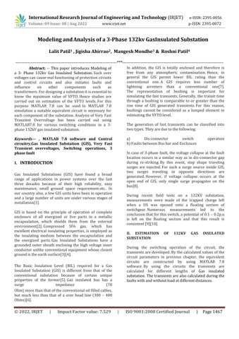
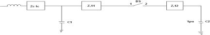
Fig1.EquivalentcircuitofGIS
Fig.2.Equivalentcircuitfor10mtrs.Lengthina3-phase to132kvGIS
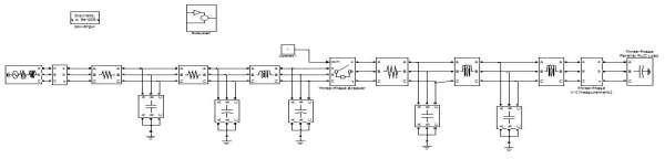
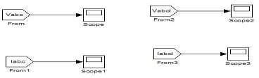
Fig.3.MATLAB circuitfor10mtrslengthina3-phaseto132KVGIS
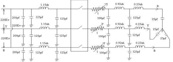
Fig.4.SubCircuitof132kVGIS © 2022, IRJET | Impact Factor value: 7.529 | ISO 9001:2008 Certified Journal | Page1469
International Research Journal of Engineering and Technology (IRJET)
e-ISSN:2395-0056
Volume: 09 Issue: 08 | Aug 2022 www.irjet.net p-ISSN:2395-0072
II. EQUIVALENT CIRCUIT FOR 132KV GIS SYSTEM
This circuit is divided into three sections of 1mtr, 4mtrs and 5mtrsrespectively fromloadsideand by usingthecircuit
shownbelowfigure1 &2.
The Fast transient over voltages are generatednot only due to switching operations but also due to 3-phase fault in 132Kv GIS .The bus duct is dividing into three sectionsoflengthfromloadside.
The GIS bushing is represented by a capacitance of 200pf.Theresistanceof1ohmsparkchannelisconnected inseries withcircuitbreaker.MATLABCircuitfor10mtrs. lengthina3-phase132KvGISshowninthe fig.3andSub Circuitof132kVGISfig.4.
The proposed method implemented on MATLAB 7.8. the voltage before and after circuit breaker is taken to be 1.0 p.u and -1.0pu as the most enormous condition but depending on the time of closing of circuit breaker the magnitudeofthevoltageontheloadsidechanges.
Fordifferentvaluesofvoltagesontheloadsidethe magnitudes and rise time of the voltage wave are calculated keeping source side voltages as constant as 1.0p.uthevaluesaretabulatedintableI.
Similarly by changing the magnitudes of the voltage onthesourceside,keepingvoltageonloadsideconstantat 1.0p.u. Then the transient due to variation of voltage on sourcesideobtained.ThevaluesaretabulatedinTableII.
TABLEI
TRANSIENTDUETOVARIATIONOFVOLTAGEON LODESIDE

TABLEII
TRANSIENTSDUETOVARIATIONOFVOLTAGEON SOURCESIDE
S.no Load side Voltage (p.u)
Magnitude of the voltages (p.u) Rise Time (Nanosecs)
VR phase VY phase VB Phase tr ty tb
1 1 0 2 41 2 40 2 42 10 09 10
2 0 9 2 36 2 36 2 33 11 12 11 3 0 8 2 23 2 22 2 21 12 11 12 4 0 7 2 03 2 04 2 03 11 10 11
5 0 6 2 04 2 05 2 02 13 12 13
6 0.5 1.79 1.78 1.77 12 11 11
7 0.4 1.71 1.70 1.69 11 10 12 8 0 3 1 61 1 60 1 62 12 11 11 9 0 2 1 48 1 47 1 46 10 11 10 10 0 1 1 36 1 35 1 36 09 10 11
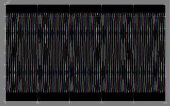
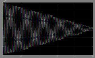
Fig. 5 Current waveform during closing operation of CB for 10mtslengthina3-phase132kvGIS
III. RESULTS AND DISCUSSION
The various current and transient voltage at different positions in a 3-phase 132kv GIS for the first switching operationpresentedinresults.
The variable arc resistance is calculated by using the Toepler‘sformula.Theinductanceofthebusbarisfoundout from the diameters of conductors and enclosure.The bus capacitance is calculated using formula for concentric cylinders.
Volume: 09 Issue: 08 | Aug 2022 www.irjet.net p-ISSN:2395-0072
The maximum values of VFTO, the MATLAB7.8 software is used and a simulation is carried out by designing suitable equipment circuits and its models are developed.The main advantages of such models are used to enable the transient analysisinGIS.
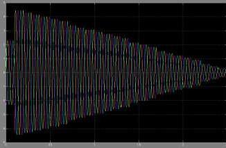
During closed operation, the current through the resistance ofthecircuitbreakerisshowninfig.5Fromthegraphitwas foundthemaximumcurrentis35Aatarisetimeof14ns.The transientsduetoclosingofthecircuitbreakerarecalculated as shown in fig 6. From this graph, the peak voltages obtained are 2.44, 2.43 and 2.44p.u at rise times of 69, 68.69nsrespectively.
The transients due to switching operations and line to enclosure faults with fixed arc resistance for different lengths of GIS are found. Transients are calculated along with load and it was observed that the transients obtained in 5mts length GIS will effect the system more than thatobtained in 10mts length GIS. As the distance between the fault point and load increases during fault analysis the magnitudes and rise times of the transients also increases. and2.54p.uatarisetimeof122,121and 123nsrespectively.
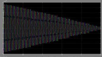
Fig.7Transientvoltagewaveformduringopening operationofCBfor10mtslengthina3-phase 132kvGIS
Assuming a second re-strike occurs the transients are calculatedbyclosinganotherswitchatthetimemaximum voltage difference occurs across the circuit breaker. The transients obtained due to second re-strike are shown in Fig8
Fig6Transientvoltagewavefromduringclosing operationofCBfor10mtslengthina3-phase 132kvGIS
To introduce current chopping the circuit breaker is opened. The transients obtained during opening operation are shown in Fig 6.4. From the graph, the maximumvoltagesobtainedare1.23,1.22and1.21p.u.at risetimesof61,60,and61nsrespectively.MATLABCircuit for 10mtrs. Length in a 3- phase 220kv GIS shown in the fig3
Fromthegraph,themaximumvoltagesobtainedis 2.51,2.52 for10mtslengthina3-phase132kvGIS
The magnitudes and rise times of 10mts length GIS aretabulatedinthetableIII.
Fig.8Transientvoltagewaveformduringsecond re-strikes
International Research Journal of Engineering and Technology (IRJET) e-ISSN:2395-0056
Volume: 09 Issue: 08 | Aug 2022 www.irjet.net p-ISSN:2395-0072
TABLEIII
Mode of operatio n
Magnitude of voltages(p.u )
Rise time (Nano sec)
VR phase VY phase VB phase tr ty tb
During closing operation 244 243 244 69 68 69 During opening operatio n
123 122 121 61 60 61 During secondrestrike 251 252 254 122 121 123
III. CONCLUSION
The fast transient over voltages that are obtained due to switching operations in GIS are simulated.. It is observed that the peak magnitudes are 26% to 30% higher in case of disconnector switch closing operation. With effective design and use of the same can effectively reduce the steepness and maximumpeakofVFTOgenerated.
The fast transient over voltages are obtained dueto switching operations and short-circuit faults are studied. The transients are calculated initially with fixed arc resistance and then variable arc resistance. The variable arc resistance is calculated by using Toepler‘s formulae. Transients along with load and withoutloadarealsoestimated.
IV. REFERENCES:
[1] S. Nishiwaki, Y. Kanno, S. Sato, E. Haginomori, S. Yamashita,andS. Yanabu, ―GroundFaultbyRe-striking Surge of SF6 Gas insulated Disconnecting Switch and Its Synthetic Tests,‖ – Transactions on Power Apparatus andSystems,vol.PAS-102,No.1,pp.219-227,1983.
[2] N. Fujimoto and S. A. Boggs, ―Characteristics of GIS Disconnector-induced Short Rise time Transients Incident on Externally Connected Power System Components,‖IEEE 87 WM 185-2,New Orleans, Feb. 1987.
[3] W. Boeck and W. Taschner, ―Insulating Behavior of SF6 with and without Solid Insulation in Case of Fast Transients,‖ CIGRE Paper No.1547, Aug. 1986. TransactionsonPowerSystems,vol.PWRD-1,No.2,pp. 95-101,1983.
[4] R. Witzman, ―Fast Transients in Gas Insulated Substations (GIS) – Modeling Of Different GIS Components,‖ Fifth International Symposium on High Voltage Engineering, No.12.06,1987.
[5] J. Lewis, B. M. Pryor, C. J. Jones, T. Irwin, ―Disconnector Operations in Gas Insulated Substations OvervoltageStudiesandTestsAssociatedwitha420 kV Installation‖,CIGRE,Vol.11, 1988, paper 33.09, pages18
[6] M.kondalu, G.Sreekanthreddy, Dr. P.S. subramanyam,‖ Analysis and Calculation of very fast transientovervoltagesin220kvgasinsulatedSubstation International Journal of Engineering &techsciencevol 2(4)2011
[7] M.kondalu, , Dr. P.S.subramanyam ―Estimation of Re-striking Transient Over voltages in a 3-phase 132kv Gas Insulated substation published in International journal of Advanced Research in Computer Engineering & Technology Issue4-Volume1-series1,pages 22-27 ,June-2012
[8] M.kondalu, , Dr. P.S. subramanyam ―Calculation of TransientsatDifferentDistancesinasinglephase220kv Gas Insulated substation published in International journal of Advanced Research in Computer Engineering & Technology Issue4-Volume1pages 28-33 – June-2012
[9] H. Hiesinger,RWitzmann.Very fast Transient Breakdown at a needle Shaped Protrusion, IX Int. Conf.onGasDis.andTheirAppli.Sep1988.
[10] M.kondalu, G.Sreekanthreddy, Dr. P.S.subramanyam,‖ Estimation Transient overvoltages in gas insulated bus duct from 220kv gas insulated substation‖, International journal of Computer applications,(0975-8887)volume20-no.8april2011.