International Research Journal of Engineering and Technology (IRJET) e-ISSN: 2395-0056

Volume: 09 Issue: 08 | Aug 2022 www.irjet.net p-ISSN: 2395-0072
International Research Journal of Engineering and Technology (IRJET) e-ISSN: 2395-0056
Volume: 09 Issue: 08 | Aug 2022 www.irjet.net p-ISSN: 2395-0072
Manpreet Kundra1 , Pradyumna Dashora2
1M Tech, FOE, PAHER University, Udaipur 2Assistant Professor, FOE, PAHER University, Udaipur ***
Abstract - With a boom in urbanization, the use density of underground areas in predominant towns is regularly increasing, and the congestion of underground areas is turning into more and more prominent. A comparative analysis is also made between the proposed pile foundation material and conventional material. The parametric optimization is performed to determine the effective relationship between dependent and independent variables. Taguchi method, ANOVA techniques are applied on the structure to obtain various parameters optimization. It was observed that the Intensity of displacement in each pile design combination showed an increase with the enhancement in the intensity of blast loads. The maximum displacement of 3.98 mm happens at 2495 N load while at 195 N load the maximum displacement was 1.238 mm. Also, it was further noted in the study that Intensity of stresses in each pile design combination showed an increase with the enhancement in the intensity of blast loads. The maximum displacement of 3.98 mm happens at 2495 N load with 2460 N/mm2 while at 195 N load with 212 N/mm2 the maximum displacement was 1.238 mm. Pareto analysis shows the blast load applied has more significant impact than the pressure applied over the area in performance of the structure with respect to the maximum deviation of the structure.
Key Words: PileDesign,ANSYS,Optimization,Taguchimethod,ANOVAUnderground rail transit has evolved into one of the primary modes of transportation as a result of the growth in urban population[1].Themajorityofsubwaystations,whichserveasthetransportationcentersforundergroundrailsystems,are foundindenselypopulatedurbanareaswithchallengingterrain.Groundsurfacesettlementduringconstructionisoneofthe most significant concerns that plague subway stations frequently [2-4]. These structures frequently have deep piling foundations,whichcanhinderthedevelopmentofundergroundstructureslikesubwaysandotherpipes[5].Formanyprojects, includinghigh-risebuildings,pilefoundationshavebeenbuilt.However,currently,studiesonpilefoundationunderpinningera specializesinthelayoutandoptimizationoftheunderpinningscheme,andresearchatthecorrespondingpressureswitch mechanismanditseffectonsubwaytunnel productionarelimited.Moreover,thetunnel productionwill disturbtheshaft frictionresistanceofthepilebasisanditsgeneralresistanceability.
Withaboominurbanization,theusedensityofundergroundareasinpredominanttownsisregularlyincreasing,andthe congestionofundergroundareasisturningintomoreandmoreprominent.Thereareseveraviaductandhigh-upwardthrust homes with inside the towns. Basin-shaped settling is frequently seen in practice when using the standard pile group foundation, where a uniform arrangement of individual piles is typically established based on the total weight of the superstructureandthedesignedbearingcapacityofeachindividualpile.Previousresearchdemonstratedthatduetothe interactiveeffectsbetweenindividualpiles,thesettlingofpilegroupstakestheshapeofabasinwhenindividualpilesare positionedinthecenterofpilegroupsratherthantheperipheralsection.
I. Tomodelthestructureofpilecolumn.
II. Toanalysethisstructurebyvaryingthedifferentloadingconditions.
III. Tooptimizetheloadingparameterforenhancementofstructurewithdifferentmaterials.
Numericalanalysisofpilefoundationsfoundanemergingfieldnowdaysduetoitsapplications.Thispilefoundationismadeof differentmaterials.Inpresentworkapiledesignfoundationmadeofdifferentmaterialandwithdifferentsoilconditionis investigatedtoanalysesitsperformanceunderdifferentloadingconditions.Acomparativeanalysisisalsomadebetweenthe proposedpilefoundationmaterialandconventionalmaterial.Theparametricoptimizationisperformedtodeterminethe effectiverelationshipbetweendependentandindependentvariables.
International Research Journal of Engineering and Technology (IRJET) e-ISSN: 2395-0056
Volume: 09 Issue: 08 | Aug 2022 www.irjet.net p-ISSN: 2395-0072
TheDiscreteElementMethod(DEM)iswidelyusedtoinvestigategranularmaterialbehaviourattheelementscaleasitoffers readilyaccessibleinformationatthemicro-scale,whichmaybeusedtouncoverrelevantmicromechanics[16-17].Compared withtheexperimentaltechnique,thenumericalmodellingtechniquehasbeenacceptedasamoreefficientapproachtostudy thepileinstallationeffectonsoiletal.[20]conductedaseriesoftheoreticalanalysisandnumericalsimulationsoftheentire constructionprocesstoverifytherationalityoftheschemeandtoreducethepotentialconstructionriskofthetechnology.Park etal.[21]proposedandverifiedtheapplicationofthemodifiedunderpinningmethod,whichcanreducetheconstruction periodby1.5timesandtheconstructioncostby1.2timescomparedwiththeconventionalpilecuttingtechnology.Zhang[22] studiedtheinfluenceofoverlappingtunnelconstructiononthesettlementofthepilefoundationunderpinningarea.Dengetal. [23]analyzedtheinternalforceanddisplacementresponsecharacteristicsofcomplex,staticallyindeterminatestructures composedofbridgesuperstructure,pile,soilunderdifferentjackingloads.
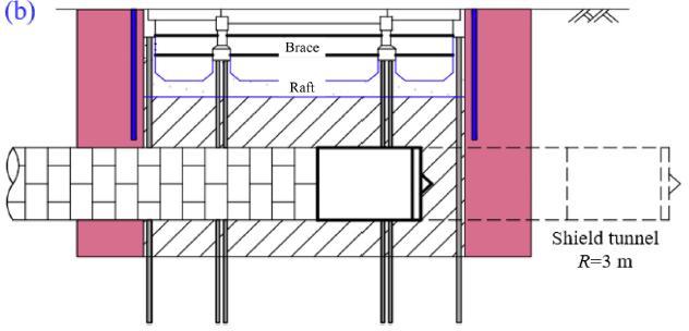
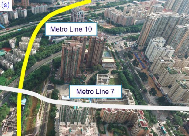
Currently, subway networks are being constructed in all prosperous cities in China. Generally, the greatest challenge encounteredincommonengineeringpracticesisthat thenewtunnelhastocrossthroughthepilefoundationsofexisting undergroundstructures(.Undersuchcircumstances,pileunderpinningtechnologyorthecuttingpilemethodmaybeadopted toremoveobstructedpiles,whichposesgreatdifficultytoengineersandtechnicians.
Fig.1.Typicalsubwaytunnelconstructioncrossingapilegroupinacomplexurbanenvironment
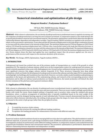
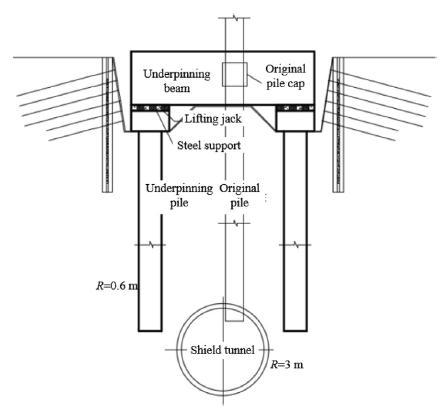
Moreover,theconstructionsiteisanunfavourableseismicsection,andtheloadsufferedbythebridgepilefoundationisvery large.Hence,theactiveunderpinningmethodneedstobeadoptedtopreventpierdeformationresultingfromthesettlementof newunderpinningpilestoensurethesafetyofthebridgepanelandtheoriginalpileduringtheconstructionandoperation stages.
Fig.2.PilefoundationunderpinningschemeofShenzhenMetroLine10passingthroughthebridgepilefoundationgroup ofGuangzhou–Shenzhenhighway
Consideringthestressconversionmechanismofthepilefoundationunderpinningprocess,thekeystepistotransfertheload oftheoriginalpilefoundationtothenewunderpinningpilethroughtheunderpinningbeaminordertoreplacetheoriginalpile
International Research Journal of Engineering and Technology (IRJET) e-ISSN: 2395-0056
foundation with the new underpinning pile. Fig. And show the maximum principal stress variation of a typical nonunderpinningpileandatypicalunderpinningpile,respectively,beforeandafterthepilefoundationunderpinningprocess.
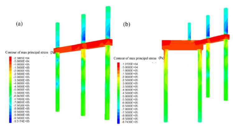
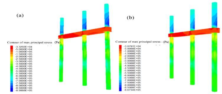
Fig.3.Stressvariationinatypicalnon-underpinnedpileduringpilefoundationunderpinning:(a)beforeunderpinningof pileR25,and(b)afterunderpinningofpileR25[24].
Fig.4.Stressvariationinatypicalunderpinnedpileduringpilefoundationunderpinning:(a)beforeunderpinningofpile R24,and(b)afterunderpinningofpileR24[24].
However, currently, research on pile foundation underpinning technology focuses on the design and optimization of the underpinning scheme, and studies on the corresponding force transfer mechanism and its influence on subway tunnel constructionarelimited.
Yuetal.[25]focusesonthereshapingprocessofrubble-pileasteroidsdrivenbymeteoriteimpacts.Amesoscaleclusterofsolid spheresisemployedastheprincipalmodelforarubble-pileasteroid,forwhichlittleisactuallyknownabouttheirinterior structureTheEigendecompositionrevealsaconnectionbetweenthecluster'sreactionsandthetypesofexternaldisturbance.
Poulos [26] presented some results of an analysisof piles near slopes in clayey soils. Schmidt [27] performed a series of laboratorymodeltestswithrigidmodelpilestostudythebehaviourofpilesinstalledatthecrestsoffourdifferentsandy slopes.Itwasfoundthatthehorizontalultimatecapacityofverticalpiledecreaseastheslopebecamesteeper.Bouafia& Bouguerra[28]andMezazigh&Levacher[29]performedcentrifugeteststostudytheresponsesofpilesin/nearaslopeunder lateralloads.
Chen&Martin[30]conductedextensiveFiniteElementanalysesofpileslocatednearslopecreststoevaluatetheeffectsof slopeandpileproximitytoslopecrestonthelateralresistanceandp-ycurvesofthesoil-pilesystem.Theirresultsshowthat forslopeangleslessthan45ºtheeffectofslopeonultimateloadcapacitybecomeslessthan10%fordistancesgreaterthan6 pilediameters,andthereforetheslopeeffectbeyondthatcanbeneglected.
Volume: 09 Issue: 08 | Aug 2022 www.irjet.net p-ISSN: 2395-0072 © 2022, IRJET | Impact Factor value: 7.529 | ISO 9001:2008 Certified Journal | Page1386
International Research Journal of Engineering and Technology (IRJET) e-ISSN: 2395-0056
Volume: 09 Issue: 08 | Aug 2022 www.irjet.net p-ISSN: 2395-0072
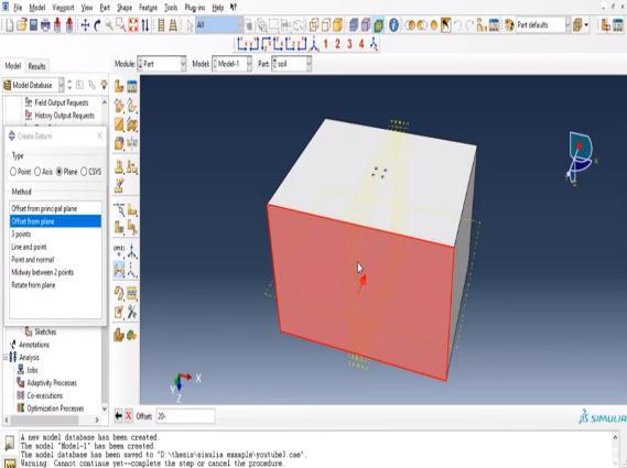
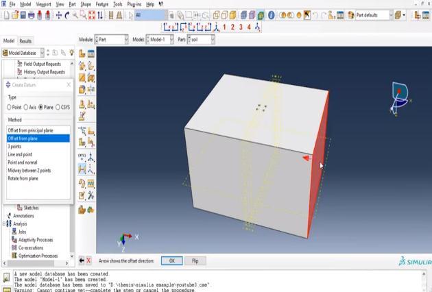
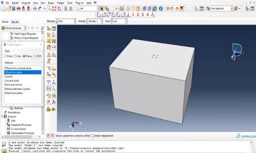
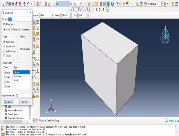
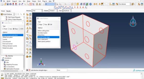
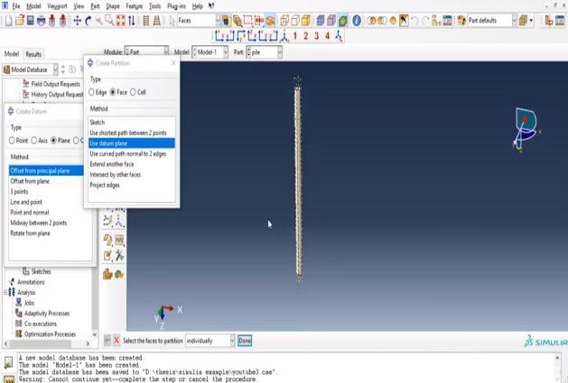
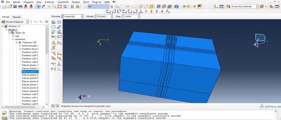
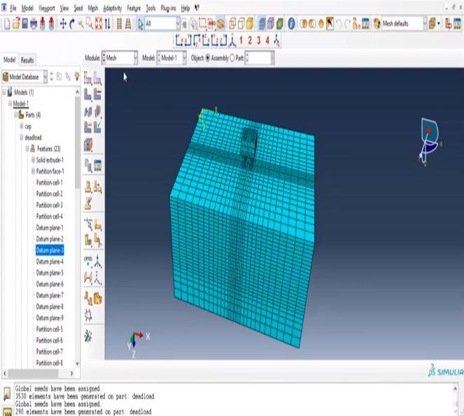
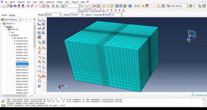
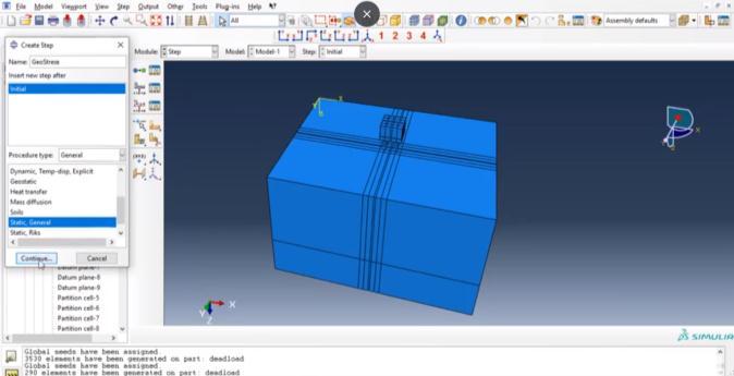
Itisbeenobtainedthatthepilefoundationwillbemodelledwiththeinvolvementofvariousstepsintothematterofdesignof specificrelevanceofthepiles.Forthedevelopmentofthepilesfoundationthefirststeptobemodelledisthemodellingofsoil which forms the environment/.surrounding around which the pile and the foundation will be laid. In the first the soil is basicallybeingmodelledintheformofcubicalstructurewhichformsthesurroundingsofthestructure.Fig showsthedesign ofsoilofthestructuretobedeveloped.
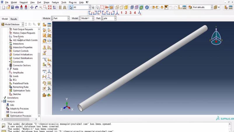
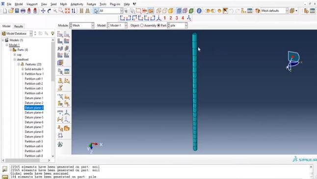
Fig5.DesignofSoil Fig6.Designofpile
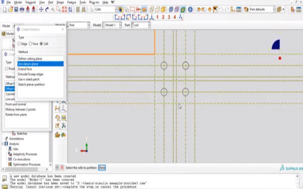
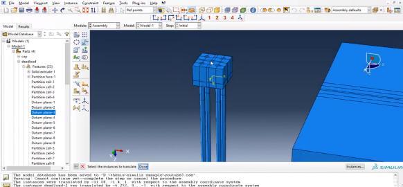
Furthermore,afterthedesignofsoilthenextstepisdesignofpiles.Thepilesaredesignedwithrespecttothecylindricalshape objectswhichfurtherwillbedwelledwiththesoil.Pilesofvaryingdiameterswereusedforthedesignofcombinationofpiles andfoundation.Therewasavariationinthelengthaswellasdiameterinthedesignofpilesalsowithrespecttothatofthesoil.
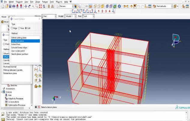
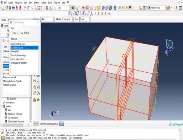
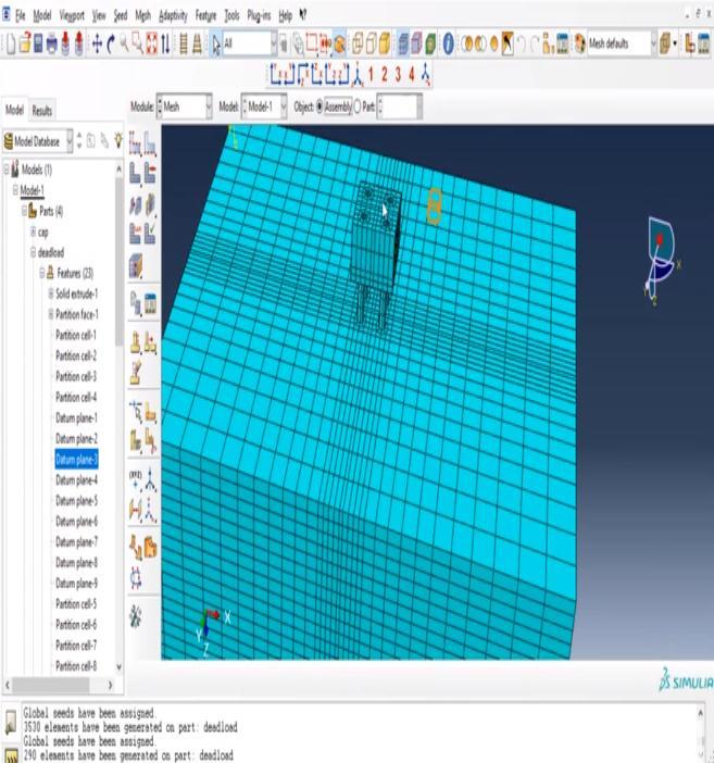
Fig.7Differentsizesofsoilforembeddingpiles
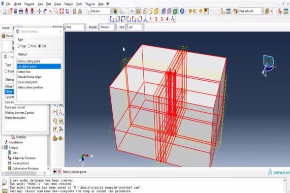
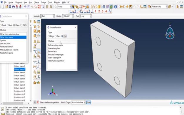
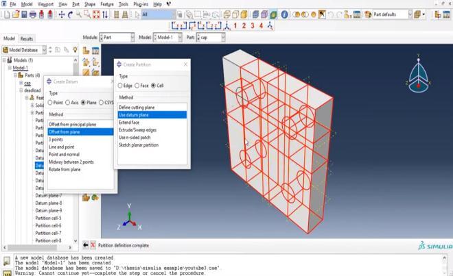
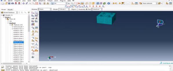
(a) Divisionfordevelopmentofcap
International Research Journal of Engineering and Technology (IRJET) e-ISSN: 2395-0056 Volume: 09 Issue: 08
International Research Journal of Engineering and Technology (IRJET) e-ISSN: 2395-0056
Volume: 09 Issue: 08 | Aug 2022 www.irjet.net p-ISSN: 2395-0072
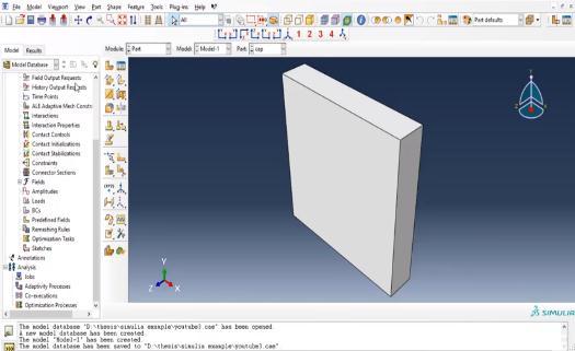
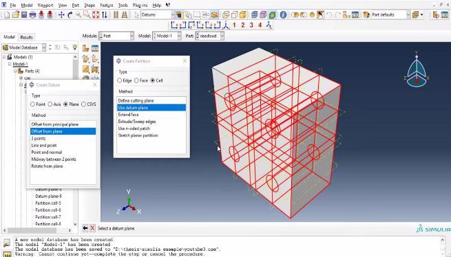
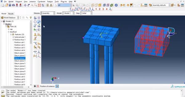
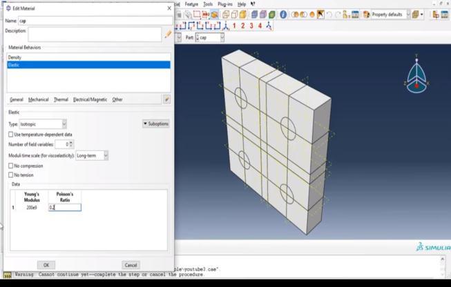
Further to development of the piles different caps with pile shaped and sized cavity holes were formed. Specifically two different pile cavity shaped caps were modelled which could be placed above and below the pile in respect to the soil. Furthermorethematerialisspecificallyassignedtodifferentmodelsnamelysoil,pilesandcapsrespectively.Eachmaterial propertyassignedisdifferentfromtheotheroneandthevaluesobtainedweredemonstratedaspertheresearchpapers.
International Research Journal of Engineering and Technology (IRJET) e-ISSN: 2395-0056
Volume: 09 Issue: 08 | Aug 2022 www.irjet.net p-ISSN: 2395-0072
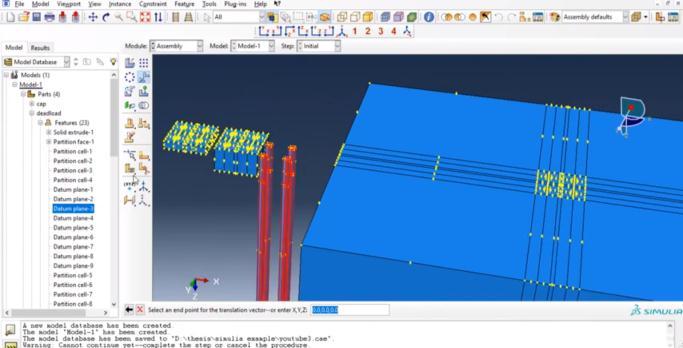
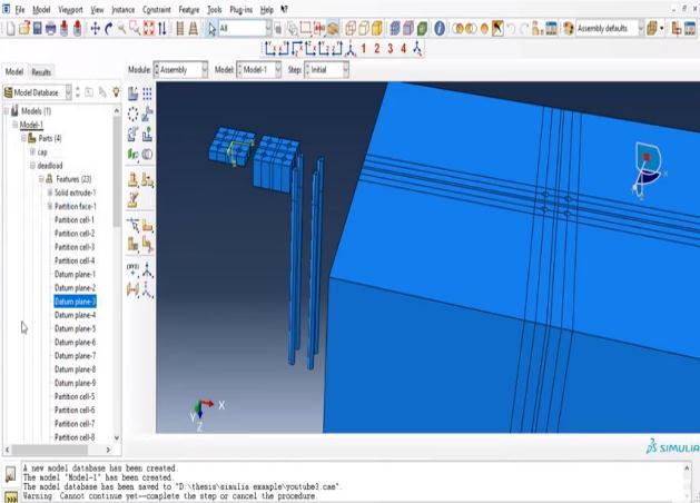
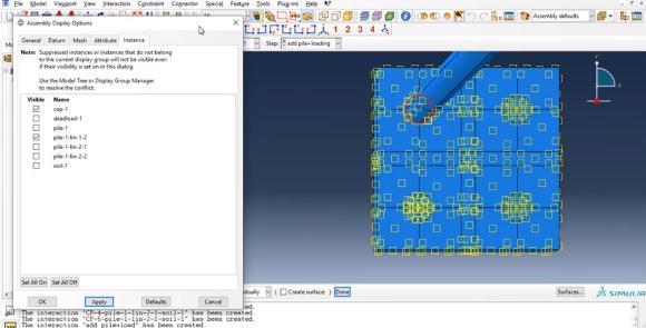
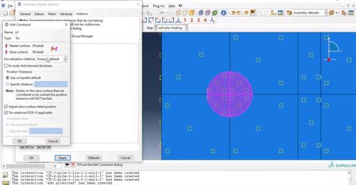
Furthermore, after assignment of materials and section to each elements like pile, soil, caps etc. separately they will be attached/assembledtogetherwithdifferenttechniques,inordertodevelopthefullmodelofpiledesign.
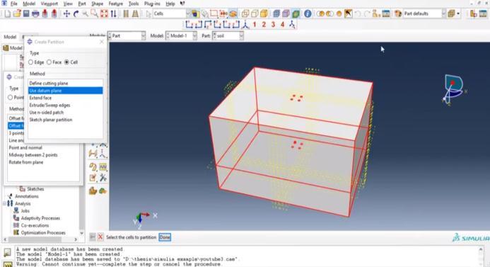
ForthedevelopmentofFEMmodelofpilesfoundationanalysis,thenextprocesstobedoneistomesh/discretizethewhole structures.Thedivisionsperformedatthetimeofmodellingofsoil,capswillbeusefulfordistinctionofdifferentmeshsizesas pertherequirementoffailuremodesandanalysisofthestructure.
International Research Journal of Engineering and Technology (IRJET) e-ISSN: 2395-0056
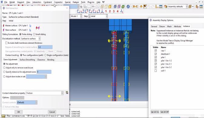
Fig14Contactdefinitionforpiledesign
Fig15Contactdefinitionforpiledesign
Everyindustrial process/productoptimization begins withTaguchi'soptimization concept.However,duetoitsfailureto resolvemulti-objectiveoptimizationproblems,thisideologyisunderfireeverywhere.Tocombatthis,literatureemphasizes theuseoftheTaguchitechniqueincombinationwiththedesirefunctionapproach,TOPSIS,fuzzyinferencesystem(FIS), principalcomponentanalysis(PCA),andGreyrelationalanalysis.Thebasicgoalistoreduceanumberofobjectivestoasingle, equivalentobjectivefunctionthatcanthenbeoptimizedusingtheTaguchimethod.Thesemethods,however,arepredicatedon somepresumptions.
A loss function exists that describes the deviation from the target (desired level) and is then converted to the S/N. The convertedS/Nratioislikewisedescribedasniceassessmentindex.Theleastversionandthegreatestlayoutareacquiredvia wayofmeansofreadingS/N ratio.The betterthe S/N ratio,the extra solidthepotential nice.Itadditionallyreducesthe sensitivityofthegadgetoverallperformancetosupplyofversion.
Table1Identifyingcontrolfactorsandtheirlevels Item
TherearethreeS/Nratiosofcommoninterestforoptimizationofstaticproblems:
Nominal-the-best/target-the-best
Inthisapproach,theclosertothetargetvalue,thebetterandthedeviationisquadratic
Theformulaforthesecharacteristicsis;
Volume: 09 Issue: 08 | Aug 2022 www.irjet.net p-ISSN: 2395-0072 © 2022, IRJET | Impact Factor value: 7.529 | ISO 9001:2008 Certified Journal |
International Research Journal of Engineering and Technology (IRJET) e-ISSN: 2395-0056
Volume: 09 Issue: 08 | Aug 2022 www.irjet.net p-ISSN: 2395-0072
Lower-is-better (LB)
Thelowerisbetterapproachheldwhenacompanydesiressmallervalues.Theformulaforthesecharacteristicsis;
Higher-is-better (HB)
Itisrequiredwhenamanufacturerdesireshighervaluesofacharacteristic.Theformulaforthesecharacteristicsis;
Here, istheaverageofobservedvalues; isthevarianceof ;and isthenumberofobservations. However,Taguchiapproachistakenintoconsiderationsimplestforsingle-goaloptimizationproblems.Itcan'tbeappliedfor buyingtheunmarriedmostexcellentplacingofsystemparametersthinkingaboutmultipleoverallperformanceparameter. Taguchi’sexperimentaltechniquehasbeenaccompaniedtolimitthetesttrails,andL16orthogonalarrayhasbeenusedto carryouttheexperimentalruns.Besides,ANOVAhasbeenaccomplishedtodiscovertheimportanceofsystemvariables.Blast Load,BondingStrengthandThicknessaretakenasenterparametersandmostdisplacementasaOutputparameters.
TaguchiArray L16(4^3) Factors: 3 Runs: 16
Table2DesignofexperimentL16orthogonalarray
Sr. No Theoretical Load (N) Applied Load (N/mm2) Total settlement (mm) 1 195 212 1.298 2 195 1018 1.314 3 195 1781 1.396 4 195 2460 1.389 5 980 212 2.125 6 980 1018 2.198 7 980 1781 2.179 8 980 2460 2.199 9 1764 212 2.919 10 1764 1018 2.979 11 1764 1781 3.011 12 1764 2460 3.121 13 2452 212 3.987 14 2452 1018 3.978 15 2452 1781 3.790 16 2452 2460 3.980
2022, IRJET | Impact Factor value: 7.529 | ISO 9001:2008 Certified
International Research Journal of Engineering and Technology (IRJET) e-ISSN: 2395-0056
Volume: 09 Issue: 08 | Aug 2022 www.irjet.net p-ISSN: 2395-0072
Response Table for Signal to Noise Ratios
Largerisbetter
Response Table for Means
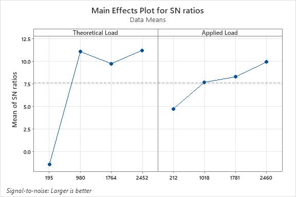
Table3SignaltoNoiseratios
Level Theoretical Load Applied Load 1 -1.434 4.710 2 11.033 7.644 3 9.709 8.247 4 11.183 9.888 Delta 12.617 5.178 Rank 1 2
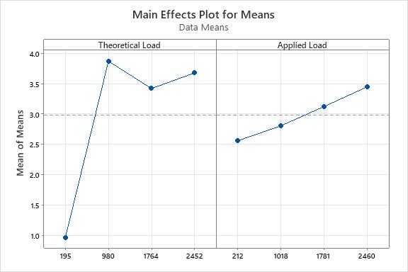
Table4Means
Level Theoretical Load Applied Load 1 0.9721 2.5604 2 3.8712 2.8074 3 3.4209 3.1248 4 3.6775 3.4492 Delta 2.8991 0.8889 Rank 1 2
The Level 2 of A and level 4 for B gives the maximum settlement which shows in Fig. Interestingly A2B4 is the best combinationformaximumsettlement.Itcanbeseenthattheoreticalloadof980Nandappliedload2460Nandgivesthe optimumresultformaximumsettlementof3.980mm.
Fig.16Maineffectplotformeans
2022, IRJET | Impact Factor value: 7.529 | ISO 9001:2008 Certified Journal |
International Research Journal of Engineering and Technology (IRJET) e-ISSN: 2395-0056
Volume: 09 Issue: 08 | Aug 2022 www.irjet.net p-ISSN: 2395-0072
Fig.17MaineffectplotforSNratios
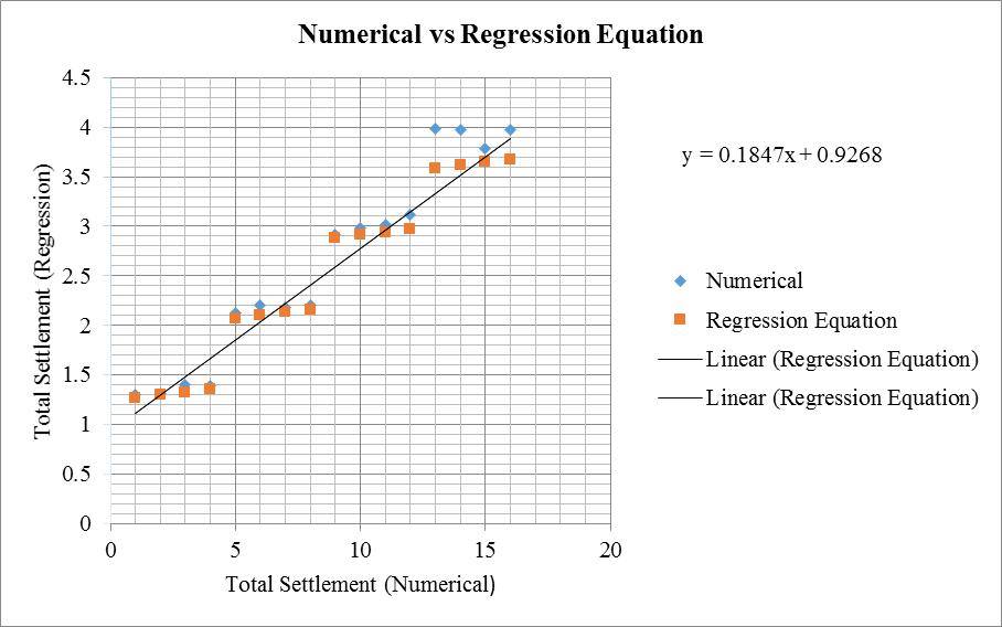
Inregressionmodel,theoreticalloadandappliedloadareindependentvariableandmaximumsettlementisadependent variable.
Inthismodel,therelationshipbetweentheoreticalloads,appliedloadandmaximumsettlementwereanalysed.
Totalsettlement=1.056+0.001029TheoreticalLoad+0.000396AppliedLoad
Table-5MaximumDisplacementNumericalvsRegressionequation
TotalSettlement Numerical RegressionEquation 1 1.298 1.265 2 1.314 1.296 3 1.396 1.327 4 1.389 1.354 5 2.125 2.072 6 2.198 2.104 7 2.179 2.134 8 2.199 2.161 9 2.919 2.879 10 2.979 2.911 11 3.011 2.941 12 3.121 2.968 13 3.987 3.587 14 3.978 3.619 15 3.790 3.649 16 3.980 3.676
S.No
2022, IRJET | Impact Factor value: 7.529 | ISO 9001:2008 Certified Journal |
International Research Journal of Engineering and Technology (IRJET) e-ISSN: 2395-0056
Volume: 09 Issue: 08 | Aug 2022 www.irjet.net p-ISSN: 2395-0072
Byadjustingthetheoreticalloadandappliedload,thegoaloftheanalysisofvarianceistoidentifythekeyvariablesthat significantlyinfluencethemaximumsettlement.Thelevelofsignificanceofthefactors andhowtheparametersaffectthe answerarebothclearlyshownbyANOVAanalysis.Blastload,bondingstrength,andthicknessarethethreeprimaryfactors takenintoaccountinthisstudy.TheR2value(34.37percent)formaximumdisplacementisclearly shownbytheANOVA analysis.AhighR2valueshowsthatthetheoreticalandnumericalmodelsaremorecompatible.Here,thetheoreticalload's 0.030Pvalueisimportant.ThemainoutputofANOVAanalysisonvariancearrangedinTables6and7.LargerFvalue(5.94) indicatesthatthevariationoftheprocessparametermakeasignificantchangesonmaximumsettlement.
Table-6ANOVAformaximumsettlement
Source DF Adj SS Adj MS F-Value P-Value Regression 2 13.878 6.939 3.40 0.065
TheoreticalLoad 1 12.107 12.107 5.94 0.030 AppliedLoad 1 1.771 1.771 0.87 0.368
Error 13 26.495 2.038
Total 15 40.373
Table–7Coefficientformaximumdisplacement
Term Coef SE Coef T-Value P-Value VIF
Constant 1.056 0.888 1.19 0.256
TheoreticalLoad 0.001029 0.000422 2.44 0.030 1.00 AppliedLoad 0.000396 0.000425 0.93 0.368 1.00
2022, IRJET | Impact Factor value: 7.529 | ISO 9001:2008 Certified Journal
International Research Journal of Engineering and Technology (IRJET) e-ISSN: 2395-0056
Table8ModelSummary
S R-sq R-sq(adj) R-sq(pred) 1.42761 34.37% 24.28% 6.41%
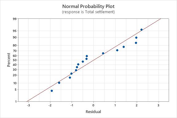
Paretochartshowsindicatethetheoreticalloadplaysasignificantroleforthemaximumsettlementfollowedbyappliedload. Figrepresentthenormalprobabilityplotformaximumsettlement.Itshowsthedataarefollowingnormaldistributioncurve, whichfitsthemodelsuitableforpredictionofmaximumdisplacementvalues.InFig.wecanseeonlyonevalueasaoutlier,soit provethefeasibilityofnumericalanalysis.
Fig.19Paretochart
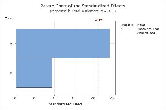
Fig.20NormalProbabilityPlot
Volume: 09 Issue: 08 | Aug 2022 www.irjet.net p-ISSN: 2395-0072 © 2022, IRJET | Impact Factor value: 7.529 | ISO 9001:2008 Certified Journal |
International Research Journal of Engineering and Technology (IRJET) e-ISSN: 2395-0056
Volume: 09 Issue: 08 | Aug 2022 www.irjet.net p-ISSN: 2395-0072
Prediction
S/N Ratio Mean 13.2986 4.33506
Sizeofthepilesdevelopedwerevaryingfrom100mmto1000mmwithdifferentheightrangesvaryingfrom500mmto 2000mminordertoanalysetheperformanceofthestructurewithrespecttogeometricalparameters.
Sizeofpilesweresubjectedtodifferentintensityofstaticloadsvaryingfrom195Nto2095N,inordertoattainthe variationorperformanceofthestructurewithrespecttothevaryingload.
Magnitudeofdisplacementinpilesofsmallersizeislowerwithsamethicknessonactionofsameintensityblastloads.
Magnitudeofstressesinpilesofsmallersizeislowerwithsamethicknessonactionofsameintensityblastloads
Intensityofdisplacementineachpiledesigncombinationshowedanincreasewiththeenhancementintheintensityof blast loads. The maximum displacement of 3.98 mm happens at 2495 N load while at 195 N load the maximum displacementwas1.238mm.
Intensityofstressesineachpiledesigncombinationshowedanincreasewiththeenhancementintheintensityofblast loads.Themaximumdisplacementof3.98mmhappensat2495Nloadwith2460N/mm2whileat195Nloadwith212 N/mm2 themaximumdisplacementwas1.238mm.
ANOVAanalysisisalsocarriedtoanalysetheparametricperformanceofPiledesign.
Taguchianalysisisperformedforanalysisoftheparametersofpiledesign
Paretoanalysisshowstheblastloadappliedhasmoresignificantimpactthanthepressureappliedovertheareain performanceofthestructurewithrespecttothemaximumdeviationofthestructure.
1. Luan,X.,Cheng,L.,Song,Y.,&Zhao,J.(2020).Betterunderstandingthechoiceoftravelmodebyurbanresidents:New insightsfromthecatchmentareasofrailtransitstations.Sustainablecitiesandsociety,53,101968.
2. Su,Z.,&Li,X.(2020).Sub-systemenergymodelbasedonactualoperationdataforsubwaystations.SustainableCities andSociety,52,101835.
3. Wang, Z. Z., & Chen, C. (2017). Fuzzy comprehensive Bayesian network-based safety risk assessment for metro constructionprojects.TunnellingandUndergroundSpaceTechnology,70,330-342.
4. Ding, L. Y., Yu, H. L., Li, H., Zhou, C., Wu, X. G., & Yu, M. H. (2012). Safety risk identification system for metro constructiononthebasisofconstructiondrawings.Automationinconstruction,27,120-137.
5. Guo, X., Wang, Z., Geng, P., Chen, C., & Zhang, J. (2021). Ground surface settlement response to subway station constructionactivitiesusingpile–beam–archmethod.TunnellingandUndergroundSpaceTechnology,108,103729.
6. Li, Z., Chen, Z., Wang, L., Zeng, Z., & Gu, D. (2021). Numerical simulation and analysis of the pile underpinning technologyusedinshieldtunnelcrossingsonbridgepilefoundations.UndergroundSpace,6(4),396-408.
7. Guner,S.,&Chiluwal,S.(2021).Cyclicloadbehaviorofhelicalpile-to-pilecapconnectionssubjectedtoupliftloads. EngineeringStructures,243,112667.
2022, IRJET | Impact Factor value: 7.529 | ISO 9001:2008 Certified Journal |
International Research Journal of Engineering and Technology (IRJET) e-ISSN: 2395-0056 Volume: 09 Issue: 08 | Aug 2022 www.irjet.net p-ISSN: 2395-0072
8. Lu,M.M.,Xie,K.H.,Wang,S.Y.,&Li,C.X.(2013).Analyticalsolutionfortheconsolidationofacompositefoundation reinforcedbyanimperviouscolumnwithanarbitrarystressincrement.InternationalJournalofGeomechanics,13(1), 33-40.
9. Kim,H.J.,Mission,J.L.,Park,T.W.,&Dinoy,P.R.(2018).Analysisofnegativeskin-frictiononsinglepilesbyonedimensionalconsolidationmodeltest.InternationalJournalofCivilEngineering,16(10),1445-1461.
10. Li,B.,Yu,J.,Zhou,Y.,Cai,Y.,Liu,S.,&Tu,B.(2021).Acomputationmodelforpile-soilstressratioofgeosyntheticreinforced pile-supported embankments based on soil consolidation settlement. Alexandria Engineering Journal, 60(1),39-48.
11. Zhuang,Y.,&Wang,K.(2017).Analyticalsolutionforreinforcedpiledembankmentsonelastoplasticconsolidatedsoil. InternationalJournalofGeomechanics,17(9),06017010.
12. Chen,R.P.,Zhou,W.H.,&Chen,Y.M.(2009).Influencesofsoilconsolidationandpileloadonthedevelopmentof negativeskinfrictionofapile.ComputersandGeotechnics,36(8),1265-1271.
13. Li,B.,&Wang,Z.Z.(2019).Numericalstudyontheresponseofgroundmovementstoconstructionactivitiesofa metrostationusingthepile-beam-archmethod.TunnellingandUndergroundSpaceTechnology,88,209-220.
14. Liu,X.,Liu,Y.,Yang,Z.,&He,C.(2017).Numericalanalysisonthemechanicalperformanceofsupportingstructures andgroundsettlementcharacteristicsinconstructionprocessofsubwaystationbuiltbyPile-Beam-Archmethod. KSCEJournalofCivilEngineering,21(5),1690-1705.
15. Thongmunee,S.,Matsumoto,T.,Kobayashi,S.I.,Kitiyodom,P.,&Kurosawa,K.(2011).Experimentalandnumerical studiesonpush-uploadtestsforsandplugsinasteelpipepile.Soilsandfoundations,51(5),959-974.
16. Khoubani, A., & Evans, T. M. (2018). An efficient flexible membrane boundary condition for DEM simulation of axisymmetricelementtests.InternationalJournalforNumericalandAnalyticalMethodsinGeomechanics,42(4),694715.
17. Shire, T., Hanley, K. J., & Stratford, K. (2020). DEM simulations of polydisperse media: efficient contact detection appliedtoinvestigatethequasi-staticlimit.ComputationalParticleMechanics,1-11.
18. Sloan, S. W., & Randolph, M. F. (1982). Numerical prediction of collapse loads using finite element methods. InternationalJournalforNumericalandAnalyticalMethodsinGeomechanics,6(1),47-76.