1
International Research Journal of Engineering and Technology (IRJET) e-ISSN: 2395-0056

Volume: 09 Issue: 08 | Aug 2022 www.irjet.net p-ISSN: 2395-0072
1
International Research Journal of Engineering and Technology (IRJET) e-ISSN: 2395-0056
Volume: 09 Issue: 08 | Aug 2022 www.irjet.net p-ISSN: 2395-0072
Abstract - Structural analysis of dental chair is an important aspect while studying patient’s dental anatomy. It’s a specially designed and equipped medical instrument which supporting a movement of patient andthe instruments applied during the treatment. It’s usually reclines and positions the patients whole body by driving pedestal mechanism. These mechanism sometimes provides axial as well as linear motion and are attached to a Dental Engine. This engine is a companion device that provides power, suction, andwater also considering patients comfort during treatment.
Dental chair are very useful assets inexamining, extracting and doing surgeries driving with pedestal mechanism and utilizing hydraulic power ensuring smooth and quiet adjustment of all moving parts. Patients comfort are provided using headrest, backrest system with stylish, fully adjustable and comfortable cushions. To this end, dental chairs can contain a bewildering array of attachments, either on the chair itself or on the ubiquitous Dental Engine:spittoon bowls, suction tubes, pneumatic tubes to power various parts of the equipment used in cleaning and surgeries, etc.
Recent changes in dental chairs consist of metal andplastic bodies and also provides hygiene and ease to clean facilities to avoid any bacterial infusion to minimize the risk of infection. Particular sitting arrangement with leg rest folded away makes dentist and patients interact more comfortably during face-to-face consultation and treatment. Dental chairs also provides vertical and horizontal adjustment have the ability to adjust the height of the chair according to the operating requirements of the dentist or the patient. The current study focuses on the structural analysis and optimization of the lifting design of the dental chair according to the weight load and medical requirements to adjust the scissor link length for a stronger, safer and optimized design.
Words: Dental Chair, Dental Engine, recliner, articulated,FEA
Oral health is an essential part of the general health care. TherearemanyoralhealthissuesthatconcernIndiadespite havingthemaximumnumberofdentalschoolsintheworld. Indialacksbasicdatatoknowtheexactprevalenceoforal diseases, which is the first requirement for setting any national policy or manpower allocation. India is a vast country,nationswithinnations,withgreatdiversityindiet and behavior [1]. Reaching the dental care services to the
lowerandmiddleclasspeopleisreallyachallengingtaskas thereisstilllackofawarenessamongthesepeoples.Evenif sometimesitreachestothesepeoplemanyofthesedental carecentresarenothavingsufficientworkingfacilitiesand services. Dental units are devices which are useful in examining and caring of teeth and mouth (like drilling, filling, cleaning and examination) [2]. Dental chair is an integral part of dental unit providing functionalities like patientslegand back inclinationaswell asriseand fall of chairanditcanalsohaveabilitytomoveupanddownusing motorandhydraulicmechanisms[3].
This paper will be defined as optimization of dental chair structureaspertheanthropologyandmedicalrequirement to adjust the scissor link length for stronger, safer and optimizeddesign.
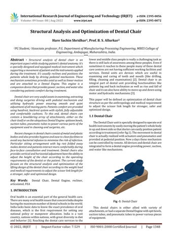
TheDentalChairunitisspeciallydesignedtooperateoral healthinstrumentsbyeasilymovingthepatient’swholebody inupanddownsidesothatdoctorcaneasilypositionpatient accordingtotreatment(referfig.1).Themovementtodental chairisactuallyrealizedwithactuatorsandpneumaticsand providedatpedestalposition.Nowadaysthesemechanism canbecontrolledbyremote.Alldevicesanddentalchairare integratedtoformadentalengineprovidingpower,suction, andwaterlikemechanisms.
This dental chairs is either allied with variety of attachments,orhadaseparateDentalEnginewithspitbowls, suctiontubes,andpneumatictubestopowervariouspieces ofequipment.
International Research Journal of Engineering and Technology (IRJET) e-ISSN: 2395-0056
Volume: 09 Issue: 08 | Aug 2022 www.irjet.net p-ISSN: 2395-0072
Thispapergivesanideaaboutactualworkdoneonlinear static analysis of Dental chair system and optimization of scissor link lengths. We have provided respected CAD modelsanddesignsofexperiment.
S. P. Chaphalkar, S. N. Khetre, A. M. Meshram had explained the modal analysis. This paper presents some basicconceptsofmodalanalysisoftransversevibrationof fixed free beam which is specially designed to absorb the shocks. It is described an experimental apparatus and the associated theory which allows to obtain the natural frequenciesandmodesofvibrationofacantileverbeam.The concept of modal analysis plays an important role in the design of practical mechanical system. So, it becomes important to study its effects on mechanical system for different frequency domain i.e. low, medium and high frequency[4].
Agashi,Andre&Daywin,Frans&Gozali,Lina&Adianto, & Purna Irawan, Agustinus had proactively studied and presentedadesignofswivelchairforbendingmachinework station which will help the workers to easily do their cumbersomeworksandincreasetheirproductivityprocess. Due to long duration of standing work workers may experience some physical fatigues, the research is mainly focusedtocalculateandtoreducethisfatiguewiththehelp ofswivelchairbyconsideringtheNordicBodyMap[5].
FBham,HPerrie,JScribanteandC-ALeehavedoneaudit on how paediatric dental chair sedation is useful in the current practice of dentist in South Africa. They have presenteda reportwhichshowsa prospective,contextual anddescriptivestudydesignwithrandomlyselecteddental practitioners[6].
A. Bijalwan and A. Misra represented and compared traditionalwithwearablechairswhichareusedatcompact work places.Theyhavemainlyfocusedonthemechanical designandfiniteelementanalysis(FEA)ofthemechanism whicharesatisfyingequilibriumandstabilitycriterionand whicharecapableofreducingthephysicalfatigueamongthe workersinassemblylineandfactories[7].
Fromliteraturereview,DesignOptimization&Analysis of a Dental Chair for Linear Static Structural Analysis is extremelyimportantforanalysingweightandsizeofvarious components,designershavetochangethedifferentsizesof scissorlengthofDentalchairstructure,thismayleadtoover designorunderdesign.
As discussed above we have deliberated the need of structuraloptimizationofdentalchairliftingmechanismas
perthecustomerrequirements,herewewouldliketodesign theliftingsystemandbasedontheweightandlengthofthe scissorlink,wewouldliketoanalyzetheframeforcorrect sizingofcomponentbyconsideringthedefinedconstrained.
We also like to compare the weight, deflection, factor of safetyfortraditionalandnewdesignoptimizevertically.
Partial differential equations are used to define complex physicalphenomenaintheformofnumericaltechniquesin Finite Element Analysis (FEA) (also called Finite Element Method (FEM)). This method is widely used in many problem solving areas like, structural analysis, mass transport,fluidflowandelectromagneticpotential.
WecanusetheFEMmodeltopredictandfindthebehavior ofsystemstateorresponse toexternal loadsaccordingto the design variables applied under their operating conditions.Designstudyisasimulationofmechanicaland thermal systems, to reduce the design cycle time, and to improveoverallsystemperformancefordifferentscenarios.
StepstofollowinFEAprocessareasbelow:
Geometric representation creates the geometry of the problembydefiningfeaturesofthesystemandconsidering different design variables and various environmental conditions. These are then analyzed and stored in a CAD databasetocreatesomeusefulgraphics.
Element formulation thisstepdevelopstheequationsthat describethebehaviorofeachfiniteelementbyusingsome mathematical numerical techniques by discretizing them intosmallelements.Thematerialpropertiesofeachelement are taken into account when formulating the governing elementformulationequations.Thisinvolvesobtainingaset ofalgebraicequationstosolvedisplacementfunctionwithin eachelement.
Assembly Getsasetofglobalequationsfortheentiremodel from the individual element equations. The loads and support (boundary) conditions are applied to the appropriatenodesofthefiniteelementmesh.Thisassembly isdonebyinterconnectingmanysmallerbodiesorunitsalso calledfiniteelementsatcommonpoints.
Solutionofequationsprovidescomputationoftheunknown valuesoftheprimaryfieldvariablesandthesolutionforthe unknown nodal degrees of freedom (or generalized displacements). These solutions are used then to evaluate additional,derivedvariableslikeelementstresses,heatflow andreactionforces.
We need a higher accuracy requirements by a lot more complexproblemdata.AFEAmodeliscomposedofseveral different components that together describe the physical
International Research Journal of Engineering and Technology (IRJET) e-ISSN: 2395-0056
Volume: 09 Issue: 08 | Aug 2022 www.irjet.net p-ISSN: 2395-0072
problemtobeanalysedandtheresultstobeobtained.The computational model designed for simulation using FEA includesvariousfactorslikeelementproperties,discretized geometries, dynamics, general loads and boundary conditions, material properties, analysis type, and output requirements.
Discretisedgeometryismadeupofsmallintegratedfinite bodiesorelements.Theseelementsandnodesdescribesthe basicgeometryofthephysicalstructurebeingsimulatedor modelled.
These finite elements are interconnected at some commonpointstoformthephysicalstructureofthedesign whicharediscreteinnatureandwhichinturnsharesome common properties and behaviour. Node coordinates and elementconnectivity thatis,whichnodesbelongtowhich elements makeupthegeometryofthemodel.Thesetofall elementsandnodesinamodeliscalledamesh.Ingeneral, themeshisonlyanapproximationoftheactualgeometryof thestructure.
The type of element and the total number of elements used in the mesh affects the results obtained by the simulation.
Thegreaterthemeshdensityisdirectlyproportionalto theaccuracyandtheresultsobtainedfromthesimulation. Asthemeshdensityincreases,theanalysisresultsconverge toauniquesolution,andthecomputertime.
The selection of proper element and order (e.g. linear, parabolic,andcubic)isverynecessaryintheproblemdata simulation. Thechoiceoftheelementdefinesthefunctionof displacements between the interconnected points. The validityofsimulationresultsinfeaturelibrariesislimitedby theavailabilityofaccuratematerialdata.
Complex models can be easily understood with 3D models which gives better illustration of deformation. 3D simulationmodelisthattheeachandeverypartismeshed with 3D objects. The similarity when modelling with 1D element,2Delement,and3Delementisthattheyareableto generatethesameresultparameters.3Dsolidelementsonly accountsfortranslationaldisplacements.
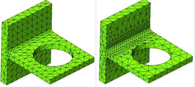
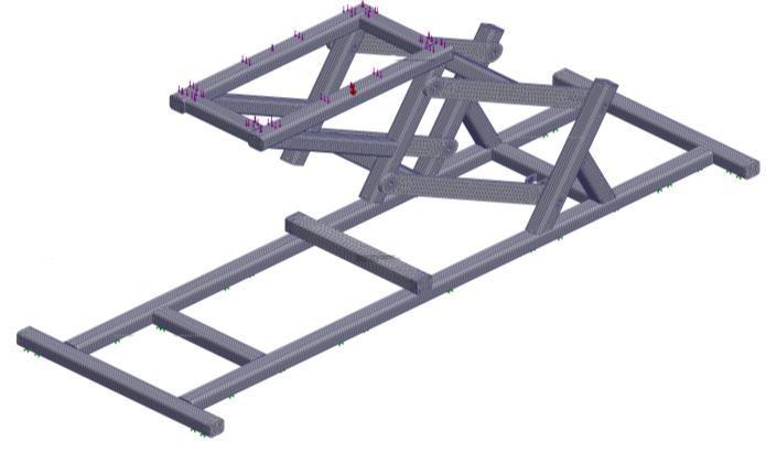
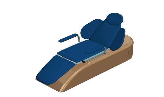
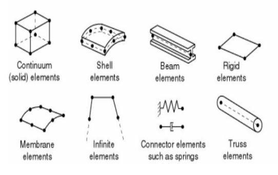
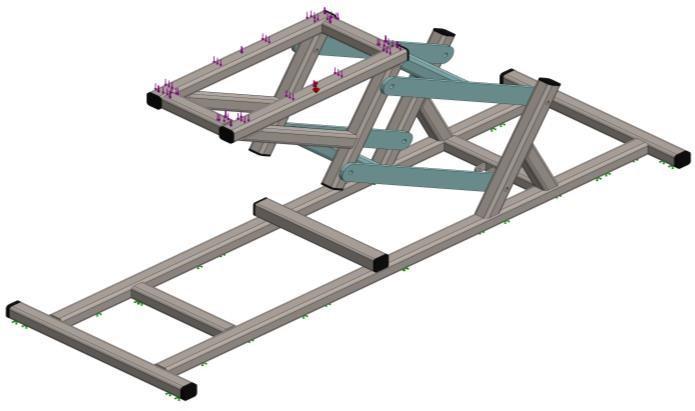
Thesimulationofindividualfiniteelementisdisplayedin fig.2andgeneratedsimulationofliftingchairbyapplying elementspropertiesandmaterialdataongivendentalchair modelisshowninfig.3.
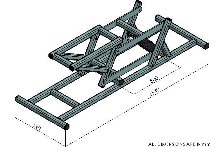
Inthispaperwehavetakensomecommonmeasurement ofdentalchairwhicharesowninfig.4.Differentcommon elementtypeisshowninfig.5
Fig -4: DimensionofLiftingMechanisminDentalChair
Materialdataisanimportantfactorwhilecreatingahigh accuracy simulation. To achieve the high accuracy for complexstructureswerequiredhighqualitymaterialdata. All materials behaves differently according to different environmentalconditionsappliedonitandpossessdifferent
International Research Journal of Engineering and Technology (IRJET) e-ISSN: 2395-0056
Volume: 09 Issue: 08 | Aug 2022 www.irjet.net p-ISSN: 2395-0072
boundary conditions to each environmental factors. Variationsandnumberofvariationsofmaterialproperties cangivemoreaccurateresultsandsimulationperformance.
the first step in any FEA method. Some of the common analysis types include linear/nonlinear static/dynamic, electrical,multiphysics,buckling,heattransfer,fatigue,and optimization.
Staticanalysisor quasi-staticanalysisisdone by applying theloadslowlyonthestructureforslowerdeformationof thebody.Wemaysaythattheinertiaforceisnegligiblein this case which leads no impacts no vibration. Dynamic analysisisnothingbuttheloadschangingperunittimeor frequency.Forexample,youperformadynamicanalysisto simulatetheeffectofanimpactloadonacomponentorthe responseofabuildingduringanearthquake.
Modal analysis is mostly used to identify the natural frequenciesintheexaminingbodystructure.Itisapowerful tool that allows engineers to design a product to avoid excitationtomatchthenaturalfrequenciesofthestructure, therebyeliminatingorminimizingexcessivevibration.
Fig -5: Commonelementfamilies
Inadditiontothemodelingmethodandtheapplicationof loadsand boundariesconditions, 1D element, 2D element and 3D element are also different in terms of structural deformation. Stress is created in physical structure by applyingloadsandthetechniqueiscontinuedgraduallybya prescribedamount(nonzerodisplacements)byconsidering theboundaryconditionswhichaffectsthephysicalstructure ofthecomplexbody.
Themostcommonformsofloadinginclude:
• Pointloads
• Distributedtractionsonsurfaces
• Pressureloadsonsurfaces
• Distributededgeloadsandmomentsonshelledges
• Thermalloads
• Bodyforces,suchastheforceofgravity
• In a static stress analysis adequate boundary conditionsmustbeusedtopreventthemodelfrom movingasa
• Rigidbodyinanydirection;otherwise,unrestrained rigid body motion causes the simulation to stop prematurely.
• The potential rigid body motions depend on the dimensionalityofthemodel.
Theperfectanalysistypeforsimulationcanbedecidedby evaluating the applied type of load on structure, the inclusionofinertialeffectsandmaterialpropertieswhichis
Anonlinearstructuralproblemisonewherethestiffnessof the structure changes as it deforms. Most of nonlinear behaviour analysis is observed in all physical structures whichhasthelargedeformationproblems.Linearanalysisis aconvenientapproximationthatisoftenadequatefordesign purposes. It is clearly inadequate for many structural simulations including manufacturing processes such as forgingorstamping;crashanalysis;andanalysesofrubber componentssuchastiresorenginemounts.
Dassault Systems SOLIDWORKS Corp. offers complete 3D software tools that let you create, simulate, publish, and manageyourdata.SOLIDWORKSproductsareeasytolearn and use and work together to help you design products better,faster,andmorecost-effectively.
The SOLIDWORKS focus on ease-of-use allows more engineers, designers and other technology professionals thaneverbeforetotakeadvantageof3Dinbringingtheir designstolife.
SOLIDWORKS Simulation Standard is an intuitive virtual testingenvironmentforstaticlinear,time-basedmotion,and high-cycle fatigue simulation. It delivers a concurrent engineeringapproach,helpingyouknowifyourproductwill performproperlyandhowlongitwillbelastingthedesign phase,SOLIDWORKSSimulationProfessionalenablesyouto
Optimize your design, determine product mechanical resistance,productdurability,topology,
Natural frequencies, and test heat transfer and buckling instabilities, it can also perform sequential multi-physics simulations.
International Research Journal of Engineering and Technology (IRJET) e-ISSN: 2395-0056
Volume: 09 Issue: 08 | Aug 2022 www.irjet.net p-ISSN: 2395-0072
Traditionaldesignofdentalchairgeometryisshowninthe following fig. 6. We can clearly see the arrangements of folding and base for flexible movement of the load being appliedonthechair.
Table -1: MeshInformation
Meshtype SolidMesh
MesherUsed: Standard mesh Automatic Transition: Off IncludeMeshAuto Loops: Off Jacobianpointsfor Highqualitymesh 16Points
ElementSize 0.005m Tolerance 0.00025m
MeshQuality High
Fig -6: GeometryDetailsStructureFrameSimplified (UpperandLowerScissorshighlightedinBluecolor)
Componentsusedinthedentalchairsimulationare: 1) BaseFrame 2) UpperScissor 3) LowerScissor 4) ChairSupport 5) Motor 6) Piston 7) Couch
3.2
Dentalchairassemblywiththescissorlengthof300mmis shown in fig. 7. Stress applied is shown with blue bars on assembly
Table -2: meshinformation–details TotalNodes 1006190
TotalElements 522719
MaximumAspect Ratio 18.27
%ofelementswith AspectRatio<3 99.2
Percentageofelements withAspectRatio>10 0.00153
Percentageofdistorted elements 0
Timetocomplete mesh(hh;mm;ss): 00:01:17
Computername: DESKTOP
The finite element properties used in this project is describedinthetable1andtable2whichinturnalsoshows themeshformationanalysiswiththetotalelements.
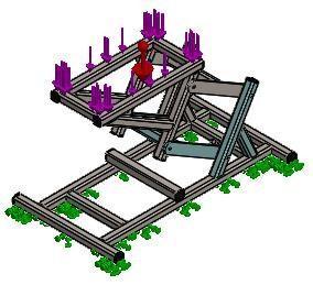
Fig -7: Dentalchairassembly:scissorlength(300mm)
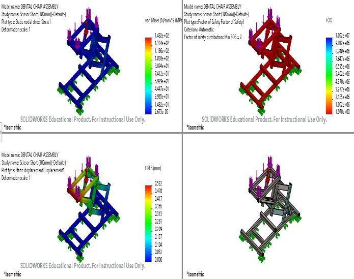
Stress analysis is an important part of the FEA which examinestheproblembodyatitsextentlevel.Thisisdone byapplying external forceonthe examiningbodyandthe
International Research Journal of Engineering and Technology (IRJET) e-ISSN: 2395-0056
Volume: 09 Issue: 08 | Aug 2022 www.irjet.net p-ISSN: 2395-0072
statisticsofappliedstressondentalisshowninTable3,4 and5.Theresultingsimulationisshowninfigure8.
Table -3: Reactionforces
Selection set Units Sum X Sum Y Sum Z Resultant
Entire Model N 0.00 0946 283
2,394 .6 8
9.0 658 7e05
2,39 4.68
Name Type Min Max Stress1 VON:von MisesStress
2.673e05N/mm^2 (MPa) Node: 172327
1.482e+02N/ mm^2(MPa) Node: 382682
Table -6: Displacementparameters
Name Type Min Max Displacement1 URES: Resultant Displacement
0.000mm Node: 9344
0.522mm Node: 707483
Fig -8: DentalChair(ScissorShort)-Stress-Stress1
Table -5:Strainappliedindentalchairproblemdata
Name Type Min Max Strain1 ESTRN: Equivalent Strain
2.688e-10 Element: 34482
4.673e-04 Element: 187995
TheDisplacementsisusedtocalculatestrainandstressin each element at the nodes surrounding the element. The displacement parameters are shown in Table 6 and respectedsimulationispresentedinfig.9and10.
Fig -9: DentalChair(ScissorShort)-DisplacementDisplacement1
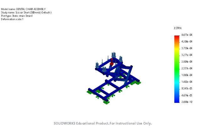
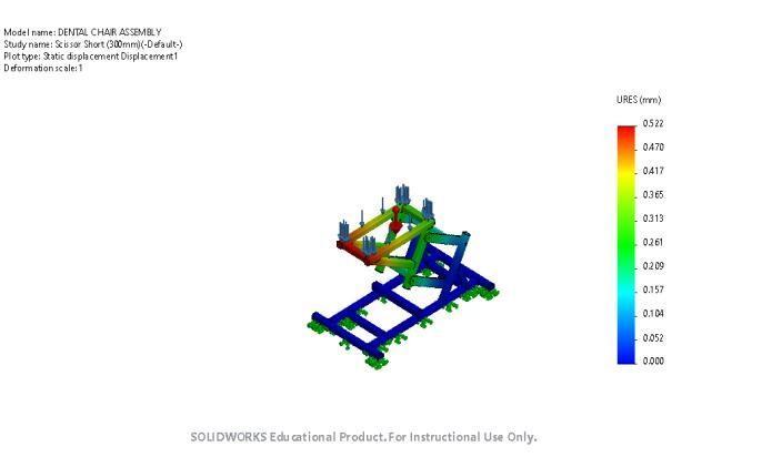
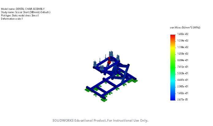
Fig-10: Dentalchair(ScissorShort)Strain-strain1
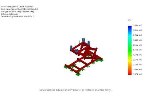
To evaluate whether the given structure is fit for the intendedpurposewehavetostudyFEanalysisresultswith comparison, this is called allowables. The ratio of (Allowable/FEAResult)iscalledFactorofSafety(FoS).FoS parameterisdefinedinTable7andsimulationisgiveninfig. 11.
Table -7: Factorofsafetyparameter
Name Type Min Max Factorof Safety1 Automatic 1970e+00 Node:382682 1092e+07 Node:172327
2022, IRJET | Impact Factor value: 7.529 | ISO 9001:2008 Certified Journal |
International Research Journal of Engineering and Technology (IRJET) e-ISSN: 2395-0056
Volume: 09 Issue: 08 | Aug 2022 www.irjet.net p-ISSN: 2395-0072
3
Fig -11: DentalChair(ScissorShort)–Factorofsafety–FactorofSafety1
Thefig.12,13and14comparesthefiniteelementanalysis withdifferentparametersofdisplacement,stressandFoSby simulation.Themodelvalidationobtainsbycomparingthe stressanalysisbyFEM.Themaximumstressvalueiscolored inredareaintheFEMsimulation.
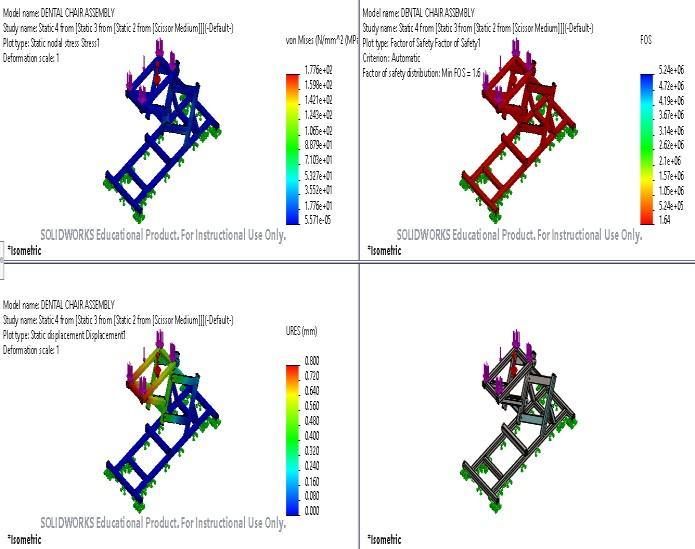
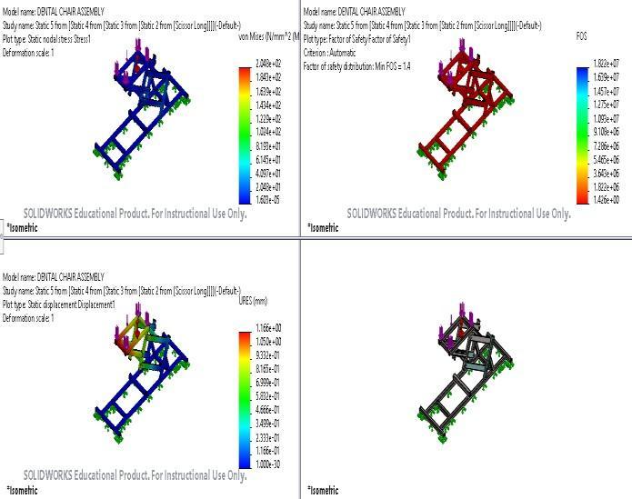
Fig -14: CompareResultforScissorLinkLength(300mm)
Thisprojectworkgivesanideaaboutstructuralstrengthof dental chair lifting structure, based on the above study, structuralanalysisresultsforCase-1:ScissorLinkLong(500 mm),Case-2:ScissorLinkMedium(400mm),andCase-3: ScissorLinkShort(300mm)wereobtainedforcomparative study,toconcludethesafeandoptimaldesign.
In Case-1: Scissor Link Long (500 mm), the obtained maximumstresswas204.8MPa,withmaximumdeflection of1.166mmandFactorofsafety1.4withassemblyweight of102.19kg.For,Case-2:ScissorLinkMedium(400mm), the obtained maximum stress was 177.6 MPa, with maximumdeflectionof0.799mmandFactorofsafety1.6 withassemblyweightof98.93kg.For,Case-3:ScissorLink Short(300mm),theobtainedmaximumstress was148.2 MPa,withmaximumdeflectionof0.522mmandFactorof safety2withassemblyweightof95.67kg.
Thecomparativestudyresultsshowthatthereis,
• 3.2%ofweightoptimizationinCase-2thanCase-1, thatisdirectlylinkedtothematerialcost.
• 17.65 % greater factor of safety in Case-2 than Case1,saferdesign.
• 6.37%ofweightoptimizationinCase-3thanCase1, thatisdirectlylinkedtothematerialcost.
• 30%greaterFactorofsafetyinCase-3thanCase-1, saferdesign.
Theoptimizeddesignforthedentalchairliftingstructureis observedinCase-3,withScissorlinklengthas300mmand achieving lowest deflection and Von. Mises stress with highestfactorofsafety.Hence,theshortscissorlengthupto 300mm gives the safe and optimal design for the Dental Chair.
International Research Journal of Engineering and Technology (IRJET) e-ISSN: 2395-0056
Volume: 09 Issue: 08 | Aug 2022 www.irjet.net p-ISSN: 2395-0072
Therefuturescopeofresearchworkmaybeasfollows: Wecanincludethemechanismtoadjusttheinclinationof headrestandfootrestpadofthedentalchair.
Furtherwecandoanalysisforlineardynamicstocheckthe real-worldscenario.
[1] BatraP,SainiP,YadavV.OralhealthconcernsinIndia.J OralBiolCraniofacRes.2020Apr-Jun;10(2):171-174.
[2] W. Zhang and S. Cui, “The research and design of orthodonticplatformframework,”in4thInternational ConferenceonMechatronics,Materials,Chemistryand ComputerEngineering(ICMMCCE2015),2015,pp.700–703,doi:10.2991/icmmcce-15.2015.141.
[3] P. W. Kang, J. H. Kim, H. Kim, and J. R. Morrison, “Improving dental service via communication during treatment,”8thInt.Conf.Serv.Syst.Serv.Manag.-Proc. ICSSSM’11, pp. 3–8, 2011, doi: 10.1109/ICSSSM.2011.5959428.
[4] S.P.Chaphalkar,Subhash.N.Khetre,ArunM.Meshram, (2015), Modal analysis of cantilever beam Structure Using Finite Element analysis and Experimental Analysis, American Journal of Engineering Research, Volume4,Issue-10,pp-178-185.
[5] Agashi,Andre&Daywin,Frans&Gozali,Lina&Adianto, &PurnaIrawan,Agustinus.(2022).THEDESIGNINGOF SWIVEL CHAIR FOR BENDING MACHINE WORK STATIONATPTGRAHAADIKARYALOGAM.
[6] BhamF,PerrieH,ScribanteJ,LeeCA.Paediatricdental chairsedation:AnauditofcurrentpracticeinGauteng, SouthAfrica.SAfrMedJ.2015Jun;105(6):461-4.
[7] Bijalwan,Ashutosh&Misra,Anadi.(2016).Designand Structural Analysis of Flexible Wearable Chair Using Finite Element Method. Open Journal of Applied Sciences.06.465-477.
2022, IRJET | Impact Factor value: 7.529 | ISO 9001:2008 Certified Journal |