International Research Journal of Engineering and Technology (IRJET) e-ISSN: 2395-0056

Volume: 09 Issue: 08 | Aug 2022 www.irjet.net p-ISSN: 2395-0072
International Research Journal of Engineering and Technology (IRJET) e-ISSN: 2395-0056
Volume: 09 Issue: 08 | Aug 2022 www.irjet.net p-ISSN: 2395-0072
1Student, Department of Mechanical Engineering, Walchand College of sangli, Maharashtra, India -416 415
2Professor, Department of Mechanical Engineering, Walchand College of sangli, Maharashtra, India -416 415 ***
Abstract - The Micro milling method is viewed as a nontraditional method to meet growing demands. It is used to optimize machining parameters on polytetrafluoroethylene. To create micro channels on PTFE using a hyper 15 synergy Nano-machine and HSS two flute 0.6 mm diameter end mill. PTFE has excellent chemical resistant, thermal stability, low coefficient of friction, resistance towaterproperties, makingit suitable for use in the automobile, microelectronics, micro fluidic, and aerospace applications. In this paper, optimized machining parameters are considered with proper depth of cut, speed, and feed to examine the impact on the material removable rate, cutting force components, and dimension deviation using the Taguchi approach. In addition, the experimental results were analysed by using ANOVA. Moreover, the MRR raises as the depth of cut and feed rate are increased. The reduction in the parameters such as depth of cut along with feed rate causes decrease in the cutting forces such as Fx, Fy, and Fz. Also, the dimension deviation reduces with a reduction in feed rate.
Key Words: polytetrafluoroethylene, micro milling, cutting force, Kistler mini dynamometer, MRR.
TheMicro-millingmachiningmethodisgenerallyutilizedfor aerospace,automotive,medical,precisionmould,toys,and other industries to produce micro components or parts. Micro milling is a process that makes small-scale phenomenonwhichmakesmorecomplex.Micromillingisa precise and reliable method for producing 3D complex features compared to additive manufacturing, etching, electroplating,andembossing.Inthispaper,Endmillingis performedonaverticalmilling‘c’frametypecentrewhere 0.6mmendmillcutter,depthofcut,cuttingspeed,andfeed areinputparameterswhereoutputterminalsMRR,cutting force components, and dimension deviation are output responses.Theaccuracyandefficiencyofmicrofeatureparts are affected by these process parameters. Since accurate milling quality affects tool life, fatigue strength, corrosion resistance,andoverallproductivity,accuracyiscriticalfor theproductionofmicrochannels.Accordingtotheresearch study, a mini Kistler dynamometer and Dino lite digital microscopeinstrumentsareusedtoachievethebestMRR, cutting force elements, and dimension deviation. PTFE
(polytetrafluoroethylene)isaflexiblepolymerthathasbeen used since 1938. Polytetrafluoroethylene gives excellent properties to apply for microelectronics, biomedical, automobile,aerospace,microfluidicapplications.Thereare manyusesofPTFEinindustrialandconsumerapplications. PTFE has a lot of applications for miniature sensors, biomedicalengineering,micro-channels,micro-fluidics,and miniatureactuators.PTFEisalsousedtomakecontainers andpipesbecauseitisanti-corrosiveandnon-reactive.
The literature review indicates that very few researchers explored little research work of micro-milling on PTFE material,soOptimizationrequired.
Kim and Park [1] conducted an experiment on PTFE properties.Thedepthofcut,spindlespeed,andfeedratein 1D groove machining are used to obtain the response variablesofroughnessandstraightness.Hefound thatthe best combination was 15000 RPM is spindle speed, 172 mm/minisfeedrate,and15µmisdepth-of-cut.
Hira and Yoshioka [2] used PTFE to create a micro fluidic machine to use in a Micro-Total Analysis System. He discoveredthebestmachiningconditionsandamethodto avoidburrgeneration.
I.JustinAntonyRajetal.[3]carriedoutexperimentsusinga TaguchiL9 Orthogonal arraydesignonmicro-turningwith the use of various response parameters, as well as its combinations.Forexample,cuttingdepth,cuttingspeed,and feed as well as optimized, response parameters for metal removalrate.
Ansarietal.[4]studiedtheturningofPTFEcompositesand determined the impact of cutting parameters such as insertionradiusformachinabilitymeasuredbyparameters such as different cutting forces and roughness value. In addition,
SuhailusedaKastlerPiezoelectricDynamometerandfound out leading forces. Also, the results were evaluated by consideringtheratioofS/N,evaluationofvariance,andgrey relationalexamination.
International Research Journal of Engineering and Technology (IRJET) e-ISSN: 2395-0056
Volume: 09 Issue: 08 | Aug 2022 www.irjet.net p-ISSN: 2395-0072
WarluG.etal.[7]studiedthePTFEislowconfidentfriction, high thermal stability, low load-bearing capacity, high elongation crystalline polymer material and their applications.
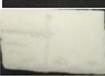
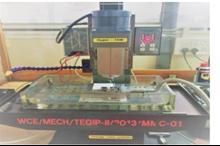
The micro-machining setup of synergy nano ‘c’ column verticalcenterisusedtoexperimentwithmicro-millingon PTFEshown inFig1. Fig2 showsthemicro-milling setup withdynamometer.
Table -1: Trialexperiment
Sr.No WorkPiece Dinolite Images Burr Generation 1

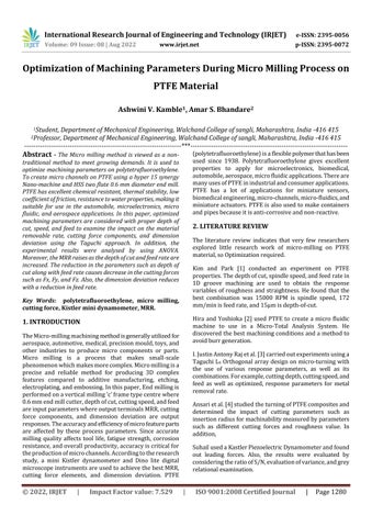
The workpiece is placed on top of the stationary dynamometer, which is located on the machine tool table. Theworkpieceisbolteddirectlyontothedynamometerto reducethemassonthedynamometerandtherebymitigate thenegativeimpactonitsdynamics.50*50*5mmworkpiece selectforexperimentation.
Accordingtotrialexperimentation,generatingburrduring micromillingprocessismentionedinTable1.
Large amount 2
Table -2: Resultsofthetrialexperiment
Less amount
Expt. Speed Feed DoC MRR Cutting force

Dim. Deviatio n No. (rpm) (mm/ min) (mm ) (mm3/ min) (N) (mm)
Fx Fy Fz
1 900 10 0.05 0.31 0.365 0.405 1.431 0.032
2 1800 50 0.15 5.42 0.681 0.816 3.600 0.124
3 1500 85 0.05 2.67 0.618 1.053 0.464 0.029
4 2000 90 0.15 8.24 0.054 0.018 0.895 0.011
5 2500 95 0.1 5.78 0.031 0.101 0.057 0.009
Table2.Showsthathands-ontrialexperimentreadings.Itis noticed that whenever feed rate was higher inside means above90mm/min,thenburrgenerationreduced.Also,MRR increaseswhenthedepthofcutincreases.Fxcomponentis lesscontribute,accordinglyFyandFzismostcontributingfor micro-milling.Herewithspeedandfeedincrease,dimension deviationwasdecreases.Whenthedepthofcutincreases,a slightlychangeinwidthandalsocuttingforceincreases.
Accordingtoresearchstudyandtrailexperienceparameter levelsandparametersselected,mentionedinTable3.
International Research Journal of Engineering and Technology (IRJET) e-ISSN: 2395-0056
Volume: 09 Issue: 08 | Aug 2022 www.irjet.net p-ISSN: 2395-0072
Sr.No Input 1 2 3
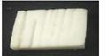
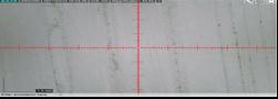
After The experimentation the workpiece checked by the Dino lite and check width of the channels for calculating dimensiondeviationshowninFig3.
Table -5: ResultsoftheL9 arrayexperiment
PTFEisaoneoftheplasticmaterial,6mm“HSS”‘2Flute’ type end mill cutter mostly used because of spiral type chipsarecreatedwhenexperimentationandthesearenot easilycomeoutfromtooltooth’s.
DoE is a statistical procedure for process design improvementandsolvingproblemsoccurringduringthe production of parts. Design of Experiments is an experimentalstrategyforexaminingtheeffectofmultiple factorsontheoutput.Taguchihasformulatedasystematic methodtotheDesignofExperimentsmethodtoimprove theproductqualityandprocessesshowninTable4.
iv. L9 orthogonal array:
Table -4: TaguchiL9 Array
Sr. No. Speed (rpm) Feed (mm/min) DoC (mm)
Arra y Feed Speed DoC Cutting forces MRR
Dim. Deviati ons mm/ min rpm mm Fx (N) Fy (N) Fz (N) mm3/m in %
1 10 900 0.05 0.36 0.40 1.43 0.349 5.5
2 50 900 0.10 0.73 0.50 2.31 3.95 5
3 90 900 015 0.89 0.69 4.10 8.424 4
4 10 1800 0.10 0.83 0.57 2.52 0.643 7.1
5 50 1800 0.15 0.68 0.81 3.11 4.13 13
6 90 1800 0.05 0.35 0.41 2.72 2.97 10
7 10 2700 0.15 0.72 0.85 2.50 0.957 6
8 50 2700 005 0.38 0.44 2.47 1.577 6.3
9 90 2700 0.10 0.53 0.5 3.18 5.841 10
Inthistrialexperiment,nineexperimentscompletedusing TaguchiL9array.ResultswereobtainedforMRR,cuttingforce anddimensiondeviation(Ref.Table5).Inaddition,inthis experiment,Minitabisused,whichisstatisticalsoftware.The statistical analysis of all the outcomes of trial runs was analyzedusingANOVA.
5.1. Graph of the MRR
Fig 3. Afterexperimentsanddinoliteimage
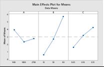
Fig 4. MRR,Maineffectplots
International Research Journal of Engineering and Technology (IRJET) e-ISSN: 2395-0056
Volume: 09 Issue: 08 | Aug 2022 www.irjet.net p-ISSN: 2395-0072
5.2. Graph of the cutting force Fx
5.5. Graph of the dimension deviation
Fig 5. Cutting Force Fx 5.3. Graph of the Fy: Fig 6. CuttingForceFy 5.4. Graph of the Fz:
Fig 7 CuttingForceFz,
Fig 8. Dimensiondeviation,MainEffectPlot
Table -6: ANOVAforMRR
Source DF Adj SS Adj MS F-Value P-Value
Speed(A) 2 4.171 2.086 1.85 0.237 Feed(B) 2 39.602 19.801 17.59 0.038 DOC(C) 2 10.645 5.322 4.73 0.107 Error 2 2.251 1.126
Total 8 56.668
Fig.4 showsthemaineffectplotforMRR.Thetrendobserved for feed rate is increasing MRR increases. According to ANOVA (Table 6.), the most significant factor observed is Feed Rate. According to MRR, the formula of Q is directly proportionaltothedepthofcut,thewidthofthechannel,and Feed.Thus,thevalueofMRRriseswithriseinfeedrateand depth of cut. Optimum set is Feed=90mm/min, Depth of Cut=0.15mm,Speed=900rpm
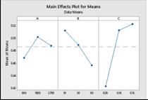
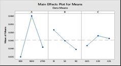
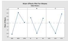
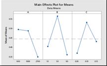
Table -7: ANOVAforcuttingforcecomponentFx
Source DF Adj SS Adj MS F-Value P-Value
Speed(A) 2 0.040891 0.020445 15.76 0.060 Feed(B) 2 0.070371 0.035185 27.12 0.036 DOC(C) 2 0.040967 0.020483 15.79 0.060
Error 2 0.002595 0.001297
Total 8 0.154824
The decrease in cutting depth and speed of the spindle reduces, the force Fx. According to the ANOVA table (Ref.
International Research Journal of Engineering and Technology (IRJET) e-ISSN: 2395-0056
Volume: 09 Issue: 08 | Aug 2022 www.irjet.net p-ISSN: 2395-0072
Table 7) Feed rate is the most significant factor. Cutting forcesovercometheresistancetorotations,sothedepthof cut was low then less energy consumed, and also low frictionalforcescomingonthetoolwhenthespeedandfeed increase.According to the main effect plot, optimum setis speed=2700rpm,feed=90mm/min,andthedepthofcutis 0.05mm.
Source DF Adj SS Adj MS F-Value P-Value
Speed(A) 2 0.004604 0.002302 1.63 0.054
Feed(B) 2 0.012162 0.006081 4.30 0.124
DOC(C) 2 0.001336 0.000668 0.47 0.003
Error 2 0.002827 0.001413
Total 8 0.020928
Thedecreaseindepthofcutandspeedofthespindlereduces the force Fy. According to ANOVA table (Ref. Table 8), the depthofcutismostimportantfactor.Also,thecuttingforce decreaseswhenthecuttingdepthandspeedwasdecreases, accordingtothedynamometeraxisdirection,Fyisfeedforce. FydirectionfrictionalforceincreaseswhenincreasesDoC. Optimumsetisdepthofcut=0.05mm,speed=900rpm,and feed=90mm/min.
Source DF Adj SS Adj MS F-Value P-Value
Speed(A) 2 0.004604 0.002302 1.63 0.380
Feed(B) 2 0.12162 0.006081 4.75 0.189
DOC(C) 2 0.001336 0.000668 3.47 0.679
Error 2 0.002827 0.001413
Total 8 0.020928
The decrease in the feed rate and depth of cut causes reductioninforcecomponentFz.AccordingtoANOVAtable (Ref. Table 9), a significant factor has been not found. In addition,wheneveralargerDOCvalueisgiven,cuttingforce increases. This might affect machining performance and causesvibration.So,higherforcesobservedinFzcomponent, theoptimumsetisspeed=900rpm,feed=50mm/min,and DOCis0.10mm
Source DF Adj SS Adj MS F-Value P-Value
Speed(A) 2 0.001052 0.000526 1.04 0.491
Feed(B) 2 0.000217 0.000108 0.21 0.824
DOC(C) 2 0.000058 0.000029 0.06 0.946
Error 2 0.001014 0.000507
Total 8 0.002340
Whenspindlespeedandfeeddecrease,decreasedimension deviation.Thesignificantfactorhasbeennotfound.Increases feedandspeedresultsonthechannel,widthincreases.Due tospindlevibrationandsoftmaterialpropertiesascompared tometal,dimensiondeviationincreases.Also,optimumsetis speed =900 rpm, depth of cut= 0.05mm and feed =90 mm/min.
1. The research was concluded the optimization of machiningparametersontheMRR,cuttingforce,dimension deviationduringmicromillingonPTFE.Themaineffectplot forMRRandANOVAshows,thevalueofMRRraiseswhen feed and DOC increases and optimum combination set is depth of cut 0.15mm, the feed rate 90 mm/min, and the spindlespeed900rpm.
2. According to the main effect plot and ANOVA analysis,Fxcuttingforcecomponentincreaseswhenthereis increaseinfeedrate.OptimumsetfoundwasDOC0.05mm, feedrate90mm/minandspeedofthespindle2700rpm.Fy componentisincreases when there isincrease in depthof cut.Optimumsetfoundwasthedepthofcut 0.05mmand feed rate 90 mm/min and spindle speed of 900 rpm. The cutting force component Fz could not found a significant factor.Theoptimumsetobservedwasdepthofcut0.10mm, feedrate50mm/minandspindlespeed900rpm.
3. According to the main effect plot for dimension deviation,theoptimumsetisdepthofcut0.05mm,andfeed rate90mm/minandspeed900rpm.
Theauthor,AshwiniV.Kamble,wishestothankWalchand College of Engineering in Sangli for their cooperation and facilitiesincompletingtheexperimentalstudy.
[1]DongMinKimandHyungWookPark,Micromachining characteristics of the polytetrafluoroethylene (PTFE) Materials.IWMF2014,9thinternationalworkshoponmicro factories(2014).
International Research Journal of Engineering and Technology (IRJET) e-ISSN: 2395-0056 Volume: 09 Issue: 08 | Aug 2022 www.irjet.net p-ISSN: 2395-0072
[2]Shin-ichiroHiraandMasatoYoshioka,Microcuttingof Polytetrafluoroethylene (PTFE) for Application of microfluidicDeviceskeyEngineeringMaterials.Vol.329,pp 577-582,(2007).
[3]I.JustinAnotonyRaj,P.VIjyakumar,TTM.Kannan,pankaj Kumar,R.Vijayaraghavanl,DesignOptimizationofturning parametersofPTFE(Teflon)cylindricalrodsusingANOVA Methodology,InternationaljournalofAppliedEngineering research.ISSN0973-4562,Vol.11,pp518-523,(2019).
[4] M. Sanjeev kumar, V. Kaviarasan, R. Venkatesan, Machining Parameter Optimization Poly Tetra Fluoro Ethylene (PTFE) Using Generic Algorithm International journalofModernEngineeringResearch,(IJMER)Vol.2pp 143-149(2007).
[5] Mohd Suhail Ansari and Deepak Sharmaand Sagar Nikam, Study of Cutting Forces and surface Roughness in Turning of Bronze Filled polytetrafluoroethylene InternationaljournalofadvancedmechanicalEngineering. Vol.4,pp151-160,(2014).
[6] Mustafa Gunay, Ihsan Korkut, Ersan, UlviSeker , Experiment investigation of the effect of cutting tool rake angleamaincuttingforce.JournalofMaterialsProcessing Technology.pp44-49,(2005).
[7] Nikolaos E. Karkalos P. Markopoulos, Athens, Greece, Thmas Makkai, Janos Kundrak, Miskolc, Hungary, Investigationoftheeffectofdepthofcutandcuttingforces duringfacemillingofsteelwitharectangularcuttinginsert. Cuttingandtoolintechnologicalsystem,(2019).
[8] Venkateswarlu G. Sharada R. and Bhagvanh Rao M. Polytetrafluoroethylene(PTFE)basedcomposites.Journalof chemical and pharmaceutical research. ISSN: 0975-7384 (2014).
[9] E. Dhanumalaan and Girish M. Joshi Performance properties and applications of polytetrafluoroethylene (PTFE)Advancedcompositesandhybridmaterials.Vol.1,pp 247-268,(2018).
2022, IRJET | Impact Factor value: 7.529 | ISO 9001:2008 Certified Journal | Page1285