International Research Journal of Engineering and Technology (IRJET) e-ISSN: 2395-0056

Volume: 09 Issue: 08 | Aug 2022 www.irjet.net p-ISSN: 2395-0072
International Research Journal of Engineering and Technology (IRJET) e-ISSN: 2395-0056
Volume: 09 Issue: 08 | Aug 2022 www.irjet.net p-ISSN: 2395-0072
Rushikesh Chame1 , Dr. M.R.
Vyawahare2
1M.E. (Transportation Engg. & Management) Department of Civil Engineering, Dr. Rajendra Gode Institute of Technology & Research, Amravati, Maharashtra, India 2H.O.D, Department of Civil Engineering, Dr. Rajendra Gode Institute of Technology & Research, Amravati, Maharashtra, India ***
Abstract – India is approaching towards becoming a developed country, but along with growth in development and research, the growth of population is also observed and is at a faster rate than earlier times. Growth in population means increased number of people, which creates a demand for more transport facilities. To fulfill these needs, one of the sectors that needs more construction is ‘Roads’. Roads are considered the easiest and most accessible mode of transport. Being easily accessible and considering the necessity, it is more important to plan and design the road in a safe, effective, economical way to achieve easy movement of traffic on road. Geometric design of highways has an important role in road design, and it is vital in the layout of road alignment. Earlier the designers used manual method which is really a time-consuming method, and cause errors increasing the project cost. AutoCAD Civil 3D, an application widely used by civil engineers and design professionals to plan and design the highway projects. Along with design of highways, the software also has tools and functions to design junctions, interchanges, grade separators etc. This paper focuses on geometric design of such type of interchange, ‘Trumpet Interchange’ using AutoCAD Civil 3D. The software is capable to design and produce drafts, reducing the time taken to implement changes and assess multiple options faster Although, number of factors impacts design of interchange, the geometric design with most efficiency, low traffic operation cost, and with safer travel at reasonable cost is final one.
Key Words: GeometricDesign,Civil3D,Accuracy,Safety
In today’s age, transportation plays a very vital role. Geometric Design is an important contributing factor in designofhighway.Indesignofhighway,safeandefficient travel is priority of the road design. Geometric design is dealing with horizontal and vertical curve, gradient, sight distance,andintersection
In older days, the drawings were made manually using differenttools.Amanualgeometricdesignconsumeslotof time,morechancesoferror,leadstoincreasedprojectcost. Also, the drawing in such scenario has only 2D view and mightnotbeeasytounderstand.
CivilengineersuseCivil3D,asoftwareapplicationwhichis used to design and plan projects for road projects,
constructionofbuildings,drainagefacilities.Additiontothis, it is also used for the construction of ports, dams, canals, embankments.Civil-3Disaveryuserfriendlysoftwareused for designing & drafting, which reduces the time taken to applychangesindesignandevaluationofmultiplescenarios Any change made in single place of project, dynamically updatesanentireproject.Thishelpsthedesignerstowork smarterandwithhighaccuracy.
Civil 3D hastheability tocreate3D modelsof any project andcaneasilyadoptsmall-andlarge-scaletasksofprojects. Thesoftwarecanprovide3Dvisualization,reducingthetime andhencereducingthebudgetoftheproject.
HarshilS.S.andShinkar(2016)usedcivil3Dfordesigningof bypassroadanddeterminedthathighaccuracyindesignand timeconsumptioncanbereducedbyusingCivil3D.
SagarPatil,SaniyaA.,SimranD.(2019)carriedoutstudyof Waghbil for geometric characteristics of road such as horizontalalignment,radius,grade,visibilityetc.
SaiRaghu(2018)considereddifferentgeometricfactorslike alignment,crosssection,profilesetcandexplainedgeometric designofhighwayandresultedthatgeometricdesignmust haveefficiencyformovementoftrafficandshouldbesafer.
MHD.KhajaN.andMHD.Aquil(2017)putforwardastudy about geometric design with the use of MX ROAD and concludedprecisedesignandaccuracyforgivendatausing software
VishalB.,(2020)researchedthegeometricdesignintermsof improved operation and safety. The important part in the research, which concluded that horizontal curve is always consideredlogicallysafebuttotravelinacurvesafely,the vehicleshouldbepushedbyenoughforceexternallytowards thecenterofcurvature.Iftheforceisnotenough,thevehicle candrifttotheedgesofcurveandleavethepath.
K.,VinodaA.(2018)carriedoutstudyofgeometricdesignof rural road using Civil 3D. They concluded that geometric design plays a key role in every road design and it plays majorroleintheroadalignmentdesign.Civil3Disthemost widelyuseddesignapplicationbycivildesignengineersand career professionals to design the projects. As most of the
International Research Journal of Engineering and Technology (IRJET) e-ISSN: 2395-0056
Volume: 09 Issue: 08 | Aug 2022 www.irjet.net p-ISSN: 2395-0072
tools used in Civil 3D are dynamic, a change made in one placeinaproject,automaticallyreflectsinentireprojectonce theprojectisupdated.Civil3Disalsogreatincompilationof projectfaster,helpfulfordesigners,hencesavingtime.
Shivam P., Atul, (2019) carried out design process for a flyoverandanintersectionusingCivil3D.Theresearchalso pointedoutthatCivil3Dasaresourcemakessuperelevation calculationeasyandfasterincompilation.
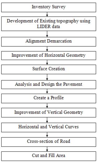
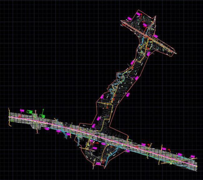
The Mumbai Nagpur Expressway known as Hindu HrudayasamratBalasahebThackeraySamruddhiMahamarg is a 6-lane wide 701 km long expressway is an accesscontrolled expressway in Maharashtra, India. It is also expandableto8lanesinfutureasperrequirement.Itisone of the longest Greenfield Road projects in the country connectingthecapitalsofthestate,MumbaiandNagpur.The projectisbeingledbyMaharashtraStateRoadDevelopment Corporation (MSRDC) and is designed by top consulting firmsofIndia.
heading away from the intended direction, gradually changing,andthencompletingthemovement byfollowing directly abound and entering the other road. Directional rampcanalsobea
a)Aconnectionbetweentheexpresswayandthecrossroad Thedrivertakesofftheexpresswayonleftandmergeswith thecrossroad
b)Forentrytoexpresswayfromcrossroad,thedrivertakes offonleftandmergeswiththeexpressway.
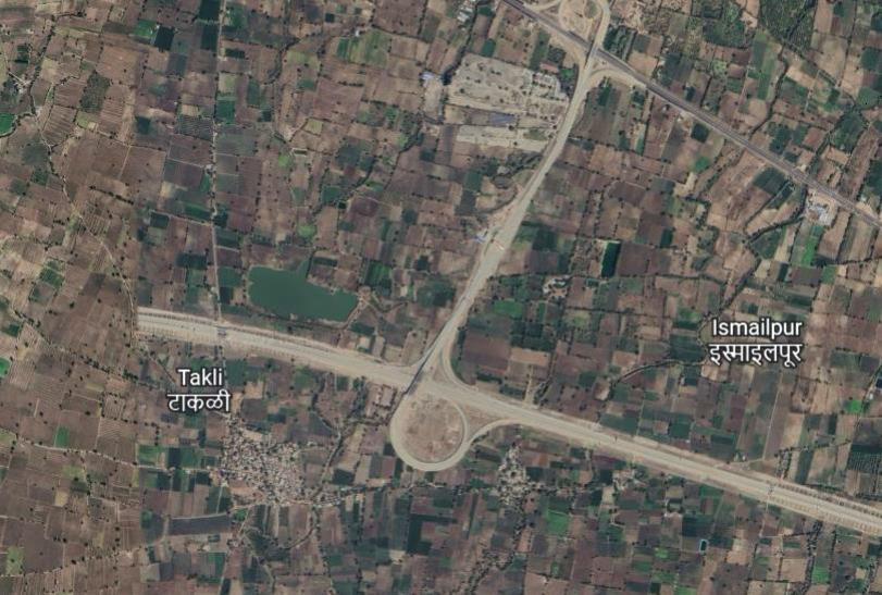
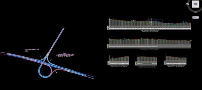
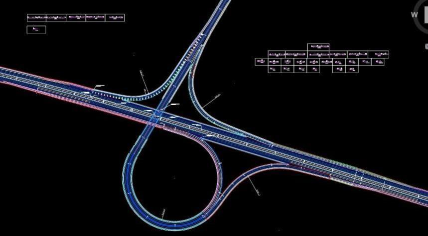
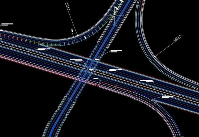
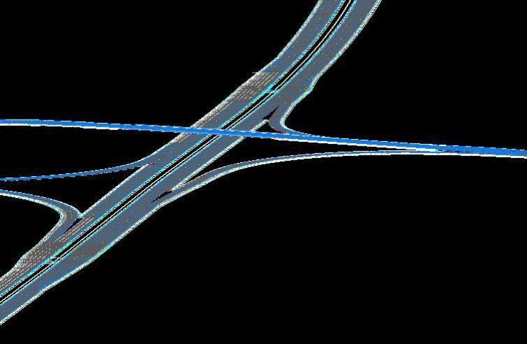
The selected interchange is a trumpet interchange which consists of total 4 ramps i.e., 2 directional ramps, 1 semi directionalrampand1loopramp.ThisinterchangeisatCH 447+064,alsocalledasDhulebypassandconnectstoNH52.
For desired turning movements ramps are provided at interchanges.TheconnectingrampsareclassifiedasDirect, Semi-direct and Loop ramps based on requirement of movement.
Looprampisforrightturnsaccomplishedbyaleftexitand turntotheleftthroughabout270°.Alooprampmayhave single turning movement (left or right or double turning movements(leftandright)ateitherorbothends.
Semi-directionalrampforrightturnsaccomplishedthrougha partial duration from the intended path. With semidirectional connection, the driver makes a left turn first,
Fig -2:PartsofTrumpetInterchange
Generally,trumpetandT-interchangearethepreferred configuration. Theadvantagesare
(a)suitableforthree-wayjunctionwithnoweaving (b)limitedrequirementofROWarea, (c)singlepointtollbooth
(d)providesarelativelyhighspeed(comparedtoloops) semi-directionalturningmovement.
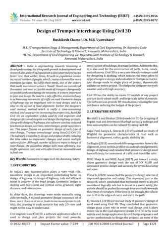
Fig -3:Methodology
International Research Journal of Engineering and Technology (IRJET) e-ISSN: 2395-0056
Volume: 09 Issue: 08 | Aug 2022 www.irjet.net p-ISSN: 2395-0072
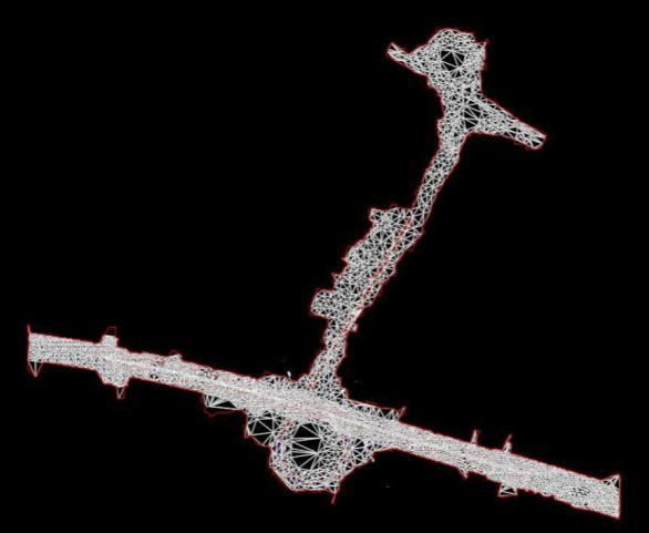
Creating an existing conditions surface and accumulating data on terrain, parcels, utilities, and other factors that could have an impact on the route design are commonfirststepsinroaddesign.Toplanthegeometryof roadways, one needs to have access to existing ground surface data. The survey company provides the site information.Elevations,easting,andnorthingareallpartof thesurveydata.ToimportthepointsintoAutoCADCivil3D andconstructtheexistinggroundsurface,choosethedata filecontainingthesurveypoints. Fig
International Research Journal of Engineering and Technology (IRJET) e-ISSN: 2395-0056
Volume: 09 Issue: 08 | Aug 2022 www.irjet.net p-ISSN: 2395-0072
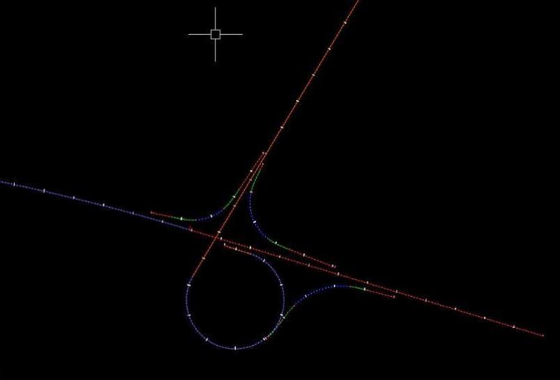
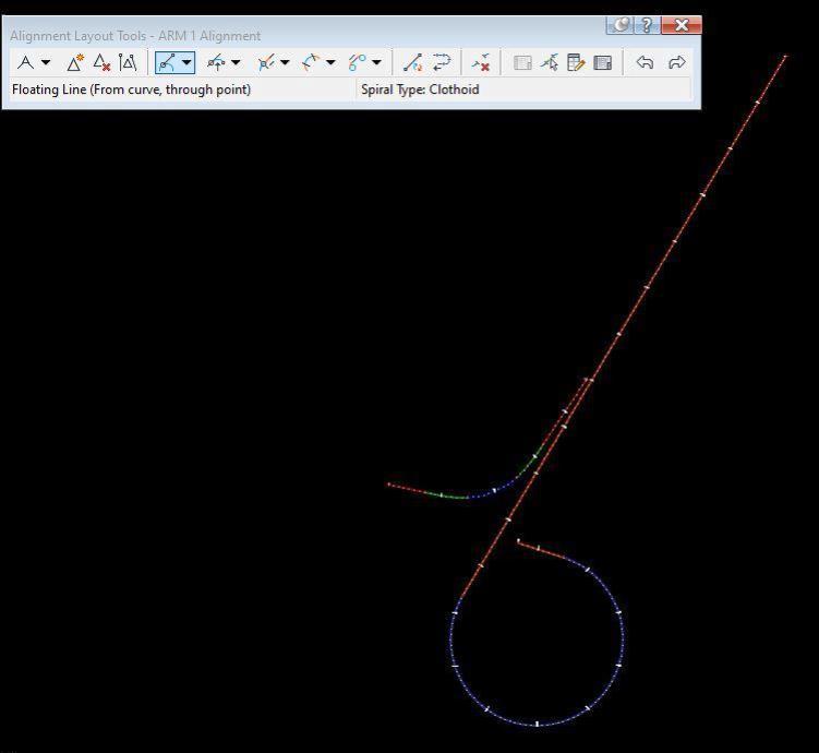
In order to prevent shock to the passenger when a movingvehicletransitionsfromastraightsectiontoafinite radiuscurve,atransitioncurvemustbeadded.Theshortest transitionperiodisdeterminedforvariousspeedsandradii.
Using the alignment designed, next step is to create a surfaceprofileviewtoplotaverticalalignmentwhichwill followthehorizontalalignmentsimultaneously.
Fig -12:CreatingaVerticalProfileusingProfileCreation ToolforARM1.
Fig -9:CreatingaSurfaceProfileViewusingSurface CreationTool.
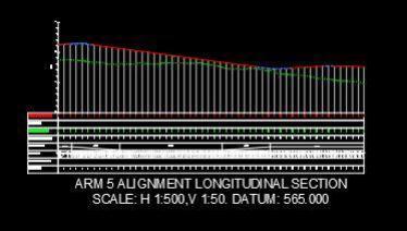
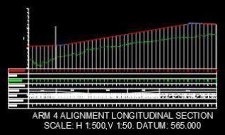
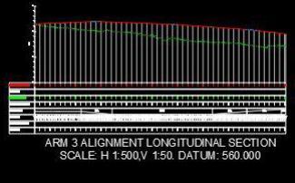
Using the Surface profile created, we can now draw Vertical Profile for the alignment, which will follow the directionofhorizontalalignmentaswell.Thiswillmakesure thatgradeoftheroadisproperforgoodridingexperience andalsointermsofdrainagefunctionaswell
Fig -13:CreatingaVerticalProfileusingProfileCreation ToolforARM3.
Fig -10:CreatingaVerticalProfileusingProfileCreation Tool.
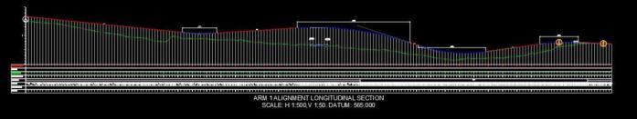
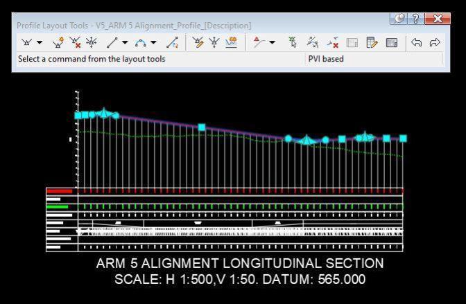
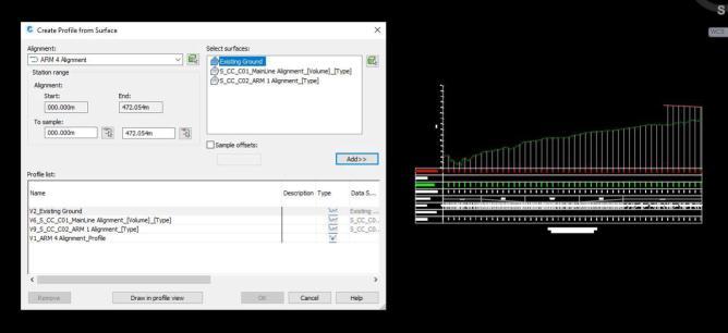
Fig -14:CreatingaVerticalProfileusingProfileCreation ToolforARM4.
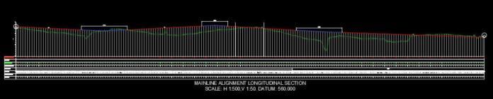
Fig -11:CreatingaVerticalProfileusingProfileCreation ToolforMainline.
Fig -15:CreatingaVerticalProfileusingProfileCreation ToolforARM5.
International Research Journal of Engineering and Technology (IRJET) e-ISSN: 2395-0056
Volume: 09 Issue: 08 | Aug 2022 www.irjet.net p-ISSN: 2395-0072
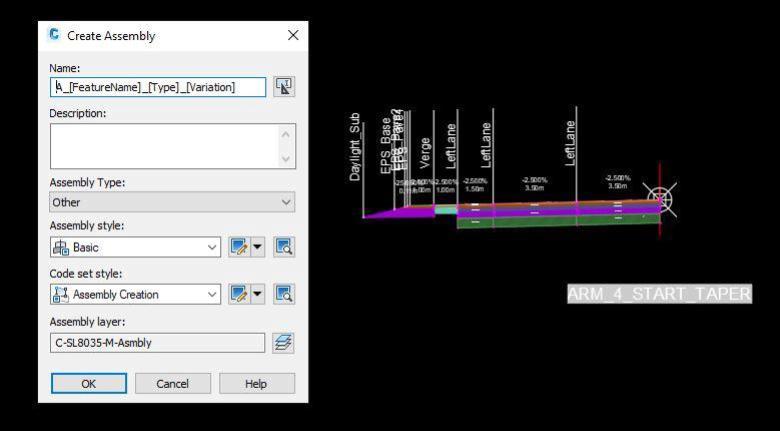
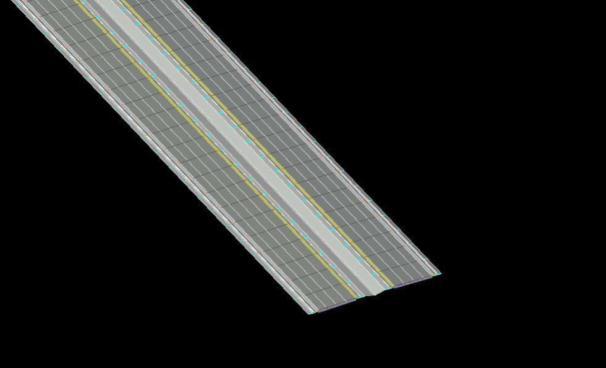
Purposeofassemblyistodefinecrosssectionalplatform for the designed alignemnet in Civil 3D Software. ‘Subassembly’ is a part of assembly. Assembly includes subassemblies such as shoulder, hardstrip, median, verge, carriagewaylaneforcreatingtypicalcrosssectionofroad. Thesesubassembliescanbeaddedtoeitheronlyrightorleft side of center of cross section or both side as per the requirement.
Fig -16:CreatinganAssemblyusingAssemblyCreation Tool.
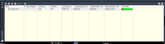
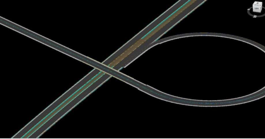
Fig -19:CorridorCreationTool.
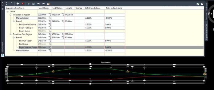
Atransverseslopeappliedbyincreasingthepavement's outeredgetowarditsinneredgetocounterthecentrifugal forceeffectandlessenthevehiclepotentialtoflipandskid laterally outward is Superelevation After determining the horizontalcurveradius,superelevationisapplied.The"Edit Superelevation"commandisusedtoapplysuperelevationto thealignmentsegment.
Fig -17:AssemblywithmultipleSubassemblies.
Fig -18:MultipleAssemblies.
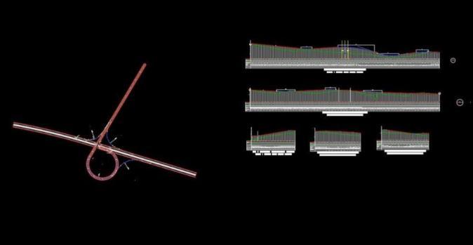
Usingthehorizontalalignment,verticalprofileandalong with assemblies created, we can create a corridor using corridorcreationtool.
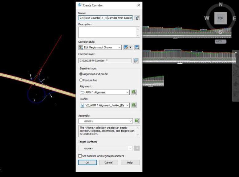
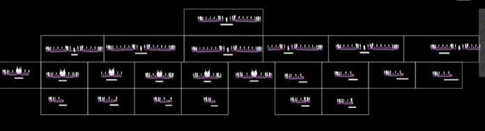
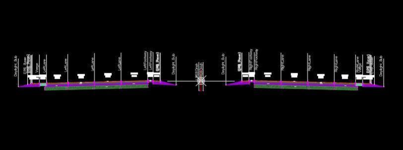
Fig -20:SuperelevationCalculationusingSuperelevation Editor
Civil 3D has a feature which helps to calculate the required earthwork ina road project After generating the ground surface and completing grade surface, the feature comparestheelevationdifferenceandcalculatesthevolume betweentwosurfaces.Selectthesurface,andtheninAnalyze Tabuse‘VolumeDashboard’
Fig -21:CutandFillcalculation.
International Research Journal of Engineering and Technology (IRJET) e-ISSN: 2395-0056
Volume: 09 Issue: 08 | Aug 2022 www.irjet.net p-ISSN: 2395-0072
[8] IRC:38-1988.“Guidelinesfordesignofhorizontalcurve”
[9] IRC-SP:23-1993.“VerticalCurvesforHighway”
[10] IRC-SP: 73-2015. “Manual for Specification and Standards for two laning of Highways with Paved Shoulder”
“M.E. Student (Transportation Engineering & Management), Dr. Rajendra Gode Institute of Technology&Research,Amravati“

AutoCADCivil3Dassistsincompletingthedesignprocessin a relaxed and comfortable manner while also saving a significantamountoftimeandeffort.Thecollectionoftraffic dataandtheexaminationoftheexistingstudyareaassistus inaligningtheroadinaneffectiveandfeasiblemanner.The spiraltransitioncurvesatisfiestherequirementforanideal transitioncurve.Intheproject,allcurvesareplottedinIRC Standard.
[1] HarshilS.S.andShinkar(2016).“PlanningandDesignof Proposed Bypass Road connecting Kalawad Road to GondalRoad,RajkotUsingAutodeskCivil3DSoftware.” IJSDR,Vol.1,453-458.
[2] Sagar Patil, Saniya A., Simran D. (2019). “Study Of GeometricFeaturesofRoadAndAccidentRate”IRJET Vol06,430-432
[3] SaiVeer,SidharthG,andJayeshJ.(2018).“AReviewof LiteratureonGeometricDesignofHighway.”IRJET,Vol 05,138-141.
[4] MHD. Khaja N and MHD. Aquil (2017) “Geometric DesignofaHighwayUsingMXROAD.”IJERIA,Vol.10,2534.
[5] VishalB.,S.Kumar(2020)“RoadwayGeometricDesign ResearchforImprovedSafetyandOperations”IJERIA, Vol.10,Issue9,42-44
[6] Nisarga,K.,andAmate,V.,(2018)“Geometricdesignof ruralroadusingAutoCADcivil3d”,IJSDR,Vol.05,I07.
[7] ShivamP.,YogeshB.,(2019) “Planning,designingand proposing a flyover road using Autocad civil 3d software”IJTIMESVol.5,Issue08,164-168
“H.O.D, Department of Civil Engineering, Dr. Rajendra Gode InstituteofTechnology&Research, Amravati“

2022, IRJET | Impact Factor value: 7.529 | ISO 9001:2008 Certified Journal |