International Research Journal of Engineering and Technology (IRJET) e-ISSN: 2395-0056

Volume: 09 Issue: 08 | Aug 2022 www.irjet.net p-ISSN: 2395-0072
International Research Journal of Engineering and Technology (IRJET) e-ISSN: 2395-0056
Volume: 09 Issue: 08 | Aug 2022 www.irjet.net p-ISSN: 2395-0072
1 Post Graduate Student, Department Of Civil Engineering, Ghousia College Of Engineering Ramanagara-562159 India.
2 Associate Professor Department of Civil Engineering, Ghousia College Of Engineering Ramanagara-562159 India. ***
Abstract – Thebehaviorofmulti-Storeybuildingsduring strong earthquake motion depends on the structural configuration. Most structures today have asymmetrical plans and vertical arrangements. A high degree of engineeringdesignerners’effectsisnecessarytoadequately analyzeandunderstandirregularconstruction.
From the observation of past earthquake structures with regular configuration, structures stay safe in earthquakes than structures with irregularities. Structure experience lateral displacements under earthquake loads. These works focus on studying the multi-Storey structure with the same area as an irregularly shaped building with Square, L, C and I shapes against seismic loads and seismic vibrations. The various structural behavior parameters suchasdisplacement, base shear, story drift & time-period are needed to be studied.
Key Words: Response spectrum, Static Equivalent & ETabs.
Earthquakes have historically occurred on the Indian subcontinent.TheIndianplateismovingintoAsiaatapace of about 47 mm/year, which is the main cause of the earthquakes' high frequency and intensity. Nearly 54% of India'sterrainisearthquake-prone,accordingtogeographic statistics. According to World Bank and United Nations research,by2050therewillbe200millioncityinhabitants inIndiawhowillbeatriskofearthquakesandstorms.The earthquake-resistantdesigncodeofIndia's[IS1893(Part1) 2002] newest version of the seismic zoning map of India assigns four levels of seismicity for India in terms of zone factors.
ZoneII: Thisistheleastseismicallyactivezone.
ZoneIII: Themoderateseismiczoneencompassesit.
ZoneIV: Thisareaisclassifiedasahighseismiczone.
ZoneV: Itisthemostseismicallyactiveregion.
Most structures today have asymmetrical plans and vertical arrangements. An unsafe coupled lateral reaction resultsfromalackofsymmetryinstructures,whichimpliesa
criticaleccentricitybetweenthemassandstiffnesscenters.A faulty designer might design and analyze a structure by ignoringvariouscriteria,leadingtoahazardousdesign.High degreesofengineeringanddesignereffortsarenecessaryto adequatelyanalyzeandunderstandanirregularconstruction.
Effectively designing and evaluating an irregular building requiresahighleveloftechnicalanddesignskills.Therefore, asecondmoredetailedstructuralanalysiswillberequired forirregularstructurestoimprovetheircomplicatedreaction toanearthquake.
Vertical abnormalities are one of the most frequent reasonsforstructurefailureduringearthquakes.Themost commonconstructionstofall,forinstance,werethosewith flimsylevels.Theeffectofverticaldifferencesonstructural seismicperformancethusbecomesofessentialimportance. Due to variations in stiffness and mass as they increasein height,thesebuildings’dynamicpropertiesdifferfromthose oftypicalbuildings.AccordingtothedescriptioninIS1893: 2016,theirregularityinbuildingstructuresisbroughtonby unevendistributionsofmass,weight,andstiffnessalongthe heightofthebuilding.Whensuchbuildingsareconstructed in high seismic zones, their analysis and design are more challenging.
A structure's collapseusually starts withcomponents thataremostunstableduringanearthquake.Thisweakspot is brought on by the irregularity of the structure's mass, stiffness, and geometry. These faults are seen in irregular formations.Theinfrastructureofthecityismostlymadeup of irregular systems. One of the main reasons systems fail duringearthquakesisirregularity.Theeffectofdeviationson asystem'stotalseismicoutputwillbemoreandmorecrucial. Maximumchangesinstiffnessandmasssetthesestructures apart from regular buildings in terms of their dynamic properties.Unevenmass,weight,andstiffnessdistributions along the height of the building may be the cause of the irregularity in the building structures. The research and designaremorechallengingwhensuchbuildingsarebuiltin seismicallyactiveregions.
Buildingirregularitiescanbeoftwotypes:
1.VerticalIrregularities
2.PlanIrregularities
International Research Journal of Engineering and Technology (IRJET) e-ISSN: 2395-0056
UsingthestructuralengineeringprogramETABSversion 18,thisstudyseekstostudyamulti-storystructurewiththe sameareaasanirregularlyshapedbuildingwithSQUARE,L, C,andIshapeagainstseismicloadsandseismicvibrations. The objective is to create a structure that is efficient, dependable,andhasenhancedductility.Severalsignificant goalsmustbeachievedtoensurethisachievement:
By evaluating a building's ability to withstand seismic loads and researching its capabilities and flaws, such as generaldisplacementsandunintendedbrittlebreakdowns
Aglobalanalysiscanbeusedtoevaluatethestructure's general behavior in terms of safety, effectiveness, and ductility. Additionally, by examining the findings of the frequenciesandgatheringthecriticaldisplacements,aswell asbyupgradingthestructureusinganappropriateseismic retrofittingapproachbyIS1893-2016&IS13935-2009,the weakspotsofthestructuremaybeverified.Theapproach used will take into account the structural behavior of the structureanditspresentcapacity.
Achieving these objectives can also help us better comprehendtheideaofseismicanalysisofplanirregularity structures. A limitation is imposed by disregarding the neighboring structure's exclusion and taking into account thatthebuildingisconstructedonthegroundsinceaportion ofitissupportedbyit.Thecapabilityofthecapabilitiesinthe employedsoftware,suchasETABS'sabilitytoapplyloadsto morecomplicatedshapes,isthesecondrestriction.Dueto thisrestriction,extraundefinedbeams,sometimesknownas fakebeams,areusedtocreateasimplergeometry.
The majority of structures in zones II and III are typicallybuilttowithstandseismicactivity.
buildingwithsevereirregularityproducesmoredeformation thanthosewithlessirregularity,particularlyinhighseismic zones.Andconjointlythestoreyoverturningmomentvaries inverselywithheightofthestorey.Thestoreybaseshearfor regular building is highest compare to irregular shape buildings.
Milind V. Mohod(2015):- Thispaperstudiedtheeffectsof planandshapeconfigurationonirregularshapedstructures. Theeffectofirregularity(planandshape)onstructurehas beencarriedoutbyusingstructuralanalysissoftwareSTAAD Pro. V8i. And he concluded that considering the effect of lateraldisplacementondifferentshapesofthebuildingofthe structure.Hehasbeenobservedthat,Plus-shape,L-shape,Hshape,Escapee,T-shapeandC-shapebuildingshavedisplaced more in bothdirectionsn (X and Y) in comparison to other remaining simple shaped building (Core-rectangle, Coresquare, Regular building).The storey drift being the importantparametertounderstandthedriftdemandofthe structureisconsideredwhilecollectingtheresultsfromthe software
Dr. Okay. R. C. Reddy, Sandip A. Tupatet.,al.(2014):-This researchhasstatedthatthewindhundredsandearthquake masses are estimated for a twelve storied RC framed constitution.Establishedontheresultsboughtthefollowing conclusionsaremade.Theearthquakeandwindhundreds rises with height of constitution. Wind loads are more valuable for tall structures than the earthquake loads. Constructionswillhavetobedesignedforloadsobtainedin eachrecommendationindependentlyforimportantforcesof windorearthquake.
Analysis of a conventional building with a regular layout
Inthisprojecteffort,irregularshapesincludingL,I, andCformstructuresweretakenintoconsideration.
Mohammedyousufetal.(2013)[2]:-Theaimofthispaperis tostudyondynamicanalysisofreinforcedconcretebuilding withplanirregularityforFourmodelsofG+5buildingwith onesymmetricplanandremainingirregularplanhavebeen takenfortheinvestigation.TheanalysisofR.C.C.buildingis carriedoutwiththeFEbasedsoftwareETABS9.5.Estimation ofresponsesuchas;lateral forces,baseshear,storeydrift, storeysheariscarriedout.Fourcrosssectionalvariationin columnssectionareconsideredforstudyingeffectivenessin resistinglateralforces.
Identification of abnormal building behavior in seismiczonesII,III,andIV.
Mohammed Rizwan Sultan,D. Gouse Peera(2015):This paper presents the study on dynamic analysis of multistoriedstructurefordifferentshapesthisstudyistograsp thebehaviorofthestructureinahighseismiczoneandalso to evaluate Storey overturning moment, Storey Drift, Displacement, Design lateral forces. They have considered differentshapeslikeRectangular,L-shape,H-shape,andCshape The complete models were analyzed with the assistanceofETABS9.7.1versionTheresultsindicatethat,
Yogesha A V and dr. Jagadish G. Kori (2018):- Thisaimof the paper is comparative analysis on symmetrical and unsymmetrical RC framed building using different type of dampers. Comparative analysis of symmetrical and asymmetric buildings using various dampers such as fluid viscousdampersandviscoelasticdampers.Codespecification IS 1893 (Part I): 2002 is used to analyze the structure according to the equivalent static and response spectrum methods. Modeling and analysis are performed using the softwareETAB2016.Theresults,namelyseismicparameters suchas displacement, floordisplacement,and floorthrust, aretabulatedandacomparativestudyofstructureswithand without dampers and in combination with fluid viscoelasticityisperformed.Imadeaviscoelasticdamper
Volume: 09 Issue: 08 | Aug 2022 www.irjet.net p-ISSN: 2395-0072 © 2022, IRJET | Impact Factor value: 7.529 | ISO 9001:2008 Certified Journal | Page968
International Research Journal of Engineering and Technology (IRJET) e-ISSN: 2395-0056
Volume: 09 Issue: 08 | Aug 2022 www.irjet.net p-ISSN: 2395-0072
The aim of this thesis is to provide information based on seismic analysis of normal and irregular buildings in accordancewithIS1893-2016,aswellasthosethathavebeen constructedinaccordancewithcodesandprocedures.
More specifically, the equivalent lateral load method and responsespectrumapproachisusedforthisthesistoanalyse thebuildinggloballyandchecktheentirebehaviourofthe system;concentrating mostly on thestructure's responses suchasdisplacement,storeydrift,baseshearandtimeperiod after using the seismic analysis, which is required by the code.
Inordertogainknowledgeaboutcommonseismicanalysisof plane and irregular buildings for different zones, a large amount of data, such as research papers, journals, and previoustheses,hasbeencollectedandthoroughlystudied.
The 3d Models of 4 buildings were modelled for seismic zonesII,III&IVintotal12femmodelsaremadeand itis designedforgravityaswellasseismicloadsusingtheIndian standardssuchasIS456:2000,IS875:2015,IS893:2016and IS13920:2016.
PrepareE-Tabsmodelswithplan irregularitieshavingsameplan area
Definingseismicloadsforvarious seismiczones
Plottingtablesandgraphsobtainedfrom E-Tabmodels
Comparingtheresultsofvariousplan irregularitiesforbestresults.
Twelvemodelsaremadetocomparetheresults
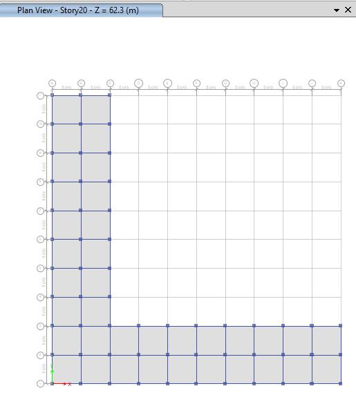
A. SquareModel.
Threesquareshapes(forZoneII,III,andIV)modelsaremade to scale in etabsand it issubjected to gravity loads as per IS1893-2016andthetheseismicresponseofthebuildings.
Figure5.2E-TabsSquareModel
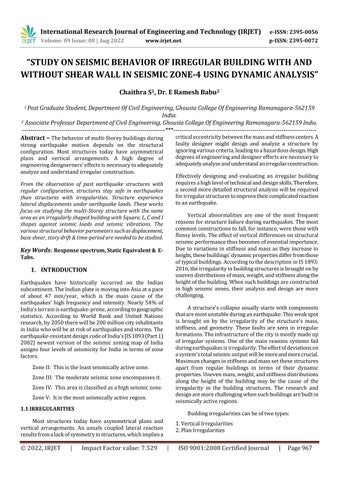
B. ModelL-Shape
ThreeLshapes(forZoneII,III,andIV)modelsaremadeto scale in etabs and it is subjected to gravity loads as per IS1893-2016andthetheseismicresponseofthebuildingsIV arenoted.
Figure5.3E-TabsL-ShapeModel
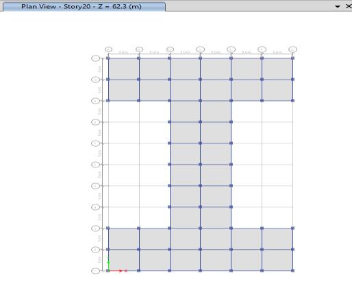
C. ModelC-Shape
ThreeCshapes(forZoneII,III,andIV)modelsaremadeto scale in etabs and it is subjected to gravity loads as per IS1893-2016andthetheseismicresponse.
© 2022, IRJET | Impact Factor value: 7.529 | ISO 9001:2008 Certified Journal | Page969
International Research Journal of Engineering and Technology (IRJET) e-ISSN: 2395-0056
Volume: 09 Issue: 08 | Aug 2022 www.irjet.net p-ISSN: 2395-0072
1.DeadloadasperIS:875(PartI)-1987
i)Selfweightofslab(150mmthick)-3.75kN/m2 ii)LoadingduetoFloorFinishes-1.50kN/m2
2.Frommasonrywalls–5.72kN/m3.
3.LiveloadasperIS:875(Part-II)-1987
i) Liveloadonfloor–3.00kN/m2 ii) Liveloadonroof-1.50kN/m2
4.Earthquakeload.IS:1893-2016
i) Zonefactor-0.1 ii) Zonefactor-0.16 iii) Zonefactor-0.24 ii)Soiltype-II iii)Importancefactor-1
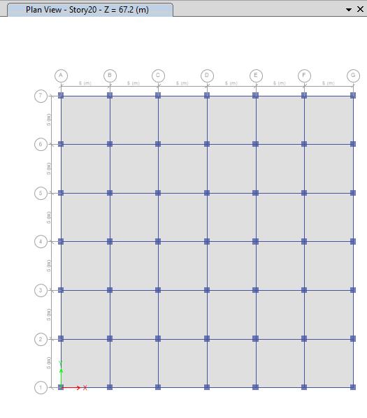
ThreeTshapes(forZoneII,III,andIV)modelsaremadeto scale in etabs and it is subjected to gravity loads as per IS1893-2016andthetheseismicresponse.
iv)TimeperiodinXdirection–1.05
TimeperiodinYdirection–1.05,0.81
Thestructurewasanalyzedfordeadload,liveload,seismic loadandtheircombinations.Thestructuraladequaciesof existingmemberswerecheckedaspertheguidelinesinIS: 456-2000andSP-16.
Thischapterpresentsresultsofseismicanalysisof all the models considered as per the model analysis. The resultsanddiscussionsgivenareconsideredindetail with referencetorequiredtablesandfigures.
The loads which have been used for the modelling are as follows:
Self-weightofthestructure
Floorfinish
Wallload
Typicalliveload
Roofliveload
Seismicload
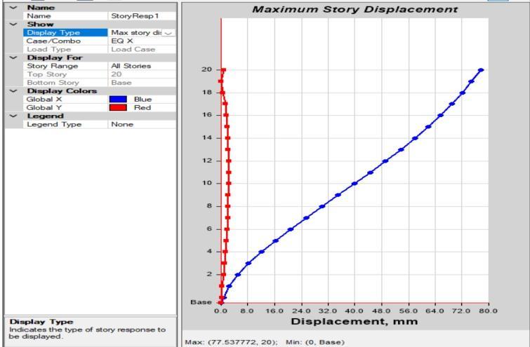
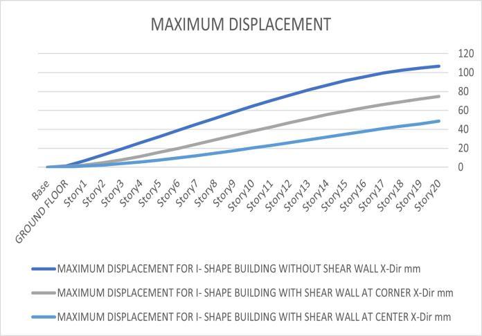
The maximum values of displacements are tabulated by comparingXandYdirections.Thevaluesofdisplacementof different models are obtained by subjecting the models to response spectrum analysis shows max displacement. Furtherthetabulatedresultsareplottedinagraphandcan beseeninthefigures.
2022, IRJET | Impact Factor value: 7.529 | ISO 9001:2008 Certified Journal | Page970
International Research Journal of Engineering and Technology (IRJET) e-ISSN: 2395-0056
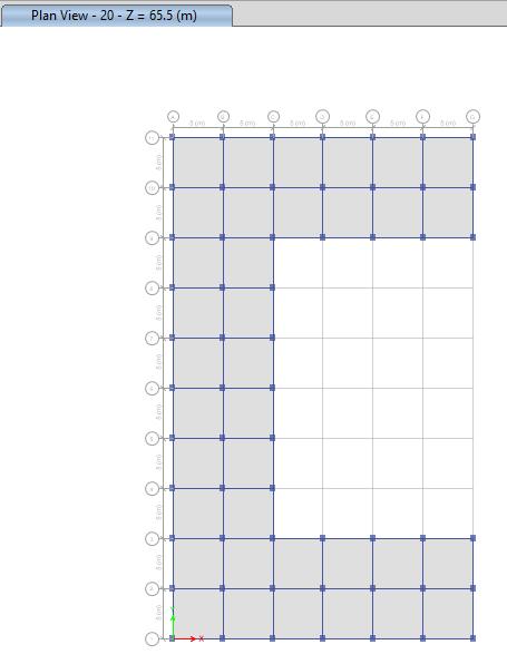
A. MaximumstoryDisplacementforsquareshape
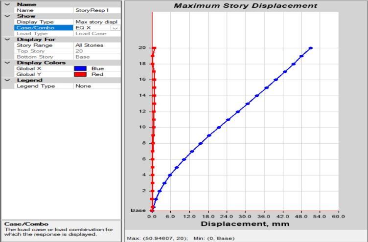
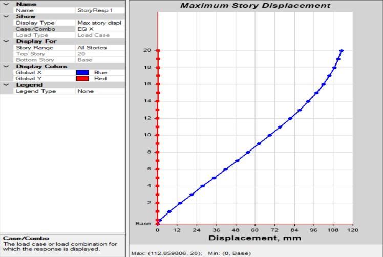
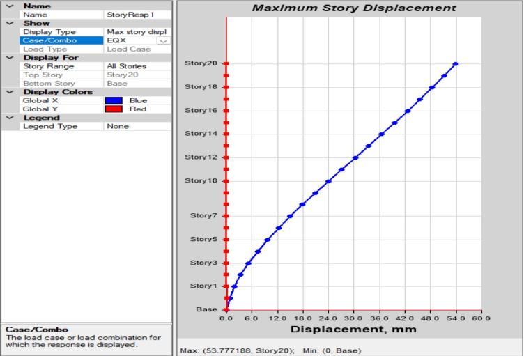
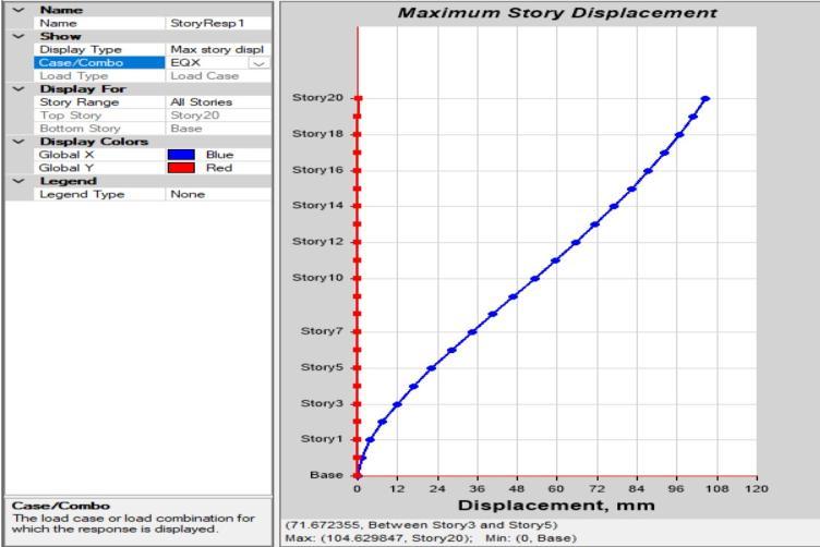
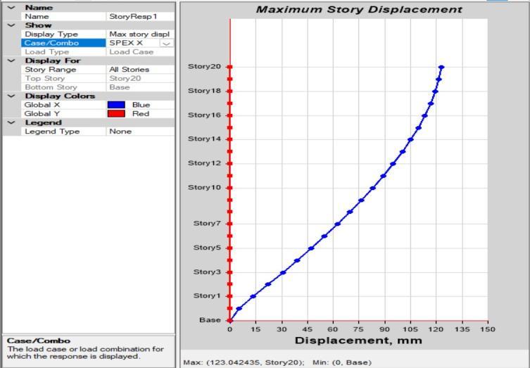
Fig5.1.1 Squareshapebuildingwithoutshearwall
Fig5.1.4 Squareshapebuildingdisplacement B. MaximumstorydisplacementforC-shapebuilding
Fig5.1.2 SquareshapebuildingwithshearwallatCorners
Fig5.1.5 C- shapebuildingwithoutshearwall
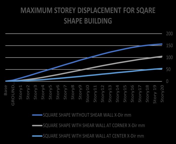
Fig5.1.3 SquareshapebuildingwithshearwallatCentre
Fig 5.1.6 C- shapebuildingwithshearwallatcenter
Volume: 09 Issue: 08 | Aug 2022 www.irjet.net p-ISSN: 2395-0072 © 2022, IRJET | Impact Factor value: 7.529 | ISO 9001:2008 Certified Journal | Page971
International Research Journal of Engineering and Technology (IRJET) e-ISSN: 2395-0056
Volume: 09 Issue: 08 | Aug 2022 www.irjet.net p-ISSN: 2395-0072
Fig5.1.7 C- shapebuildingwithshearwallatcorner
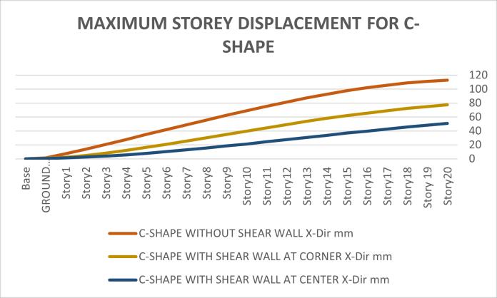
Fig5 2 0 L- shapebuildingwithshearwallatcorner
Fig5.1.8 C- shapebuildingMaximumstorydisplacement C. MaximumstorydisplacementforL-shapebuilding
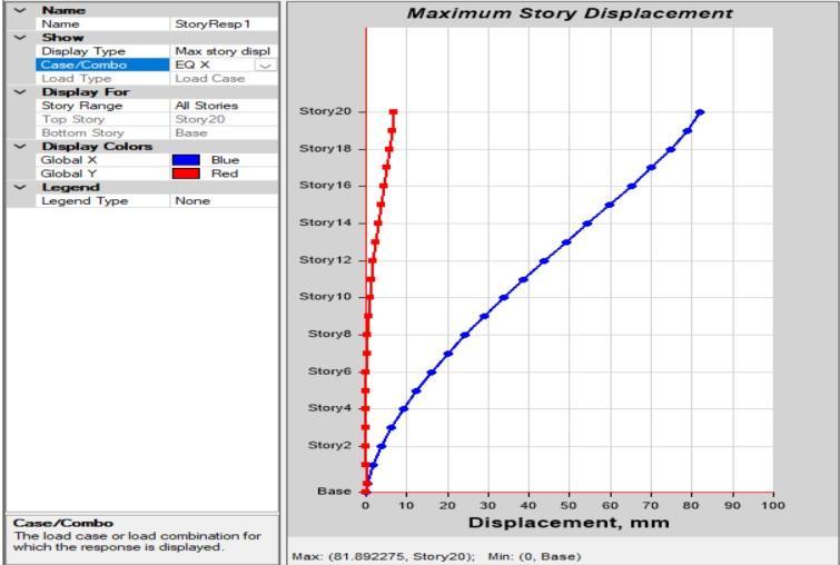
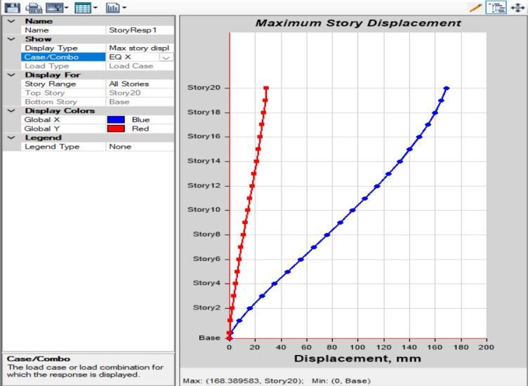
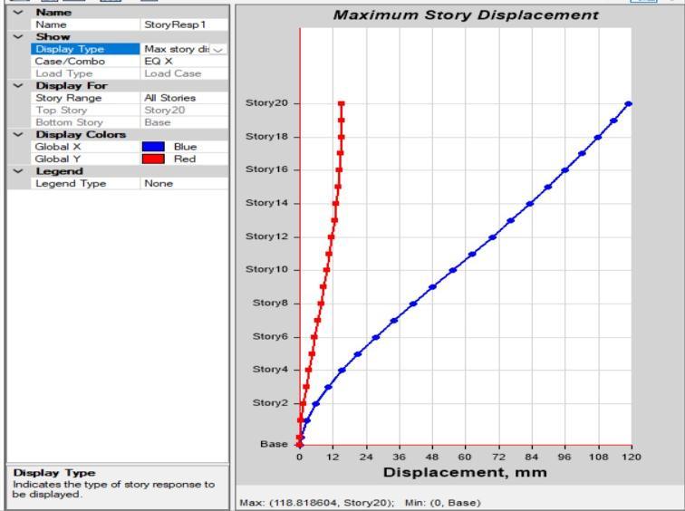
Fig5 2 1 L-shapebuildingwithshearwallatcenter
Fig5.1.9 L- shapebuildingwithoutshearwall
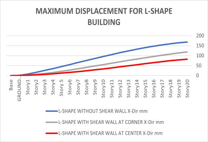
Fig5.2.2 L- shapebuildingMaximumstorydisplacement
2022, IRJET | Impact Factor value: 7.529 | ISO 9001:2008 Certified Journal | Page972
International Research Journal of Engineering and Technology (IRJET) e-ISSN: 2395-0056
Volume: 09 Issue: 08 | Aug 2022 www.irjet.net p-ISSN: 2395-0072
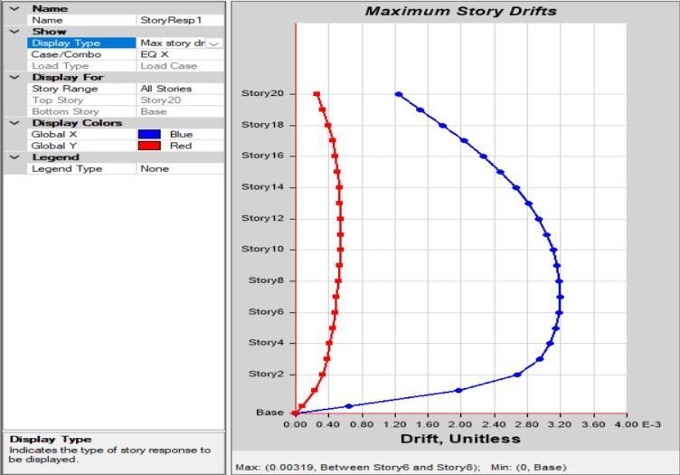
Fig5.2.3 I- shapebuildingwithoutshearwall
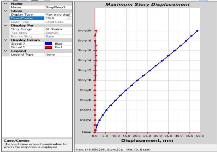
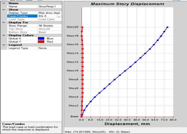
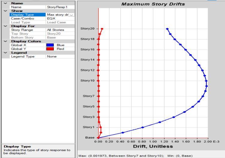
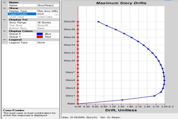
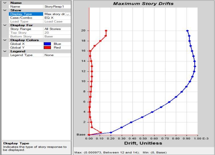
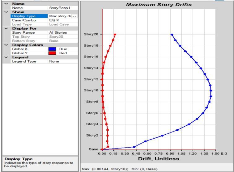
Fig 5.2.5 I- shapebuildingMaximumstorydisplacement 6.1.2 MAXIMUM STORY DRIFT
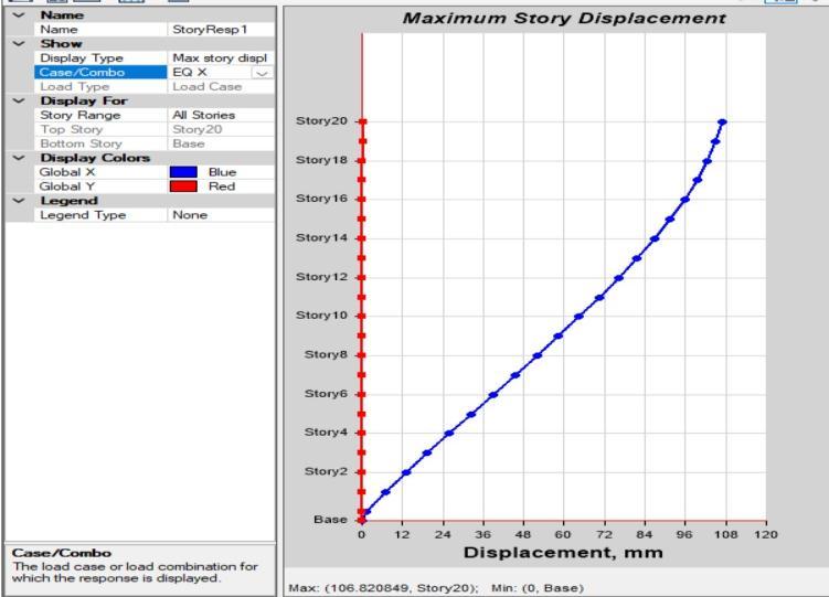
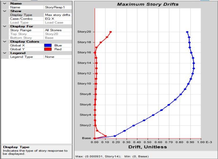
Fig 5.2.3 I- shapebuildingwithshearwallatcorner
Fig 5.2.6 Squareshapebuildingwithoutshearwall
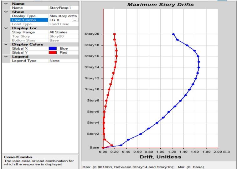
Fig 5.2.7 Squareshapebuildingwithshearwallatcorner
Fig 5.2.4 I-shapebuildingwithshearwallatcenter
2022, IRJET | Impact Factor value: 7.529 | ISO 9001:2008 Certified Journal | Page973
International Research Journal of Engineering and Technology (IRJET) e-ISSN: 2395-0056
Volume: 09 Issue: 08 | Aug 2022 www.irjet.net p-ISSN: 2395-0072
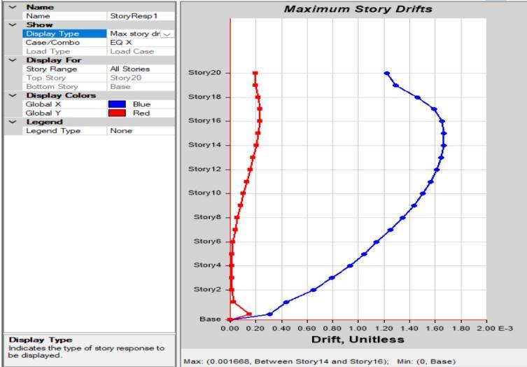
Fig 5.2.8 Squareshapebuildingwithshearwallatcenter
Fig 5.3.1 C-ShapebuildingwithshearwallatCorner
Fig 5.2.9 SquareshapebuildingMaximumStoryDrift
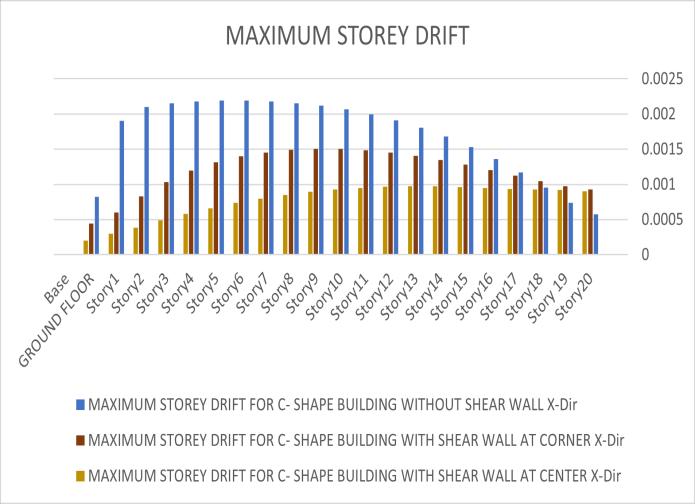
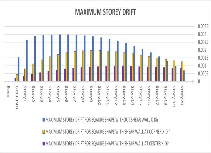
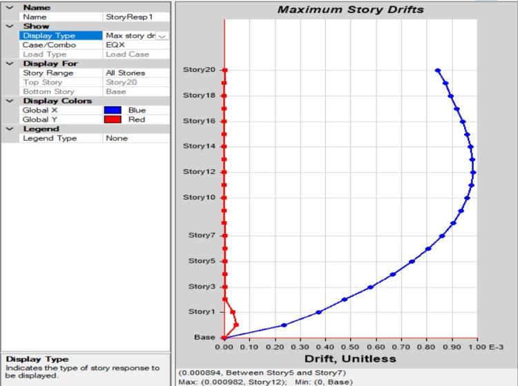
Fig 5.3.2 C-ShapebuildingwithshearwallatCenter
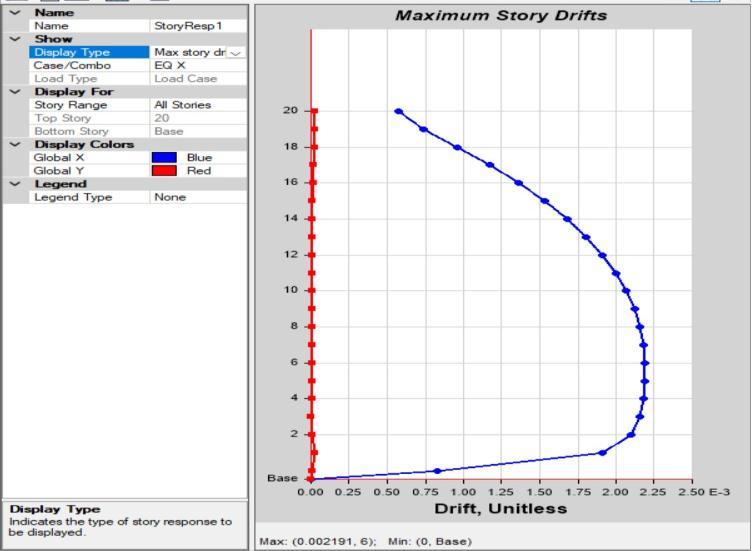
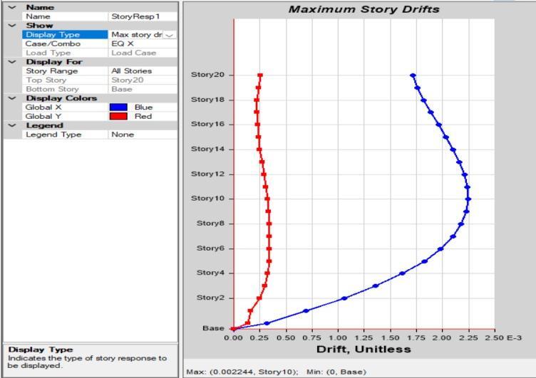
Fig 5.3.0 C-Shapebuildingwithoutshearwall
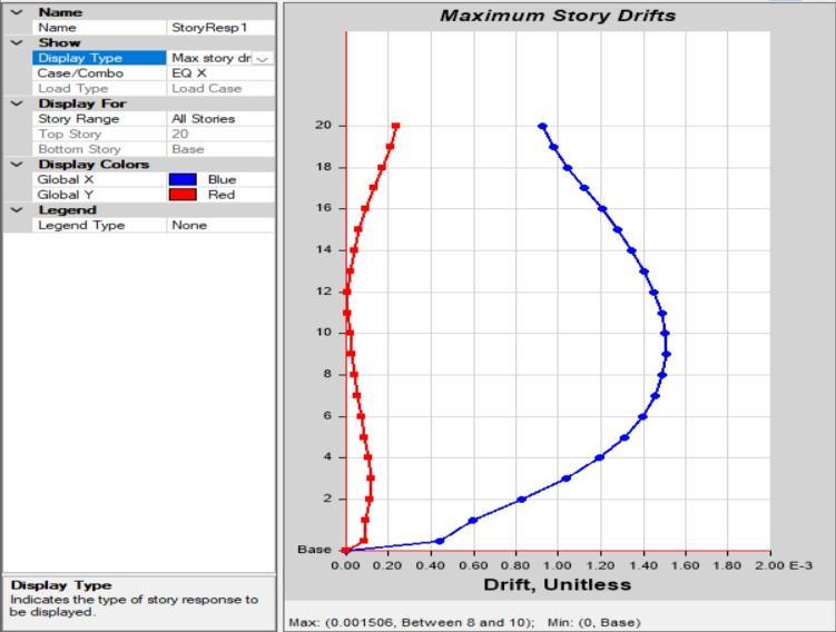
Fig 5.3.3 MaximumstoreydriftforC-Shapebuilding
2022, IRJET | Impact Factor value: 7.529 | ISO 9001:2008 Certified Journal | Page974
International Research Journal of Engineering and Technology (IRJET) e-ISSN: 2395-0056
Volume: 09 Issue: 08 | Aug 2022 www.irjet.net p-ISSN: 2395-0072
Fig 5 3 4 L-Shapebuildingwithoutshearwall
Fig5.3.7 MaximumStoreyDriftforL-ShapeBuilding
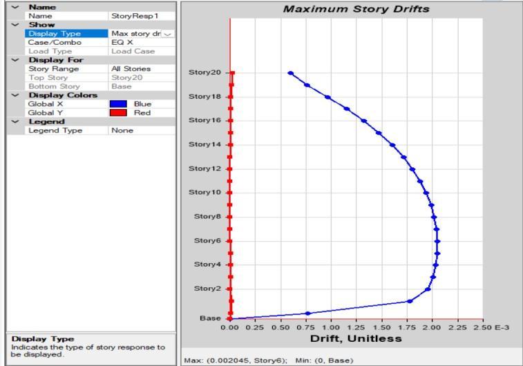
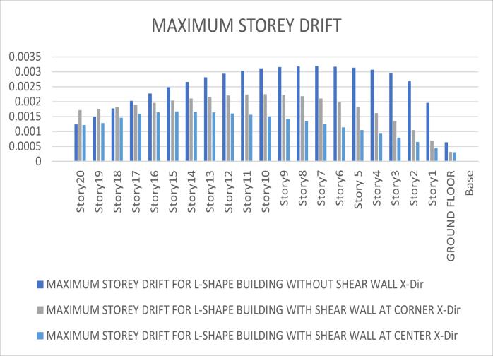
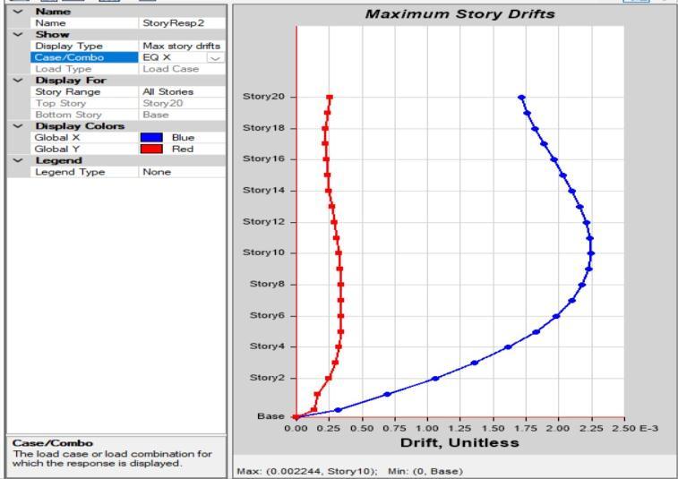
Fig 5 3 5 L-ShapebuildingwithshearwallatCorner
Fig 5.3.8 I-Shapebuildingwithoutshearwall
Fig 5.3.6 C-ShapebuildingwithshearwallatCenter
Fig 5.3.9 I-ShapebuildingwithshearwallatCorner
2022, IRJET | Impact Factor value: 7.529 | ISO 9001:2008 Certified Journal |
International Research Journal of Engineering and Technology (IRJET) e-ISSN: 2395-0056
Volume: 09 Issue: 08 | Aug 2022 www.irjet.net p-ISSN: 2395-0072
International Research Journal of Engineering and Technology (IRJET) e-ISSN: 2395-0056
Volume: 09 Issue: 08 | Aug 2022 www.irjet.net p-ISSN: 2395-0072
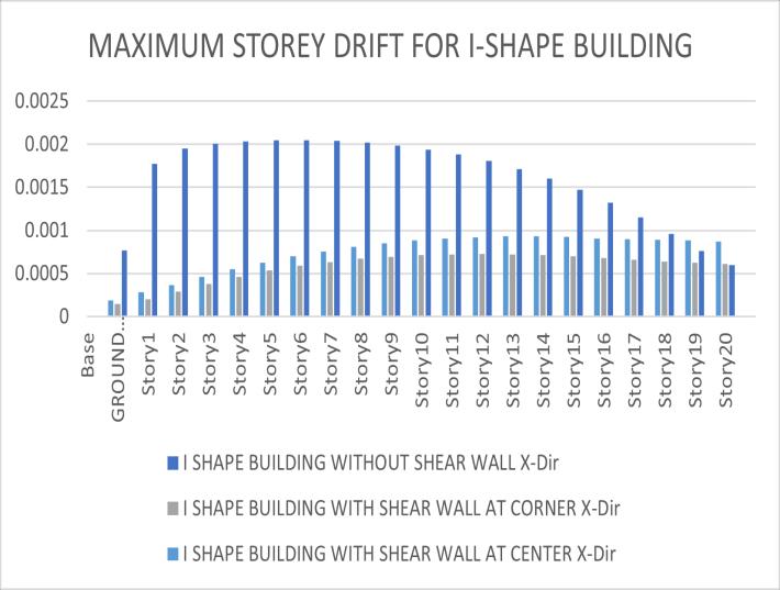
1. The inclusion of a shear wall in an RC Frame Structure minimizes Story Drift, making it safer compared to an RC FrameStructurewithoutashearwall.ShearwallsinamultistorybuildingminimizetheStoryDrift.
2. The appropriate location of shear walls significantly reducesthestructure'smaximumdrift.Summarilyprovision ofproperlydesignedshearwallsistheessentialneedforRC Framedstructuresinhigherearthquakezones.
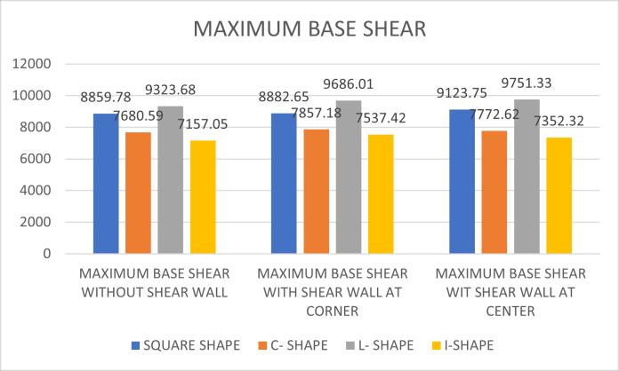
Fig 6 1 Maximumbaseshear
MODEL SQUARE SHAPE CSHAPE LSHAPE ISHAPE
MAXIMUMTIME PERIODFOR WITHOUTSHEAR WALL
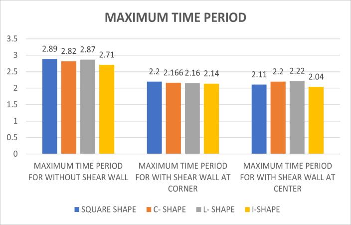
MAXIMUMTIME PERIODFOR WITHSHEAR WALLAT CORNER
MAXIMUMTIME PERIODFOR WITHSHEAR WALLATCENTER
2.89 2.82 2.87 2.71
2.2 2.166 2.16 2.14
2.11 2.2 2.22 2.04
3.Byconsideringthetwelvemodelsinseismiczone4and using response spectrum and equivalent static method of analysis.ItisconcludedthatModelI-Shapewithshearwall atcenter(withzone4)Givesthemostsuitableresults.Asit tendstotoreducetheDisplacement,storeydriftandtime periodinbothinXandYdirectionbygoodmargin.
1. Mohammed Rizwan Sultan and D. Gouse Peera(2015)“Dynamic Analysis Of Multi-Storey BuildingForDifferentShapes”InternationalJournal of Innovative Research in Advanced Engineering (IJIRAE).ISSN:2349-2163,Issue8,volume2(August 2015)
2. Milind V. Mohod “Effect Of Shape And Plan ConfigurationOn Seismic response Of Structure”International Journal Of Scientific & TechnologyResearchVolume4.2015.
3. Mohammedyousuf,P.M.shimpale(2013).Dynamic AnalysisofReinforcedConcreteBuildingwithPlan Irregularities. International Journal of Emerging TechnologyandAdvancedEngineering,Volume3, Issue9,September2013
4. Arvindreddy,R.J.Fernandes,“SeismicAnalysisofRC Regular and Irregular Frame Structures”, IJERT, Vol.2,Issue:5,Aug-2015.
5. Prof. S.S. Patil, ,Miss. S.A. Ghadge, ,Prof. C.G. Konapure, , Prof. Mrs. C.A. Ghadge. “ Seismic Analysis of High-Rise Building by Response Spectrum Method” International Journal Of Computational Engineering Research (Ijceronline.Com)Vol.3Issue.3,march2013
FIG. 6.2 Maximumtimeperiod
Followingsalientobservationsarederivedfromtheanalysis of G+20 story RC frame building with and without the provisionofshearwalls:
6. S.MaheshandDr.B.PandurangaRao”Comparisonof analysis and design of regular and irregular configuration of multi Story building in various seismic zones and various types of soils using ETABS.