International Research Journal of Engineering and Technology (IRJET) e-ISSN: 2395-0056

Volume: 09 Issue: 08 | Aug 2022 www.irjet.net p-ISSN: 2395-0072
International Research Journal of Engineering and Technology (IRJET) e-ISSN: 2395-0056
Volume: 09 Issue: 08 | Aug 2022 www.irjet.net p-ISSN: 2395-0072
1P.G. Student, Dept. Of civil Engineering, SVERI’s College of Engineering Pandharpur, Maharashtra, India
2Professor & Head, Dept. Of civil Engineering, SVERI’s College of Engineering Pandharpur, Maharashtra, India ***
Abstract - A Beam, ColumnandJoint is selectedfromthe structure, and to be modeled in FEA software. With the help of finite element analysis, the model of Beam Column Joint is properly modeledbyassigningpropertiesandafterthatproper meshing is done on the model. Further, by applying proper loading the Beam-Column Joint is analyzed. Finally, by Analyzing the model results like Stress, Straindistributionalso the total Deformation the strength is calculated and which is within the limit and structure performance is analyzed well. Retrofitting of currently usedbuildings has come into question with the determination of buildings’ performance levels due to earthquake force effect. In this sense, lots of retrofitting techniques have been applied for the retrofitting of current buildings beam columnjoint Inrecentyears,Forstrengthening and rehabilitation of existing structures Fiber Reinforced Polymer (FRP) composites have their advantage over traditional materials. The advantages such as corrosion resistance, light weight, high-strengthtoweightratio,andhigh efficiency in construction encourage civil engineers to use this material
advantageovertraditionalmaterials.Theadvantagessuchas corrosionresistance,lightweight,high-strengthtoweight ratio, and high efficiency in construction encourage civil engineerstousethismaterial.Effectivelateralconfinement isprovidedbyFRPjacketstotheconcretebeams,columns and joints that can improve their compressive strength, flexurestrengthandultimateaxialstrain.Retrofittingwith FRP materials provides successful solutions for strengthening,repairing,addingductility,rapidexecution, long-termdurability,andconsequentlylowerlifecyclecosts.
Ilki, Demir and Comert [1] StudiedontheretrofitofRC joints with FRP composites. This paper explains about typical failuremodes ofRC beam-column joints.The most common FRPretrofittingschemesandcontribution ofthe FRPretrofittingtobehaviourofexteriorbeamcolumnjoint is examined. For the study large scale structural tests on retrofitting beam column joints built with low strength concrete and plain bars by FRP sheets is done. It is found thatFRPscancontributesignificantlytotheperformanceof RCjointsagainstvariousdeficiencies.Theneedforstandard codeofpractiseinthefieldofFRPretrofittingispointedout fromthisstudy
Themaintenance,rehabilitationandupgradingofstructural members,areperhapsoneofthemostcrucialproblemsin civilengineeringapplications.Moreover,alargenumberof structural components such as beams, columns and beam columnjointconstructedinthepastusingtheolderdesign codesindifferent parts oftheworld.Beams,columnsand Beam-column joint deformations and strength affect the overallperformanceandloadcarryingcapacityofreinforced concretestructuresmakingthemsusceptibletoprogressive collapseduetofailureofoneormorebeam-columnjoints under gravity and earthquake loadings. Therefore, retrofitting of beams, columns and beam column joints is needed to maintain structural safety and reliability. Retrofitting of currently used buildings has come into questionwiththedeterminationofbuildings’performance levels due to earthquake force effect. In this sense, lots of retrofittingtechniqueshavebeenappliedfortheretrofitting ofcurrentbuildings.Columns,beams,jointsInrecentyears, Forstrengtheningandrehabilitationofexistingstructures Fiber Reinforced Polymer (FRP) composites have their
Subramani, Krishnan, Saravanan, and Thomas [2] Studied The Finite element method (FEM) has become a stapleforpredictingandsimulatingthephysicalbehaviorof complex engineering systems. The details of the finite element analysis of beam column joints retrofitted with carbon fibre reinforced polymer sheet (CFRP)carried out usingthepackageFEAarepresentedinthispaper
Ali and Gayathri [3] Studiedinvestigatedonthebehaviour ofRCbeamcolumnjointretrofittedwithvariousthicknesses ofCFRPandGFRPSheets.BeamcolumnjointofaG+3story building is considered. CFRP and GFRP sheets of varying thicknessareconsidered.Analyticalstudyforthemodelis done using FEA software and the results are discussed. Result shows that retrofitting using CFRP will give 50% morestrength(Von-Misesstress)ascomparedtoGFRP.
Vijaya, Shivakumaraswamy, Ravikiran [4] Studied Retrofitting of existing structures using Fiber reinforced polymer(FRP)technique.DifferenttypesofFRPsheetssuch as(CFRP)CarbonFiberReinforcedpolymer,(GFRP)Glass FiberReinforcedPolymer,(AFRP)AramidFiberReinforced Polymersheetstostrengthenthebeam-columnjoint
International Research Journal of Engineering and Technology (IRJET) e-ISSN: 2395-0056
Volume: 09 Issue: 08 | Aug 2022 www.irjet.net p-ISSN: 2395-0072
Carbon fiber-reinforced polymer, carbon fiberreinforcedplasticorcarbonfiber-reinforcedthermoplastic (CFRP, CRP, CFRTP) or often simply carbon fiber, or even carbon), is an extremely strong and light fiber reinforced polymerwhichcontaincarbonfiber.
ThereinforcementwillgivetheCFRPitsstrength and rigidity; measured by stress and elastic modulus respectively. Unlike isotropic materials like steel and aluminium, CFRP has directional strength properties. The propertiesofCFRPdependsonthelayoutsofthecarbonfiber and the proposition of the carbon fibers relative to the polymer
Despite its high initial strength to weight ratio,a degreelimitationofCFRPisitslackofadefinableendurance limit.Thismeanstheoreticallythatstresscyclefailurecannot beruledout.Whilesteelandmany otherstructuralmetals and alloys do have estimate fatigue endurance limits, the complexfailuremodesofcompositesmeanthatthefatigue failurepropertiesofCFRPforcriticalcyclicloadapplications, engineersmayneedtodesigninconsiderablestrengthsafety marginstoprovidesuitablecomponentreliabilityoveritslife service.
• Hightensilestrength
• Highstrengthtoweightratio
• Lowweighttovolumeratio
• Excellentfatiguebehavior
• Quickapplication
CFRP composite was able to strengthen the shear capacityaswellastheductilityofbeamcolumnjoint.
Inordertoincreasethestrengthandstiffness of beam column joint by using carbon fibre reinforcedpolymer.
the dimensions and properties corresponding to beamcolumn joints tested in the experiment. In this section, modeling,includingmeshing,detailsofbeam-columnjoints, ispresented.Thefinite-elementprogramANSYSWorkbench Version12isusedforthispurpose.Theelementdetailsof eachmaterialarepresentedsubsequently.
Concrete: To model the concrete an eight-node solid element,Solid65,isused.Thissolidelementhaseightnodes withthreedegreesoffreedomateachnodewithtranslations in the nodal x, y, and z directions. Plastic deformation, cracking in three orthogonal directions and crushing capabilitycanbeutilizedbytheelement.
Reinforcing Steel: Discrete modeling is used for reinforcement steel by defining the element between the nodes in the performed meshes. The steel for the finiteelementmodelwasassumedtobeanelastic–perfectlyplastic material with identical properties in tension and compression.
Link8 elementisusedtomodelthesteelreinforcement. Twonodesarerequiredforthiselement.Eachnodehasthree degreesoffreedom,whicharetranslationsinthenodalx,y, and z directions. Depending upon the applications, the element may be saw as truss element, a cable element, a reinforcing bar and a bolt. The three-dimensional spar element is having two nodes and each node having three translationaldegreesoffreedom.
SOLID 45 is a 3-dimensional element is used to model isotropicsolidproblems.Ithaseightnodes,witheachnode havingthreetranslationaldegreesoffreedominthenodalX, Y & Z directions. This element may use to analyze high deflection,highstrain,plasticityandcreepproblems.Ithas norealconstants
ANSYS is a finite element analysis tool for structural analysisandexplicitstudies.ANSYSoffersaneasyandflexible platformforperforminganalysisofstructuresormodelswith great accuracy. ANSYS consists of two working platforms called APDL and workbench among which workbench providesmoreautomatedoptionsfortheanalysisoperations.
Inordertoreducethefailureonbeamcolumn jointlikeCracking,underseismicload
The use of carbon fiber reinforced polymer into joint will enhance the strength and stiffness
Thefinite-elementanalysisofbareandstrengthened beam-columnjointsfirstrequiremodelingofthejointswith
This is usually done using numerical approximation in structuralanalysisistheFiniteElementMethod
This chapter deals with the parametric study. The parametricstudyisanalyzedbyusingsoftware’slikeANSYS 16 The parametric study focuses on the analysis of the structureandafterwhichanalysisofexteriorBeamColumn jointcarriedoutusingFEMsoftware,thisstudyhascarried out for concluding the importance of Beam Column joint strengthanditsbehavioronthestructure.
International Research Journal of Engineering and Technology (IRJET) e-ISSN: 2395-0056
Volume: 09 Issue: 08 | Aug 2022 www.irjet.net p-ISSN: 2395-0072
Table -1: Different material properties used in Ansys
Materials Concrete Steel
Density(kg/m3) 2300 7850
ElasticModulus(Mpa) 25000 200000 Poisson’sratio 0.15 0.30 Fck (Mpa) 25Fy(Mpa) - Fe500
Elementused SOLID65 LINK8
Table -2: Reinforcement Schedule For BCJ
TYPEOF MODEL Column Beam
Retrofitted CFRP CFRP
CSSIZE (mm) 400X400 230X450 Lengthof model(mm) 3000 2400 Longitudinal Steel 4NosT16 mm 4NosT16 mm
LateralTies 8mm@ 300mm c/c 8mm@ 300mmc/c
Table -3: Properties of CFRP Sheets
FRPSHEETS CFRP MODULUSOFELASTICITY(E) 23000Mpa POISSONSRATIO 0.22 ULTIMATETENSILESTRENGTH 3500Mpa SHEARMODULUS(G) 3270Mpa
Table -4 : Details of retrofitted on model used in Ansys
FRPSHEETS CFRP
MODULUSOFELASTICITY(E) 23000Mpa
POISSONSRATIO 0.22
ThicknessOfCFRPSheets 1.12mm NoofLayerWrapped 02
ABCJismodeledbyusingANSYS BCJhavingM25gradeofconcreteused After selection of the BCJ the geometric model (concrete and steel) is Prepared by taking proper dimensionsandassigningpropertiestothemodel Afterthatretrofitting
The above model is retrofitted by CFRP in Ansys meshingisdoneinAnsys applyingtheboundaryconditionforcolumn (bothendsarefixedfixed). Theboundaryconditionforbeam(oneendarefixed otherisfree). Applytheloadcenteroftheedgeofthebeamand analysisiscarriedout
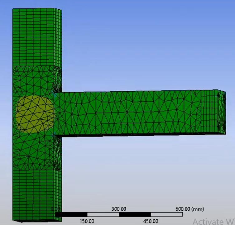
AbovefigureshowsthegeometryoftheBCJmodel preparedfortheanalysis.
Following figure shows The Geometry of selected retrofittedBCJmodel FirstlythegeometryofBeamColumnJointismodeledin ANSYSv16software.
Figure No 4.1 : The Geometry of selected retrofittedBCJ model
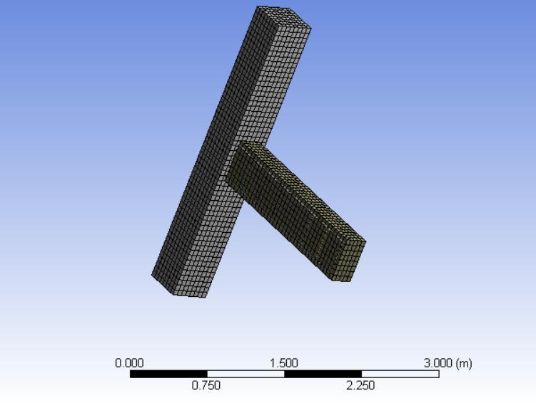
Reinforcement :
Followingfig4.2showsReinforcementdetailsofRetrofitted BCJ
2022, IRJET | Impact Factor value: 7.529 | ISO 9001:2008 Certified Journal | Page936
International Research Journal of Engineering and Technology (IRJET) e-ISSN: 2395-0056
Volume: 09 Issue: 08 | Aug 2022 www.irjet.net p-ISSN: 2395-0072
After that detail analysis of retrofitted BCJ like total deformation,maximumprincipalelasticstrain,shearstress ,normalstress,shearelasticstrain,equivalentelasticstrain, showninbelow.
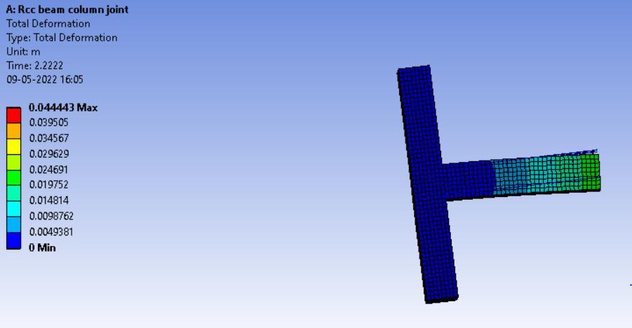
The Total Deformation obtained is tabulated in the Table.6 with the values and according to fig.4.4 the Joint showssafervalues.
Fig. No. 4.4 : Total Deformation of BCJ Solution Total Deformation
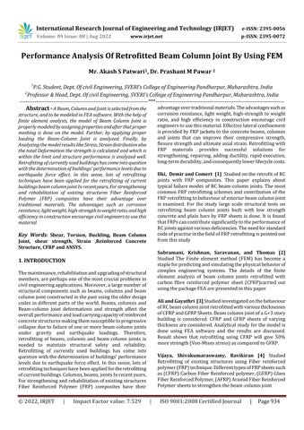
After the model in ANSYS v16 and after giving proper propertiesthemodelisrunfortheMeshing.Followingfig.4.3 showstheMeshedmodelofBeam-ColumnJoint
TheloadingappliedonBCJmodelthestaticremoteload fortheanalysisoftheBCJasfollowingtable
Table No 5 : Remote force of BCJ
Table -6: Total Deformation
Time[s] Minimum[m] Maximum[m] 1. 0. 4.4443e-002
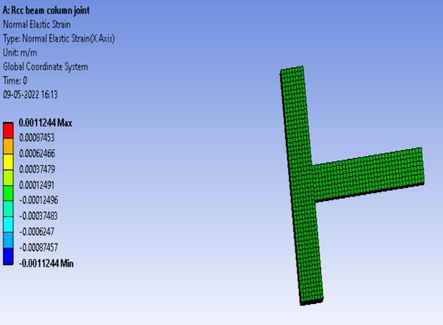
The Normal Elastic Strain obtained is tabulated in the Table.7 with the values and according to fig.4.5 the Joint showssafervalues.
Fig. No. 4.5 : Normal Elastic Strain of BCJ Solution Normal Elastic Strain
International Research Journal of Engineering and Technology (IRJET) e-ISSN: 2395-0056
Table -7: Normal Elastic Strain
Time[s] Minimum [m/m] Maximum [m/m]
1. -1.1244e-003 1.1244e-003
TheNormalstressobtainedistabulatedintheTable.7with the values and according to fig.4.6 the Joint shows safer values.
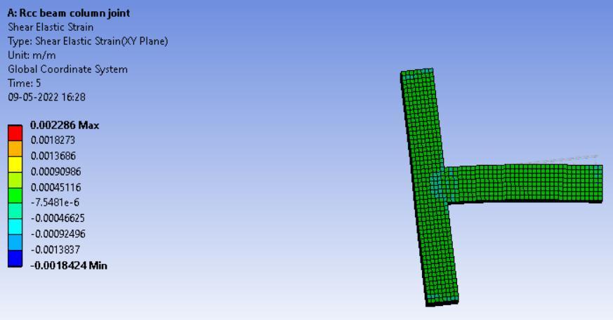
Fig. No. 4.6 : Normal Stress of BCJ Solution normal Stress
Table -8: Equivalent (von Mises )Stress
Time[s] Minimum[Pa] Maximum[Pa] 1. 60150 3.3821e+008
TheShearElasticStrainobtainedistabulatedintheTable.9 with the values and according to fig.4.78the Joint shows safervalues
Fig. No. 4.8 : Shear Elastic Strain of BCJ Solution Shear Elastic Strain
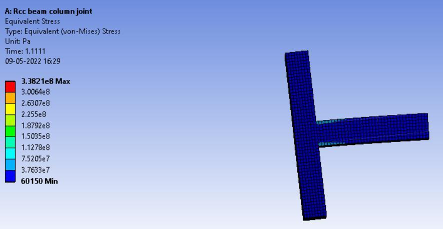
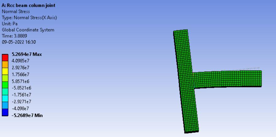
Table -7: Normal stress
Time[s] Minimum[Pa] Maximum[Pa]
1. -5.2689e+007 5.2694e+007
The vonMisesStressobtained is tabulated in the Table.8 withthevaluesandaccordingtofig.4.7theJointshowssafer values.
Fig. No. 4.7 : von Mises Stress of BCJ Solution von Mises Stress
Table -9: Shear Elastic Strain
Time[s] Minimum[m/m] Maximum[m/m]
1. -1.8424e-003 2.286e-003
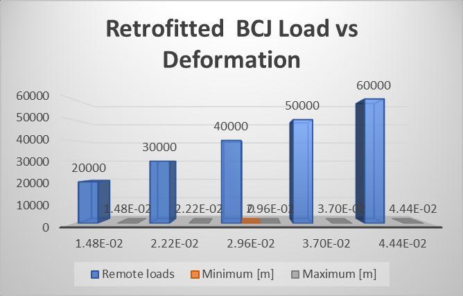
4.2 Load vs Deformation of Retrofitted BCJ
ThefollowingtableshowsappliedremoteloadsvsRespective minimum and maximum deformationof Retrofitted Beam columnjoint
Time [s] Remote loads[N] Minimum [m] Maximum[m]
1. 20000 0.
Volume: 09 Issue: 08 | Aug 2022 www.irjet.net p-ISSN: 2395-0072 © 2022, IRJET | Impact Factor value: 7.529 | ISO 9001:2008 Certified Journal | Page938
1.4814e-002 2. 30000 2.2221e-002 3. 40000 2.9629e-002 4. 50000 3.7036e-002 5. 60000 4.4443e-002
International Research Journal of Engineering and Technology (IRJET) e-ISSN: 2395-0056
Volume: 09 Issue: 08 | Aug 2022 www.irjet.net p-ISSN: 2395-0072
[1] N. Ganesan., P.V. Indira., and Ruby Abraham., Steel fibre reinforced high performance concrete Beamcolumnjointssubjectedtocyclicloading.ISETJournalof Earthquake Technology., Vol. 44, No. 3-4, Sept.-Dec. 2007,pp.445–456.
[2] A. Ilki, C. Demir and M. Comert (2013) “RetrofitofRC joints with FRP composites”, Istanbul Technical University,Turkey,https://www.researchgate.Net/ publication/259364431
[3] Vijaya,s., b.Shivakumaraswamy, and k. V. Ravikiran “Numericalmodelingonbehaviorofreinforcedconcrete exterior beam- column joint retrofitte with externally bonded fiber reinforced polymer (frp)”. International journal of research in engineering and technology 3 (2014).
As we see that the fig 4.9 shows the Load vs DeformationforRetrofittedBCJasweseenthatthe load increases the deformation increases. the minimum deformation for 60KN loading is 0 and maximumdeformationforloading60KNis0.044443 mwhichissafeandwithinlimit
theanalysisofthereinforcedconcretestructureby estimating forces and based on these forces the designistobecarriedout,Afterthatstudyfocused on the use of Finite Element Analysis to observe behaviorofExternalBeamColumnJoint.Furtherit wasaimedtoperformdetailanalysisofBeamColumn Joint in FEA Software to analyze the stress, strain distribution pattern. By study of Finite Element Analysis, it is observed that computer simulation offersproperpotentialtounderstandthebehaviorof beamcolumnjointundervarious loading. Detailed analysis is performed for Beam Column Joint for stabilityofjointunderconsideration,andaccordingto fig 4.4 it shows that maximum deformation of BCJ 0.044443mwhichsafeandwithinlimitandfig4.6and4.7 showsthemaximumNormalstressandvonMisesstresses is5.2694e+007Paand3.3821e+008Parespectively andNormal&ShearelasticStrainofBCJis1.1244e003and2.286e-003under60kNloadingthevalues withinlimitandjointissafe
ThisworkissupportedbyallexperiencedstaffandCivil Engineering Department of College of Engineering Pandharpur,Maharashtra,India,forprovidingusvaluable guidanceandANSYS16.0andFamilyandfriends
[4] Vijaya,s., b.Shivakumaraswamy, and k. V. Ravikiran. “Numericalmodelingonbehaviorofreinforcedconcrete exterior beam- column joint retrofitte with externally bonded fiber reinforced polymer (frp)”. International journal of research in engineering and technology 3 (2014).
[5] Mrs. S. M. Kulkarni, Dr. Y.D. Patil A State-of-art Review On Reinforced Concrete Beam-column Joints. Journal Of Information,Knowledge And Research In, ISSN:0975–6744.,Vol.2,Nov11-oct12,pp.94-98
[6] IS 456-2000, “Indian Standard Plain and Reinforced Concrete-Code of Practise” , Bureau of Indian Standards,NewDelhi
2022, IRJET | Impact Factor value: 7.529 | ISO 9001:2008 Certified Journal | Page939