International Research Journal of Engineering and Technology (IRJET) e-ISSN: 2395-0056

Volume: 09 Issue: 08 | Aug 2022 www.irjet.net p-ISSN: 2395-0072
International Research Journal of Engineering and Technology (IRJET) e-ISSN: 2395-0056
Volume: 09 Issue: 08 | Aug 2022 www.irjet.net p-ISSN: 2395-0072
1Student of M-tech (Electrical Drives and Control)
2Assistant professor, MIT Aurangabad (MH), India
3Head of Department, MIT Aurangabad (MH), India ***
Abstract - One of the most crucial components in a solar energy system is an inverter. A multilevel inverter is frequently employed as the connection point between a renewable energy source and the electrical grid. Due to its capacity to operate at high voltage, little switching losses, low dv/dt stress, which results in low presence of electromagnetic interference (EMI) in output, improved performance, and obtained good power quality, multilevel inverters have drawn more attention from researchers. In the design of multilevel inverters today, power electronics devices are increasingly used. However, the multilevel inverter's power electronics interface leads to harmonic distortion and poor power quality. Over the past 20 years, various multilayer inverter designs have been put out in an effort to reduce these harmonic distortions. A single-phase solar-integrated 25-level H-bridge multilevel inverter is suggested in this paper. To meet load demand, it is based on twelve independent solar PV arrays. It is recommended to use a hybrid topology to reduce the number of components and harmonics (like clamping diodes, DC Bus capacitor). The proposed model has been put into practice using MATLAB/Simulink.
In the modern era, renewable energy sources have drawna lot ofattention. duetothelack ofpollutionand the abundance of reserves. Consequently, the public usually supports the use of renewable energy. The multilevel inverterisa type ofconverterthatcanusedc voltages as inputs to generate the appropriate alternating voltage level at the output. Applications for multilevel inverters have primarily been found in renewable energy systems. the enhanced performance, low dv/dt stress power electronics switches, and innovativeswitchingtopologieshaveallledtoincreased multilayer inverter use in unconventional energy systems. The multilayer inverter produced high-quality waveforms with the least number of harmonics, which increased their appeal to PV systems. Numerous inverters with various topologies have been developed byresearchersinordertoattainhighefficiencyandhigh reliability. These inverters can be used in applications requiring medium and high power. Multilevel inverters
provide the right solution for the PV system in order to achieve high performance of renewable energy generation. This suggested setup had twelve standalone solar PV arrays and a 25-level H-bridge multilevel inverter. It is advised to use a cascading system with sinusoidalPWMcontroltoachievevariousvoltagelevels at the inverter's output side. The suggested modal's technicaltermsareshowninTable1.1.
Table 1.1.TechnicalTerms
Sr.no Components Specification
1 IGBT switches
2 Solal panel (single panel)
Internalresistance =1e-3ohms Snubberresistance =1e5ohms
Maximumoutputpower=287.5W
Voltageatmpp( )=28.75V
Currentatmpp( )=10A
Cellspermodule=54cells
For proposed model, constant solar irradiance is assumed i.e.,1000W and fixed atmospheric temperaturei.e., C
The study by S. Mohapatra et al. proposed inverter topologies. In that, the author looked at various switching topologies, including, flying clamped inverter, neutral point clamped inverter H-bridge inverter with cascadingNPCinverters,FCinverters,andCHBinverters all require more parts than the inverter that is being proposed.Ithasacomplicatedcircuitandhighswitching loss.Ahybridcascadedmultilevelinvertertopologywith fewer switching elements and dc sources has been designed. Without employing the technique of pulse width modulation, the author introduced the hybrid inverter. Results indicate output with reduced harmonic content[1].
The suggested approach uses a single PV source that operates in an asymmetrical manner. This mode provides eight positive and eight negative voltage levels (foratotalof17levels,including0V)withouttheuseofa separate switching mechanism. Eleven switches are provided in a cascading pattern to produce various voltagelevelsfromasinglePVsource.Theoutputofadc
International Research Journal of Engineering and Technology (IRJET) e-ISSN: 2395-0056
Volume: 09 Issue: 08 | Aug 2022 www.irjet.net p-ISSN: 2395-0072
source is increased using a dc-dc sumo converter. This increased the dc source's output that the inverter received. The output side of an asymmetrical mode of operation has seventeen voltage levels. The power electronics switches are controlled by an Atmega16 microprocessor. The proposed model is created using MOSFET. Simulink takes into account the R load. The proposed inverter has a very low total harmonic distortion,perthefindingsofthesimulation[2]
Ajmal Farooq et al. introduced new topology for low harmonic distortion. The authors proposed a novel topology for a multilevel inverter with seventeen levels for high power applications and fewest possible components.Lowswitchinglossandlowdv/dtstressare the outcomes of that. Two bidirectional switches, six unidirectional switches, and four DC sources make up the design of the suggested inverter. The suggested model provides seventeen voltage levels, comprising eightpositive,eight negative,andonezerovoltagelevel, using ten IGBTs and four standalone dc sources. The voltageofDCsourcesischosenusinga1:3ratio.IfV1is 25V,thenV2willbe75V,whichisthreetimesV1.The PWM approach is sinusoidal. Capacitor is used to compress harmonics. Proposed model has the advantaged of minimum harmonic distortion with in cascaded hybrid inverter with sine pulse width modulationtechnique[3].
Felipe Bovolini and Grigoletto propose a new five-level architectureforaninverterwithlowerharmoniccontent and no transformer in their paper, The PV system uses this topology. The inverter topology that is suggested utilizes reactive power. This proposed model provides a five-level single phase transformer- lessinverterusing a straightforwardmodulationmechanism.Circuitsemploy capacitors. Grid neutral point is connected to PV stack negative point to achieve minimal leakage current, or virtuallynil[4].
N. Kalaiarasi et al. discuss hybrid architecture for nine level inverters for photovoltaic applications in their paper, this suggested model employed a cascaded configurationofhalfbridgeinvertersconnectedinseries. CalculatedoutputattheACvoltagelevelis2*n+1.where, totalnumberofsourcesrepresentedbyn.Thetotalofall inverter output voltages is the inverter's overall output. IncomparisontotraditionalVSIandCSI,staircaseoutput is achieved with lesser harmonics and higher output voltage[5]
Different topologies for inverter operation and control strategies for multilevel inverters were represented by ZinaBoussadaetal.DiodeClampedInverterTopologyis one ofthem. The existence ofa dcbus on phasereduces the need for capacitors. This makes it impossible to employ this topology. Topology for Flying Clamped Capacitors. In that, there is only one dc source required
in this setup. The advantage is that balance flying capacitorsandclampingdiodesarenotrequired.Second one is Cascaded Topology. This topology is pretty straightforward. Based on a full- bridge converter coupled in a cascaded configuration, this topology creates a bridge converter. High power levels benefit greatlyfromthistopology[6]
The suggested multilayer inverter is designed utilizing a T-type inverter with sub switches of H-Bridges, as described by c. Dhanamjayulu et. al. It is possible to obtain 17 voltage levels with various loads using the staircase PWM approach. Applications involving facts and unconventional energy can use the proposed inverter. Less power switches were needed in the proposed model, which led to lower costs and better performance. More efficiency was obtained for both linearandnon-linearloads[7].
T Raju J et al. offer new topologies designed for multilevel inverters to generate 11 levels of voltage at the output side in their research paper. his topology recommended an inverter with fewer DC sources. As a result, in simple inverter circuit with good output performance. Harmonics present in inverter reduced by usingPWMwaveformtechnique[8].
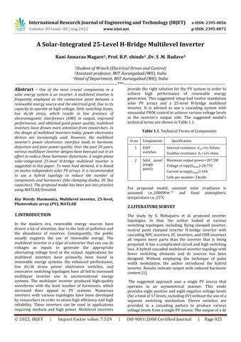
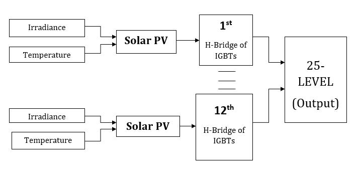
The most popular renewable energy source used to supplyelectricityissolarenergy.owingtotheappealing quality of solar energy. The suggested model includes a photovoltaic system with twelve independent solar PV arrays that uses to obtained a 25-level H-bridge multilevel inverter. To fulfill the maximum demand of load twelve standalone PV array is used Twelve hybrid bridges with a particular switching topology are used to convert the input dc voltage to an ac voltage with different levels on the output side. Switching losses can be reduced by employing IGBT. Figure 3.1 is a block diagramoftheproposedmodelofthe25-levelHMLI.The suggested 25-level hybrid cascaded multilevel inverter's output is seen in Figure 3.2.PWM controlled method is usedforswitchingtopologywithreferencesinewave. Fig- 3.1.BlockDiagramof25-LevelHMLI
International Research Journal of Engineering and Technology (IRJET) e-ISSN: 2395-0056
Twelvebridgesareusedtocreatethetwenty-fivevoltage levels on the output side. There are four separate IGBT switches in each. Forty- eight IGBTs in total are employed to produce 25 levels of output. A consistent sinusoidal reference signal is employed with the suggested modal PWM scheme. The output voltage may vary as a result of atmospheric factors. However, in order to prevent temperature variations, PV arrays operate on continuous irradiance and temperature. The technical informationabout thecomponentsisshownin table number 1. values of 24-hour temperature variations.However,aconstantsolarirradiationvalueof 1000Wm-2C and a fixed temperature value of 25 °C are assumed.IGBTshaveverylittlepowerlosswhenutilized aspowerelectronicsswitches.AllPVarraysarefedwith 1000Wm-2 of irradiance, and their operating temperature is 25°C. Twenty-five voltage levels is obtained with minimum harmonics contains that is 3.36 percent.
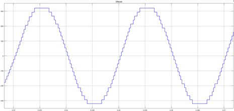
=PhotogeneratedcurrentinAmperes
=CurrentflowinginshuntresistanceinAmperes =DiodeCurrentinAmperes
ThecurrentisgovernedbyVoltageacrossthem, (2)
Where, =Voltageacrossresistanceanddiodesinvolts
V=Outputterminalsvoltageinvolts
I=OutputcurrentofsolarcellinAmperes =Seriesresistanceinohm
For the diode equation, Current flowing through the diodeis, ]-1} (3)
Where, Reversesaturationcurrentinamperes N=diodesidentityfactor
Fig 3.2. OutputofProposed25-LevelHMLI
Throughthephotovoltaiceffect, the solar system’s light energy is transformed into electrical energy. When solar radiation strikes a PV array (solar cell), current flows throughthem.TheproposedmodalPVarrayismodelled for internal parameters, ambient temperature, and sun light intensity [9]. Figure 3.3 depicts the PV array's comparablecircuit(solarcell).
Q=elementarycharge K=Boltzmann’sconstant T=absolutetemperature Byohmslow,Currentinshuntresistanceis, (4)
Put all values in equation (1) for generation of characteristicsequationforsolararray, (5)
Above equation shows obtained characteristics equation forPVarray.
Fig 3.3.
Fromabovecircuit,totalcurrentgivenby, I= + + (1)
Where, I=OutputcurrentofsolarcellinAmperes
Thecarrier- based correction technique employed in PWMtopology,whichisalsoeffectivetoreduceharmonic distortion,isusedtoconstructtheswitchingsequence.To accomplish the requisite twenty-five levels, the PWM controlled approach uses a sinusoidal signal as a reference with twenty-four reference triangular waves. For proposed modal, this approach is implemented in MATLAB/Simulink. Figure 4 depicts the switching patternforswitchk1.WheretheconstantPWMapproach isusedtoconstructtheswitchingsequenceforswitchk1. The switching sequence for switch K1 is produced using sineandsaw-toothwaveforms.(Figure3.4)
Volume: 09 Issue: 08 | Aug 2022 www.irjet.net p-ISSN: 2395-0072 © 2022, IRJET | Impact Factor value: 7.529 | ISO 9001:2008 Certified Journal | Page927
International Research Journal of Engineering and Technology (IRJET) e-ISSN: 2395-0056
MATLAB/Simulink, IGBT is utilized as a switch. The simulated waveforms in figure 4.2 are displayed. There are 25 levels of output ac voltage in the simulated waveform. Figure 4.3 Shows 25-level output with of HMLIwitht=0.2sec
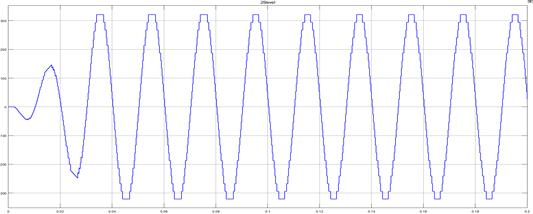
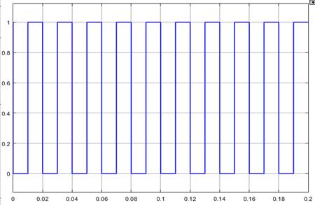
Fig 3.4. GeneratedPulsefor Switch.
Harmonicsrecordsupto13th harmonicsandafterthat values become minimum nearly equal to zero. To calculate harmonics theoretically amplitude of each harmonicsrepresentsintableno3.1
Table 3.1.HarmonicsVsAmplitudeofProposed Modal
Sr.no Harmonicsno. Amplitude(V) 1 1 100 2 3 1.8 3 5 0.6 4 7 0.7 5 9 0.6 6 11 0.3 7 13 0.59
PutallrecordedvaluesinTHDequation,asfollows
THD=√
THD=3.36%
The obtained THD is 3.36 percent theoretically. he fast Fourier transform (FFT Analysis) is used to calculate harmonic distortion in the Simulink model. FFT analysis is used to convert signals from the time domain to the frequency domain. The magnitude vs. frequency plot of theproposedmodalsignalsisgivenbytheFFTspectrum.
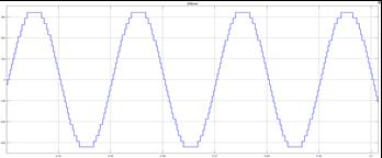
Figure 4.1 illustrates the implementation of the 25-level cascaded hybrid multilevel inverter with standalone PV array and switches using MATLAB/Simulation. Proposed mode consists of twelve hybrid bridges, each with four switches that are IGBTs, forty-eight IGBTs, and twelve standalone PV arrays to meet load demand. In
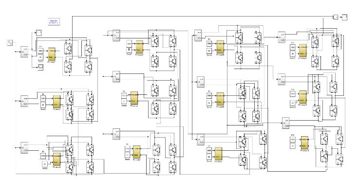
Fig 4.1 MATLABModalof25-LevelHMLI
Fig 4.2. 25-LevelHMLI
Fig 4.3. 25-LevelOutputofHMLIwitht=0.2sec
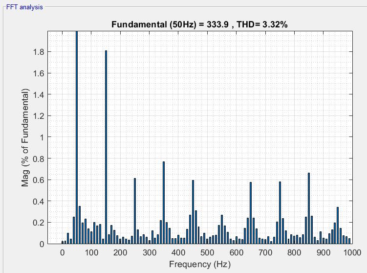
Fig 4.4 FFTSpectrumof25-LevelHMLI
Volume: 09 Issue: 08 | Aug 2022 www.irjet.net p-ISSN: 2395-0072 © 2022, IRJET | Impact Factor value: 7.529 | ISO 9001:2008 Certified Journal | Page928
International Research Journal of Engineering and Technology (IRJET) e-ISSN: 2395-0056
Volume: 09 Issue: 08 | Aug 2022 www.irjet.net p-ISSN: 2395-0072
Figure 4.4 of the simulation results displays the THD valuesintheproposedmodal,whichare3.32percent.To calculate THD, a fast Fourier transform analysis is used. FFT analysis is carried out in MATLAB/Simulink. The timedomainsignalisconvertedtothefrequencydomain during FFT analysis. The response signal magnitude versusfrequencyrelationshipispresentedonagraph.
Eight PV panels and a topology with a 17-level inverter weresuggestedbyMuhammadHamzaShahbazetal.[10]. The reference model, which included four power electronic switches in eight bridges, produced a THD of 6.69%. As a result, this paper has produced cutting-edge andhighly important results thatarelacking inthe body ofexistingknowledge.Table3providesacomprehensive comparison. Our primary contribution is the use of a Hbridge inverter to produce 25 levels of voltage output, andwehaveintegratedthisHMLIwithaPVarrayrather than DC supply. Only 17 levels were reached in the conventional model, which has a higher THD and lower dependabilitythanthesuggestedapproach.
Table5.1ComparisonwithaReferenceModel
Sr, no. Parameters Reference model Proposed model 1 NumberofOutputLevel 17 25 2 NumberofH-Bridges 8 12 3 NumberofSwitches 32 48 4 TotalHarmonicDistortion 6.9% 3.36%
6
A Twenty-Five-Stage H-bridge multilevel inverter model thatintegratessolarPVisdevelopedinthispaperforuse in high power applications. The suggested model uses twelve independent PV arrays rather than dc sources to meet load requirements. For output, a cascading arrangementisused.ItusesaPWMcontrolledtechnique. Using MATLAB/Simulink, the proposed model's implementation is simulated. Results indicate that with high power, THD is almost is very low i.e. 3.36 percent (AsPerIEEEStandards).
[1] S.K.Mohapatra,A.Khadiratna,A.K.Behera,P.Jena,S. Nayak and B. K. Prusty, "Design and simulation of hybrid cascaded multilevel inverter," 2020 International Conference on Computational IntelligenceforSmartPowerSystemandSustainable Energy (CISPSSE), 2020, pp. 1-5, doi: 10.1109/CISPSSE49931.2020.9212243.
[2] JayalekshmiOB,RajiKrishna,2020,ASinglePVSource based 17 Levels Module for Multilevel Inverter, INTERNATIONAL JOURNAL OF ENGINEERING RESEARCH & TECHNOLOGY (IJERT) Volume 09, Issue 06(June2020),
[3] Ajmal Farooq,1 Shanshan Tu,2 Fiaz Ahmad,3 Muhammad Zeeshan Malik,4 Obaid U. Rehman,5 Ghulam Hafeez,1 and Sadaqat ur Rehman6 Research ArticleAseventeenmultilevel high-powerapplication inverters with low total harmonic distortion. | Open Access Volume 2021 |Article ID 9982187 | https://doi.org/10.1155/2021/9982187
[4] Grigoletto, Felipe. (2019). Five-Level Transformerless Inverter for Single-Phase Solar Photovoltaic Applications. IEEE Journal of Emerging and Selected Topics in Power Electronics. PP. 1-1. 10.1109/JESTPE.2019.2891937.
[5] 1N. Kalaiarasi, 2 Subhranshu Sekhar Dash,3 S.Paramasivam,4RamazanBayindi “HybridCascaded Nine Level Inverter using Dspace controller for Standalone Photovoltaic Applications” 978-1-53862095-3/17/$31.00@2017IEEE.
[6] Z. Boussada, O. Elbeji and M. Benhamed, "Different topologies and control techniques of multi-level inverter: A literature survey," 2017 International Conference on Green Energy Conversion Systems (GECS), 2017, pp. 1-5, doi: 10.1109/GECS.2017.8066187.
[7] C. Dhanamjayulu, D. Prasad, S. Padmanaban, P. K. Maroti, J. B. Holm-Nielsen and F. Blaabjerg, "Design and Implementation of Seventeen Level Inverter with Reduced Components," in IEEE Access, vol. 9, pp. 16746-16760, 2021, doi: 10.1109/ACCESS.2021.3054001.
[8] Raju, J. & Thamilmaran, A. & .M, Priya. (2017). A case study: Analysis of single phase and hybrid cascade multilevel inverter with PWM and level inverters. International Journal of Mechanical Engineering and Technology.8.788-799.
[9] C. S Kiruba Samuel and K.Ramani, performance analysis of sevel level multilevel inverter using renewable energy systemsAJES-Vol.1 No.2 July –December2012.
[10] Muhammad Hamza Shahbaz1 , Kashif Amjad2 , NaqashAhmad3,ArslanAhmedAmin4,SajidIqbal5, Muhammad Gufran Khan6 , Muhammad Adnan7 “A Streamlined 17-level cascaded H-bridge multilevel inverter with solar PV integration” bulletin of Electrical Engineering and Informatics Vol. 10, No. 2, April 2021, pp. 598~608 ISSN: 2302-9285, DOI: 10.11591/eei.v10i2.2764