International Research Journal of Engineering and Technology (IRJET) e-ISSN: 2395-0056

Volume: 09 Issue: 08 | Aug 2022 www.irjet.net p-ISSN: 2395-0072

International Research Journal of Engineering and Technology (IRJET) e-ISSN: 2395-0056
Volume: 09 Issue: 08 | Aug 2022 www.irjet.net p-ISSN: 2395-0072
***
Abstract
Nowadays Multiphase systems involving multiphase machines expressly more than three phase, introduced good enhancementrelatedtoconventionalsystems.Multi-phasegeneratorsgeneratepowerinapplicationssuchas,“butnotlimited to, wind power generation, electric vehicles, aerospace, and oil and gas “ . These types of generators output are connected to AC-DC converters, to feed DC load or inverter stage. In this paper mat lab R2017a modeled and simulated a seven phase uncontrolled rectifier. Different wave forms have been taken and analyzed in modern DC power systems, where multiphase converters are widely used more than three phase converters. A seven phase uncontrolled rectifier is designed to overcome supreme power supreme current. This research introduced completely analysis of an input/output voltage and current waveforms.TheTHDofaninputcurrentisalsoobtained
Keywords:multiphase-uncontrolledrectifier-THD-modernpowersystem-sevenphase
1. Introduction:
Recentlythreephasesystemsarewidelyusedinmanyapplicationsuchasthreephaseinductionmotor–variablespeeddrive (VSD)–industrialapplication...Etc.
Nowadaysrenewableenergypowersystemlike“windenergyconversionsystem(WECS).”Marineenergysystems(MES)take a largeremarkablebymany investigators,thesimpleideas formodernsystemsdependsupona multi-phasemachine These benefitoverthethreemachines:decreasetorquepulsation,lesseningcurrentsharmonicsinrotor,lesseningcurrentperphase compared with other three phase motor having similar voltage, low dc link current harmonics, high power density, high efficiency,risinginfaulttoleranceandhighdependability).[1]
W i n d tu r b i n
Gearbox Generator
load
filter
Athreephasepowersupplyiscommonlyusedinmanycommercialutilization.Inapplicationwhichneededtousemulti-phase supply,thereistwomethodstoobtainfive,seven,nine,elevenphase etc.: a- Multi phase generator which is predominating (permanent magnet synchronous generators) the application of this machinesgivesanideaaboutthenumberofrequiredphasesareneeded b-Conversionmethodsusedtransformerswithanappropriatearrangementofwindingtogetthenumberofrequiredphase
International Research Journal of Engineering and Technology (IRJET) e-ISSN: 2395-0056
Volume: 09 Issue: 08 | Aug 2022 www.irjet.net p-ISSN: 2395-0072
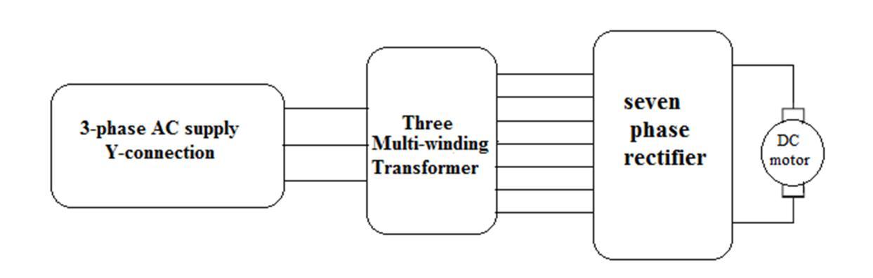
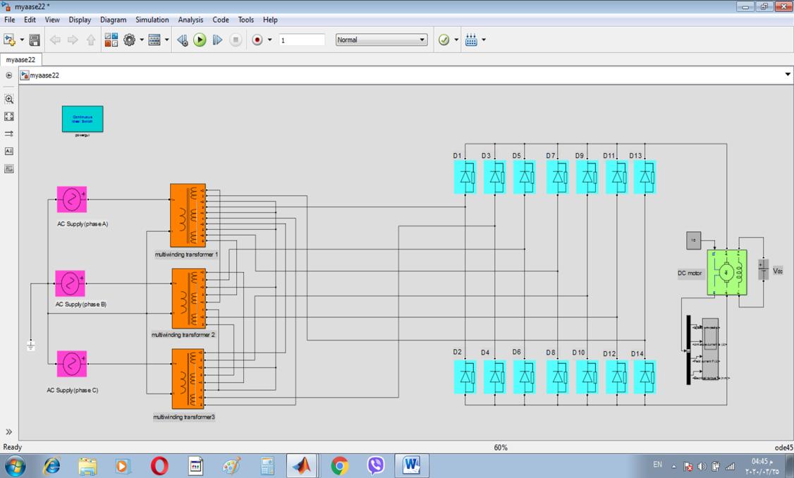
Fig (2) explains the block diagram for the suggested model in this paper. A three phase Y-connection is supplying a three multi-windingstransformers.Theoutputofthesetransformersrepresenttheinputofthesevenphaserectifier.TheDCmotor representstheloadoftherectifier.
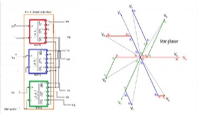
Figure (2) the block diagram of the suggested model
Any transformer having more than three phase (i.e.) multiphase have been focused by researchers due their importance. Where some applications needed multi-phase supply like: multiphase power transmission, five or higher phases rectifier systems,andvariablespeedmultiphasedrivesystem
Conventional generation units used three phase systems to supply customers, for obtaining multi-phase it needed to use transformerswithspecialstypeofconnection.
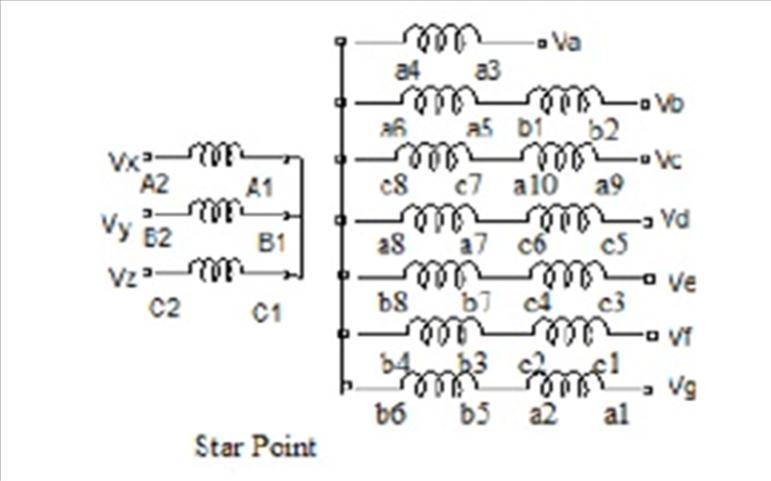
Therearethreecoresofirondesignedeachonerepresentsoneprimaryandfoursecondaryexceptonehavingfivesecondary windingsinsteadoffour.Therearesixterminalsinprimarysideconnectedinanaptwaytogetstarordeltaconnection.Atthe otherside(secondary)therearetwentysixterminalsconnectedinadifferentmannertogetastarorheptagonstyle Fig(3-a) showsthewayofconnectionoftransformerandfig(3-b)showsthearrangementofconnectionoftransformerwindingsinmat labSimulink.
Figure (3-a) proposed transformer winding ( star-star connection )


International Research Journal of Engineering and Technology (IRJET) e-ISSN: 2395-0056
Volume: 09 Issue: 08 | Aug 2022 www.irjet.net p-ISSN: 2395-0072
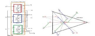
Figure (3-b) proposed transformer winding (star-delta connection)
The phase angle between the input waveform voltage is (2π/3) and output waveform has angle (2π/7). The choice of turn ratiodecidestherequisitephasedisplacementintheoutputphases.[1,2]
Thesevenphaseuncontrolledrectifierillustratesinfig.4
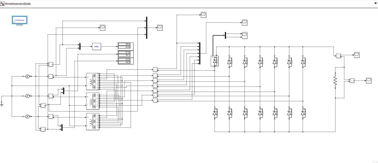
This rectifier consists of fourteen power diodes, where power electronics convertors fed by seven phase supply (three to sevenphasetransformer).Powerelectronicsdevises(D1–D7)operateatthepositivepartofthewaveandthedevises(D8–D14)operateattheotherpartofthewave.Thevoltageequationsofthesecondarytransformercanbewrittenas
Vpha1 = Vp sin (wt) (1)
Vpha2 = Vp sin (wt-2π/7) (2)
Vpha3 = Vp sin (wt-4π/7) (3)

International Research Journal of Engineering and Technology (IRJET) e-ISSN: 2395-0056
Volume: 09 Issue: 08 | Aug 2022 www.irjet.net p-ISSN: 2395-0072
Vpha4 = Vp sin (wt-6π/7) (4)
Vpha5 = Vp sin (wt-8π/7) (5)


Vpha6 = Vp sin (wt-10π/7) (6)
Vpha7 = Vp sin (wt-12π/7) (7)
Where Vp isthepeakvalueoftheinputphasevoltagetoneutralwithrespecttoneutral.
(1,2,3,4,5,6,and7)refereedtophasenumber [3,4]
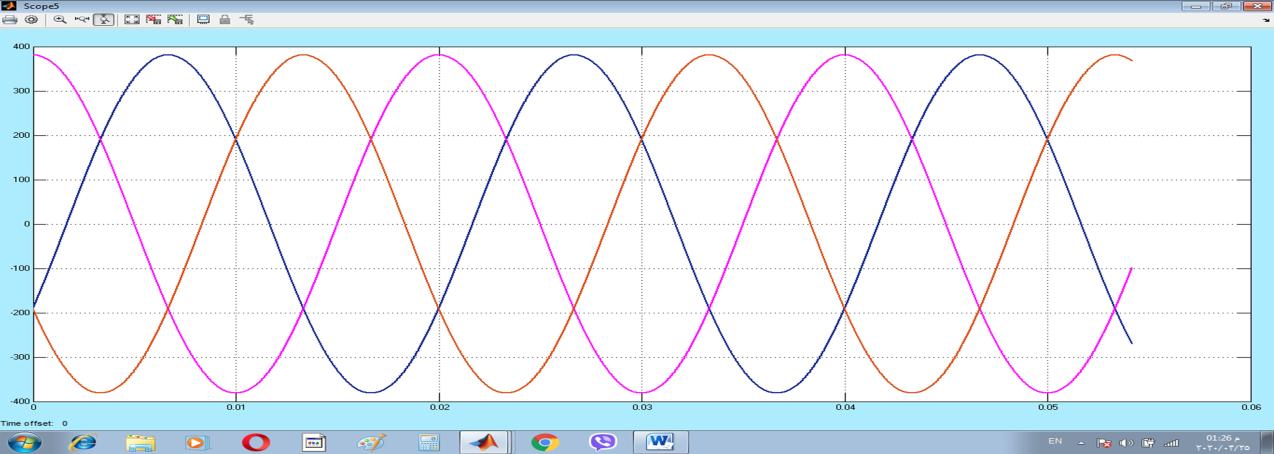
Fig(5)illustratesthewaveformsofthethreephaseinputvoltageswithrespecttoneutralpointtofedthreetransformer
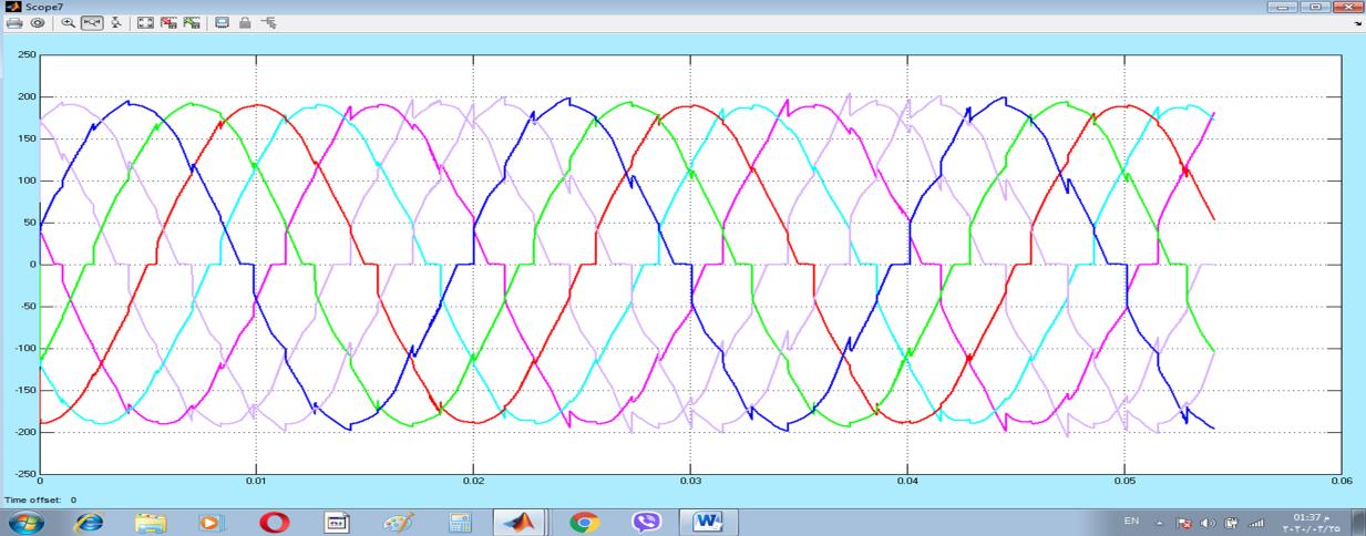
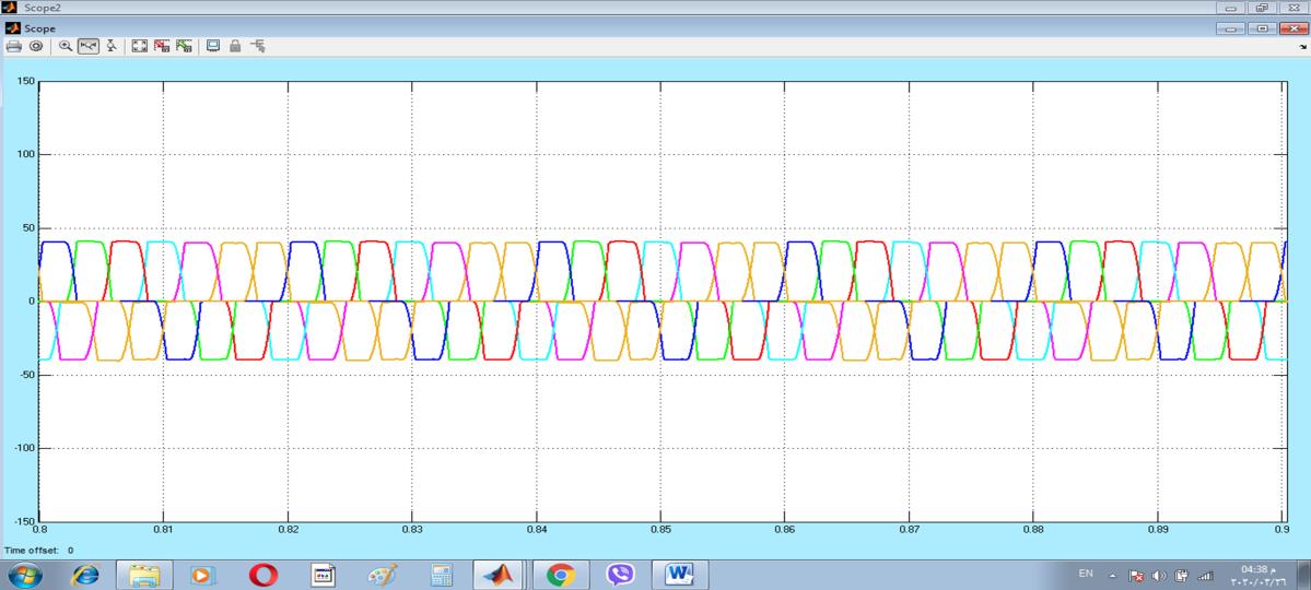
The aim of the special connection in fig (4) is to rise the number of the voltage phases from three to seven. These voltages represent the input of the seven phase rectifier. The waveforms of these voltages are distorted due to high reactance of the transformers.Fig(6)introducesthisphenomena
figure(6)
International Research Journal of Engineering and Technology (IRJET) e-ISSN: 2395-0056
Volume: 09 Issue: 08 | Aug 2022 www.irjet.net p-ISSN: 2395-0072
There are many types of load can be connected to rectifier circuit depending on their application. In this state a dc motor is connectedtoconverterasaloadwithspecificcharacteristictoobtaintheeffectonmulti-phaserectifierandnovelmethodfor convertingconventionalphasestomorethanitonitsperformance.Fig(7)showsthecompletecircuitofdriver .

Theproposedmodelwastestedwhentheloadofthemulti-phaserectifierwasDCmotor. Itcanbenoticethatthesimulation results representing all wave forms deals with driver witch show its performance under loaded circuit. it can be classify resultsintothreeparts:threephasepower supply,threetosevenphasemodifiedtransformer,anddcmotorasaload
6-1-Partone:supplyside
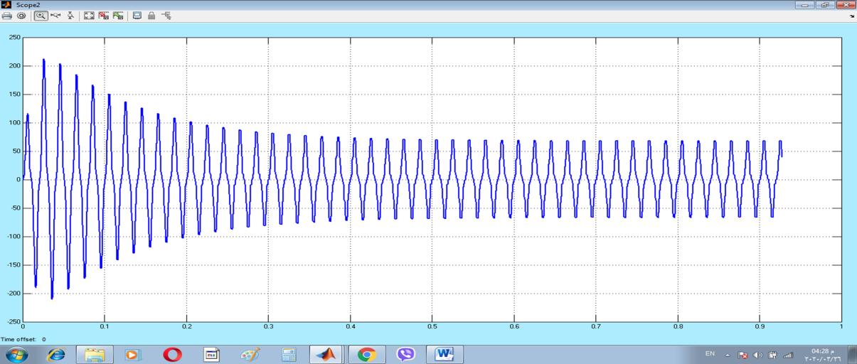
Figure(8)showsthewaveformofthecurrentinphaseA(oneofthethreesupplyphases).Fig(9)representsthewaveformsof outputcurrentsforthemulti-windings transformerwhichprovidethemulti-phaserectifier
International Research Journal of Engineering and Technology (IRJET) e-ISSN: 2395-0056
Volume: 09 Issue: 08 | Aug 2022 www.irjet.net p-ISSN: 2395-0072
Fig (8) represent current of source phase (A) on of three phase supply


Voltagewaveformofpowersupplyandtransformerareintroducedabove???
6-2-Parttwo:converterandpowerelectronicsdevice
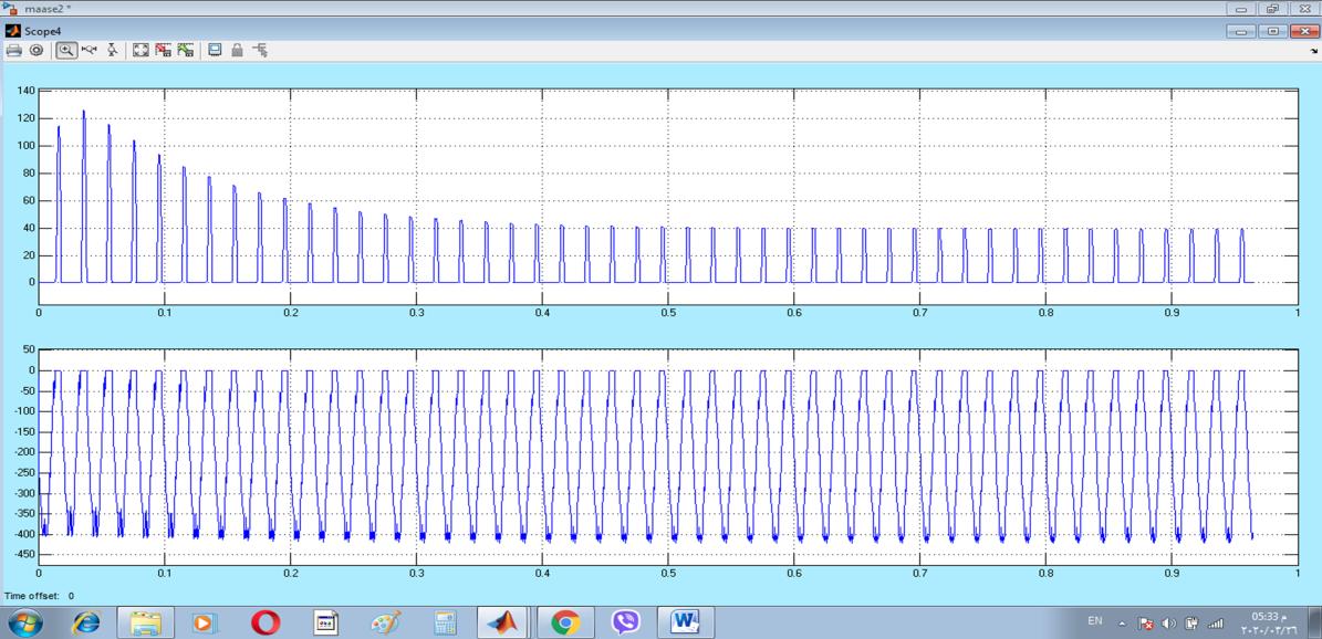
Figure (9) illustrates the waveforms of the current and peak inverse voltage for the diode, while figure (10) represents the waveformof outputvoltage forthe rectifierwhichrepresentstheloadvoltage.Figure(11)explains theoutput currentwave formoftherectifier(theloadcurrent).
International Research Journal of Engineering and Technology (IRJET) e-ISSN: 2395-0056
Volume: 09 Issue: 08 | Aug 2022 www.irjet.net p-ISSN: 2395-0072
fig(10)currentandpeakinversevoltagewaveformofdiode
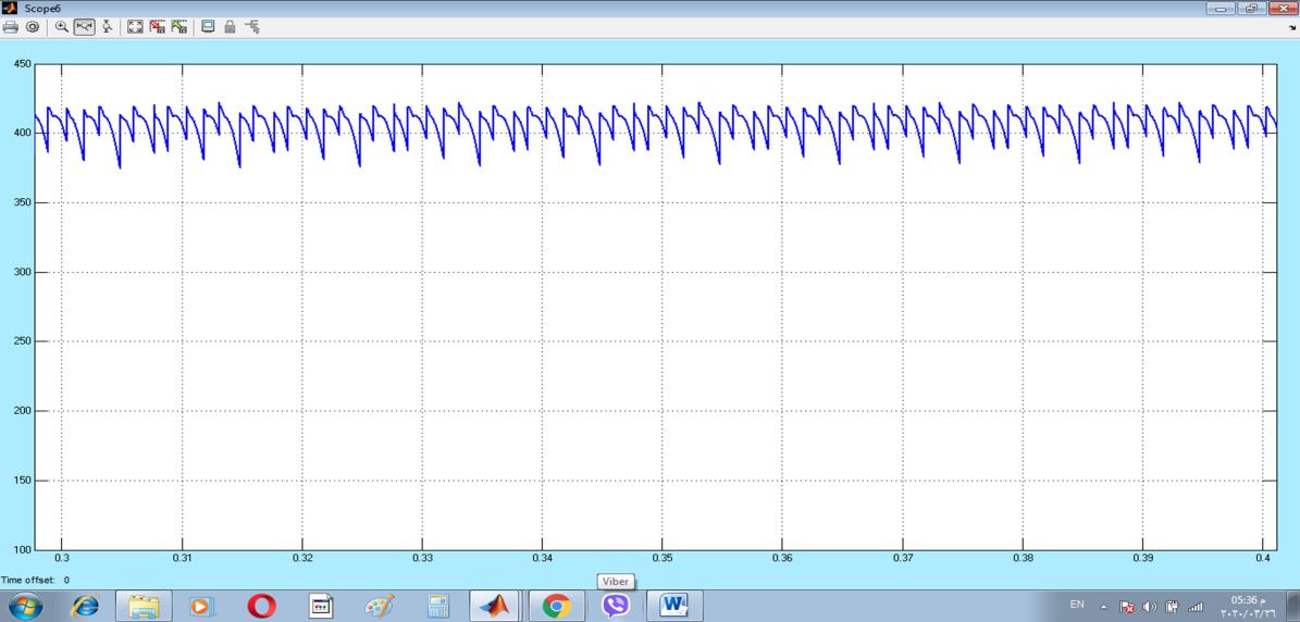
fig(11)outputvoltagewaveformoftherectifier

International Research Journal of Engineering and Technology (IRJET) e-ISSN: 2395-0056
Volume: 09 Issue: 08 | Aug 2022 www.irjet.net p-ISSN: 2395-0072
fig(12)outputcurrentwaveformofrectifiersupplyingload 6-3-partthreeloadside
Figure(13)showsthewaveformsforthe(speed,armaturecurrent,fieldcurrentandelectricaltorque)whichrepresentthe characteristicsfortheDCmotor.
Fig (13) Waveforms of (speed, armature current, field current and torque ) for the dc motor
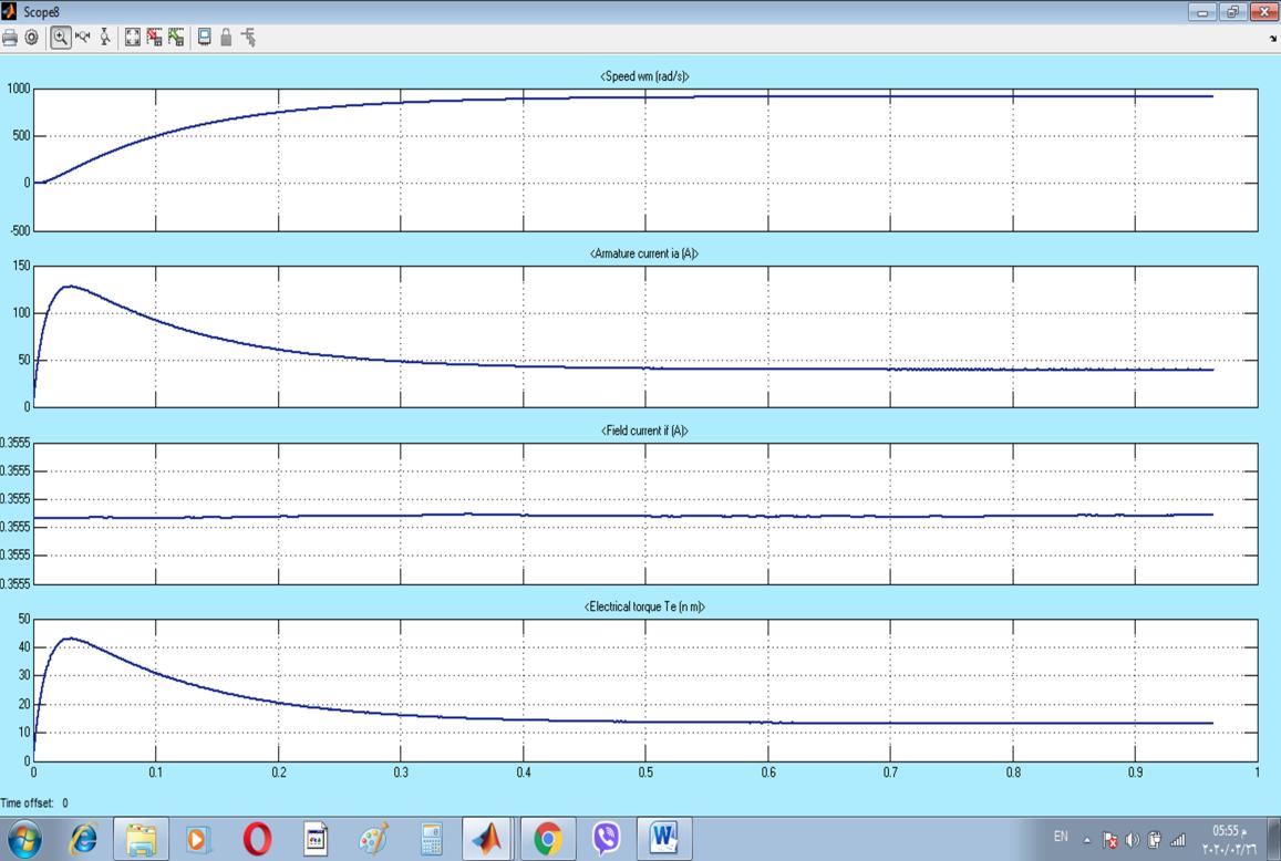

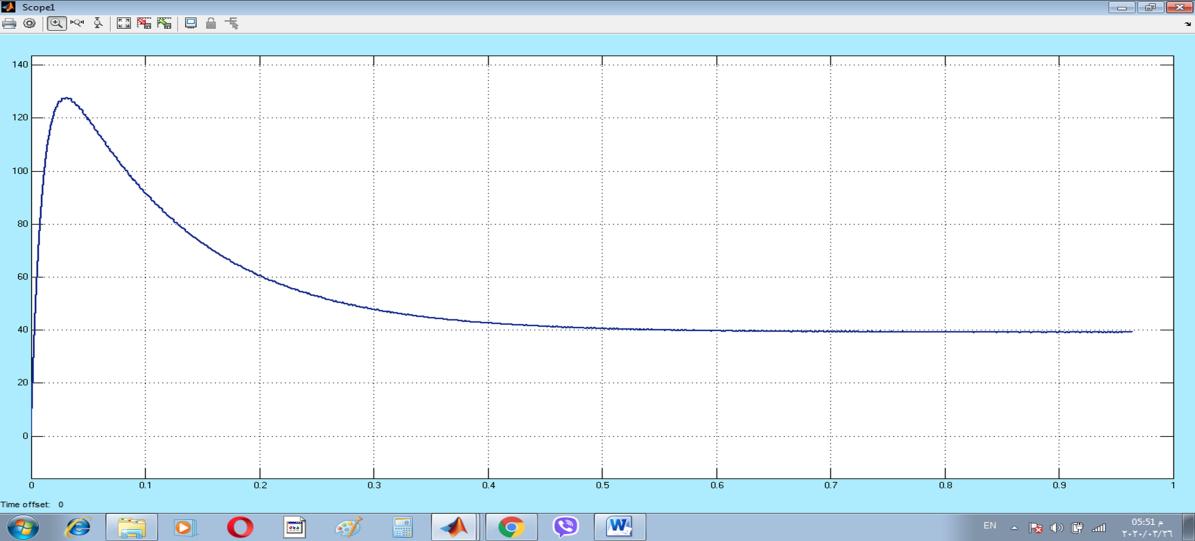
(a) (b) (c) (d)

International Research Journal of Engineering and Technology (IRJET) e-ISSN: 2395-0056
Volume: 09 Issue: 08 | Aug 2022 www.irjet.net p-ISSN: 2395-0072
Theadjacentlinevoltagecanbewrittenasfollow
Vdc=(7/π)∫ (8)
Vdc :dcvoltageofonephase
Idc=(7/π)∫ (9)
Idc(7):dccurrentofonephase
(7)
Theequationofthetotalharmonicsdistortion(THD)is:
THD%=√∑ / *100%
This paper introduced a novel seven phase rectifier with its analysis where a multi-phase system gets wide range of interesting in many application like wind energy system and sea marine, the results of circuit show the voltage and load current of resistive load where it can be notice good wave form for both voltage and currents for load and source sides also good total harmonics distortion compared with others circuits have phases less than proposed circuit. This circuit can be developedtowithotherapplicationtomakethemodernpowersystemmoreReliable.
1-ANovelThreePhasetoSevenPhaseConversionTechniqueUsingTransformerWindingConnections ,M.TabrezElectrical EngineeringDept.IndianInstituteofTechnologyChabad,India mdtabrez2008@gmail.comP.K.SadhuElectrical Engineering Dept. Indian Institute of Technology Dhanbad, India pradip_sadhu@yahoo.co.in A. Iqbal Electrical Engineering Dept. Qatar University Doha, Qatar atif.iqbal@qu.edu.qa , Engineering, Technology & Applied Science Research Vol. 7, No. 5, 2017, 19531961
2-GridSynchronizationofaSeven-PhaseWindElectricGeneratorUsingd-qPLL,KalaivaniChandramohan1,Sanjeevikumar Padmanaban 2,* , Rajambal Kalyanasundaram 1 , Mahajan Sagar Bhaskar 2 and Lucian Mihet-Popa 3 www.mdpi.com/journal/energies
3- Contribution à l’étude d’une chaîne de conversion d’énergie AC-DC / DC-DC ,tolérante aux défauts MSAP pentaphasée –redresseuràdiodes–Boostsentrelacés
4-ChapterFive-PhaseLineCommutatedRectifiers.MahmoudI.Masoud