International Research Journal of Engineering and Technology (IRJET) e-ISSN: 2395-0056

Volume: 09 Issue: 08 | Aug 2022 www.irjet.net p-ISSN: 2395-0072
International Research Journal of Engineering and Technology (IRJET) e-ISSN: 2395-0056
Volume: 09 Issue: 08 | Aug 2022 www.irjet.net p-ISSN: 2395-0072
1,2,3,4Dept of mechanical engineering, Rao Bahadur Y. Mahabaleswarappa engineering college Ballari-583104, Karnataka, India ***
Abstract - An Investigation project done with the objective to analyse the emission and performance of single cylinder four stroke diesel engine at different load conditions .In this project inlet air manifold is modified using swirl enhancer to generate the swirl of air so that efficient combustion is achieved This experiment is done aiming to improve thermal efficiency and decrease harmful emissions by maximizing the use of air fuel during the combustion process .
Key Words: Diesel engine, Swirl enhancer, Performance, Emissions, Combustion process
In todays world pollution is the major problem caused by emissions of harmful gases from different sources like automobiles and industries which pollutes the environment. The harmful gases may be CO,HC,CO2 and NOx etc. NOx emissions are greatly reduced by generating swirling air. Swirling air causes rapid mixing of fuel and air. Swirl is the ordered rotation of air entering the engine cylinder. Swirl can be generated in different ways, in our experent it is generatedusingswirlenhancerinstalledininletairmanifold.


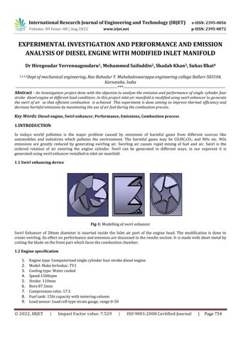
Fig-1: Modellingofswirlenhancer
Swirl Enhancer of 28mm diameter is inserted inside the Inlet air port of the engine head. The modification is done to createswirling.Itseffectonperformanceandemissionarediscussedintheresultssection.It ismadewithsheetmetalby cuttingthebladeonthefrontpartwhichfacesthecombustionchamber.

International Research Journal of Engineering and Technology (IRJET) e-ISSN: 2395-0056
Volume: 09 Issue: 08 | Aug 2022 www.irjet.net p-ISSN: 2395-0072
10. Loadindicator:Digital,Range0-50kg
11. Rotameter:Caloriemetercooling25-250LPH;Engine40-400LPH.
1. Sheetmetalisusedformakingswirlboosterasitisdeformableinnature.
2. Itcan easilytaketheshapeof theinletairport.
3. Sheeetmetaloperationsrequirelessequipmentsandareeasierthanmachining.
Swirl enhancer(Physical model)
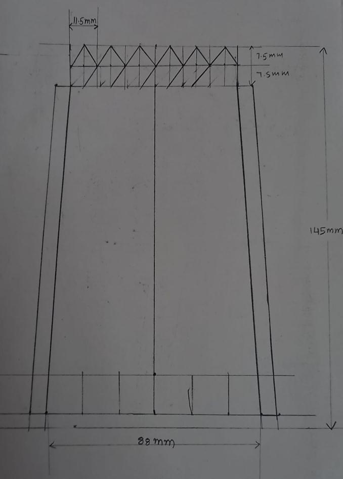
Fig-2: Sideviewoftheswirlenhancer
Fig-3: Topviewoftheswirlenhancer
1. A 15x15mmsteelsheetmetalisselectedformakingtaperedswirlenhancer.

2. Asheetmetalisselectedbecauseitiseasytoperformoperationswhilemakingaswirlenhancer.
3. Sheetmetalworkingtoolsareusedformakingswirlenhancer.
4. AswirlenhancermadeupofsheetmetalcaneasilytaketheshapeoftheInletairport.
5. Initiallyadevelopmentofconemethodisusedtodrawthedevelopmentof taperedswirlenhancer.
6. Thedevelopmentispastedonsheetmetalandcuttedaccordingly
7. Thecuttedsheetmetalisrolledtoformataperedswirlbooster
8. Theswirlenhancerisinsertedinsidetheinletairportofthecylinderhead.
International Research Journal of Engineering and Technology (IRJET) e-ISSN: 2395-0056
Volume: 09 Issue: 08 | Aug 2022 www.irjet.net p-ISSN: 2395-0072
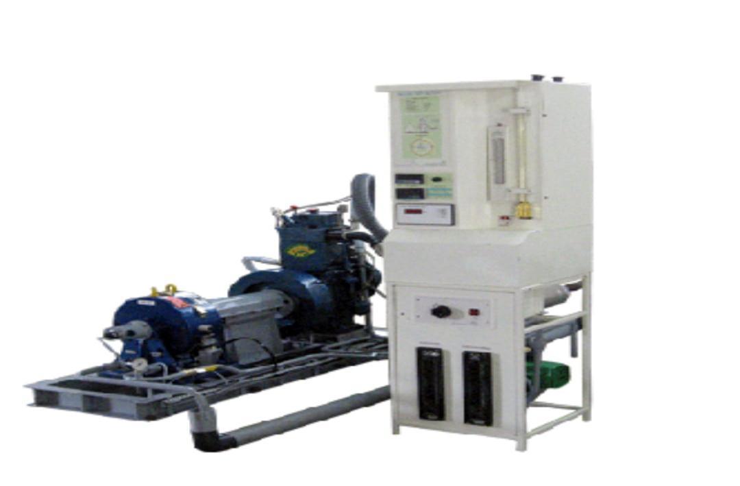
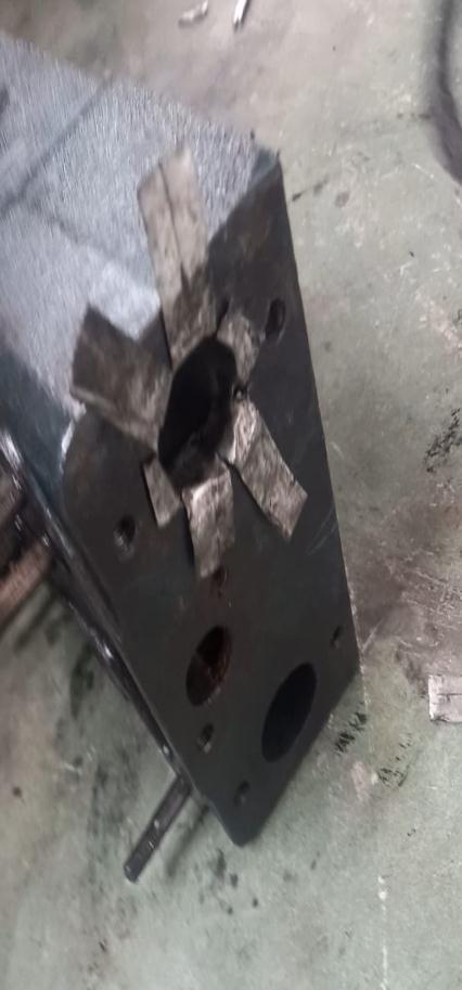
Fig-4: Devlopmentsketchofswirlenhancer Fig-5: Swirlenhancerinsertedinacylinderhead 3. EXPERIMENTAL SETUP
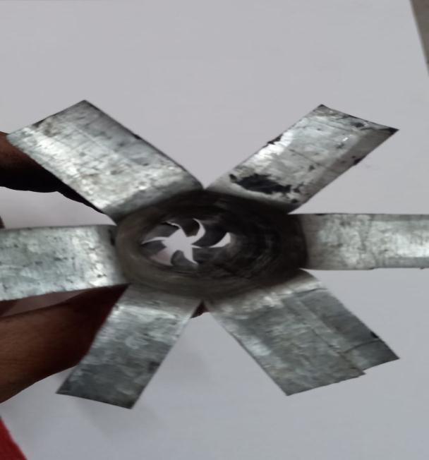
Fig-6: Computeriseddieselenginetestrig
International Research Journal of Engineering and Technology (IRJET) e-ISSN: 2395-0056
Volume: 09 Issue: 08 | Aug 2022 www.irjet.net p-ISSN: 2395-0072
Testrigconsistsof 1. Singlecylinderfourstrokedieselengine(computerised). 2. Fueltankandfuelmeasuringunit. 3. Rotametersforcoolingmeasurement. 4. Transmittersforfuelflowandairflowmeasurementnts. 5. Eddycurrentdynamometerforloading 6. Emissiontestingequipment.
1. Initiallyengineisfueledwithdiesel. 2. Engineischeckedforcoolingwaterflow. 3. Ensuringitisat0kgload. 4. Ensurepowersupplymainsareon. 5. Ensureenginetestrigisconnectedcomputerandemissioncheckingdevice 6. Starttheenginewith0kgloadandrunfor20minutesand slowlyrisetheload 7. Loadisincreasedby2kg,4kg.6kg,8kgand12kgandreadingsaretabulated
1. Load vs Brake thermal efficiency
20.00
15.00
10.00
5.00
BTHE in % Load in Kg
25.00 0 2 4 6 8 12
BTHE 1(%) BTHE 2(%)
0.00
Chart-1: LoadvsBrakethermalefficiency
Brake thermal efficiency depends on Brake power and specific fuel consumption. Here Specific fuel consumption is increasinginanenginewithmodifiedinletmanifoldastheflowoffuelismorethanair.Hencebrakethermalefficiencyis increasingwithincreasingloadBrakethermal efficiencyof anenginewithanmodified inetmanifoldisslightylessthan conventionadieselengine
International Research Journal of Engineering and Technology (IRJET) e-ISSN: 2395-0056
Volume: 09 Issue: 08 | Aug 2022 www.irjet.net p-ISSN: 2395-0072
2. Load vs Specific fuel consumption
SFC in Kg/kWh
0 0.2 0.4 0.6 0.8 1 1.2 1.4 0 2 4 6 8 12
Load in kg
Chart-2:LoadvsSFC
Thespecificfuelconsumptionofconventionaldieselengineislowerthanthatofenginewithmodifiedinletmanifold.This isbecauseofthedisturbedairpassageintheairinletport.
3. Load vs Indicated thermal efficiency
100
80
60
40
120 0 2 4 6 8 12
ITHE in % Load in Kg
20
ITHE 1(%)
ITHE 2(%)
SFC 1 SFC 2 0
Chart-3: LoadvsITHE
Indicated thermal efficiency depends on the indicated power which inturn depends on the indicated mean effective pressure.Indicated mean effective pressure is the average pressure in the cylinder for a complete engine cycle. As indicated mean effective pressure is increasing for diesel engine with modified inlet manifold .The ITHE of diesel engine withmodifiedinetmanifoldhasslightyhigherthanconventionadieseengine.
International Research Journal of Engineering and Technology (IRJET) e-ISSN: 2395-0056
Volume: 09 Issue: 08 | Aug 2022 www.irjet.net p-ISSN: 2395-0072
4. Load vs Mechanical efficiency
50
40
A/F Ratio
70
60
50
40
30
20
10
30
20
60 0 2 4 6 8 12
mech eff in % Load in Kg
10
0
Chart-4: LoadvsMechanicalefficiency
Mechanicalefficiencyisobtainedbytheratioofbrakepowertotheindicatedpower.Astheindicatedpowerisincreasing inanenginewithmodifiedinletmanifoldhencemechanicalefficienyisdecreasing
5. Load vs A/F Ratio
80 0 2 4 6 8 12
Mech eff 1 Mech eff 2 Mech eff 3 Mech eff 4 0
Load in Kg
Chart-5: LoadvsA/FRatio
Conventional Modified inet manifold
Theairfuelratioismoreinconventionaldieselengineanditisreducinginanenginewithmodifiedinletmanifoldbecause oflessairflowresultinginrichmixture.
International Research Journal of Engineering and Technology (IRJET) e-ISSN: 2395-0056
Volume: 09 Issue: 08 | Aug 2022 www.irjet.net p-ISSN: 2395-0072
1. Load vs CO emission
0 0.5 1 1.5 2 2.5 3 3.5 4
CO in % Load in Kg
Conventional diesel engine
2. Load vs HC emission
160
140
120
100
80
60
40
20
0kg 2kg 4kg 6kg 8kg 12kg
Chart-6: LoadvsCOemission
HC in PPM Load in Kg
Modified inlet manifold with diesel 0
0kg 2kg 4kg 6kg 8kg 12kg
Chart-7: LoadvsHCemission
Conventional diesel engine Modified inlet manifold with diesel
Higher fuel/air ratio causes the emission of HC and CO. During the initial loads the CO and HC emissions are comparativelysmallandthereisslightdifferencebetweendifferencebetweenthetwoButathigherloadsitisincreasing becausewithincreaseintheloadthefuel/airratioincreasesandalsothereisdisturbanceforairflowduetomodification ifaninletmanifold.Thiscausesrichfuel/airmixturehenceresultinginCarbonmonoxideandhydrocarbonemissions.
International Research Journal of Engineering and Technology (IRJET) e-ISSN: 2395-0056
Volume: 09 Issue: 08 | Aug 2022 www.irjet.net p-ISSN: 2395-0072
3. Load vs CO2 emission
0 1 2 3 4 5 6 7 8 9
CO 2 in % Load in Kg
Conventional diesel engine
0kg 2kg 4kg 6kg 8kg 12kg
Chart-8: LoadvsCO2 emissions
Thecombustionprocesscausesamixingofcarbonwithoxygeninairresultingintheformationofcarbondioxide.The changeofCO2emissionisslightyreducedinanenginewithmodifiedinletmanifoldatmaximumload.
4. Load vs NOx emission
NOx in PPM Load in Kg
Conventional diesel engine
Modified inlet manifold with diesel
Modified inlet manifold with diesel 0 100 200 300 400 500 600 700 800 0kg 2kg 4kg 6kg 8kg 12kg
Chart-9: LoadvsNOxemission
NOx emissions increases with increase in load because it causes increased fuel supply resulting in longer combustion durationcausingincreasein temperaturehenceitcausesNOxformation.TheNOxemissionsare decreasinginanengine withmodifiedinletmanifoldbecauseofrichmixtureburning.
International Research Journal of Engineering and Technology (IRJET) e-ISSN: 2395-0056
Volume: 09 Issue: 08 | Aug 2022 www.irjet.net p-ISSN: 2395-0072
5. Load vs O2 emission
0 2 4 6 8 10 12 14 16 18 20 0 2 4 6 8 12
O2 in % Load in Kg
Conventional diesel engine
Chart-10: LoadvsO2 emission
WithincreasingloadoxygenemissionisreducingindifferentsetupswhichresultsingoodcombustionoffuelO2emission isalsonearlysamefordifferentsetupsandfuels.
6. Load vs smoke emission
50
40
30
20
60 0 2 4 6 8 12
Smoke in PPM load in Kg
10
Conventional diesel engine
Modified inlet manifold with diesel
Modified inlet manifold with diesel 0
Chart-11: LoadvsSmokeemission
Smoke emission is the part of combustion process.Smoke is increasing with increasing load because of rich fuel mixture burning
1. Inletairswirliscreatedbyusingmodifiedinletmanifold.
2. It concludes that small reduction in Brake thermal efficiency and sight increase in specific fuel consumption.
International Research Journal of Engineering and Technology (IRJET) e-ISSN: 2395-0056
Volume: 09 Issue: 08 | Aug 2022 www.irjet.net p-ISSN: 2395-0072
3. Carbonmonoxideandhydrocarbonemissionsareslightydecreasingatthe initialloadsandincreasingat thehigherloadsduetorichmixture.
4. Nitrogenoxide,carbondioxideandoxygenaredecresinginanenginewithmodifiedinletmanifold.
1. T. Shimadev, K.Sakai and S Kurihara, Variable swirl inlet and its effect on diesel engine performance and emissions SAEVol 95,section4(1986).
2. Himegoudar Yerranna Goudaru & Shiva Prasad Desai. Effect of intake air swirl on single cylinder four stroke dieselengineperformance.Vol11,Version iv(July-August2014).
3. Vinod Kumar Sharma, Man Mohan and Chandra Mouli, Effect of inlet swirl on performance of single cylinder directinjectiondieselengine.2017IOPConf.
4. Mahmut KAPLAN, Influence of swirl tumble and squish flows on combustion characterstics and emissions in in ternulcombustionengine–Review .
5. InternalcombustionenginesbyVganesan4th edition.
6. InternalcombustionenginesfundamentalsbyJohnBHeywood.