International Research Journal of Engineering and Technology (IRJET) e-ISSN: 2395-0056

Volume: 09 Issue: 08 | Aug 2022 www.irjet.net p-ISSN: 2395-0072
International Research Journal of Engineering and Technology (IRJET) e-ISSN: 2395-0056
Volume: 09 Issue: 08 | Aug 2022 www.irjet.net p-ISSN: 2395-0072
1M.Tech. Student, Department of Civil Engineering, Pacific Academy Of Higher Education And Research University, Udaipur, Rajasthan, India 2,Assistant Professor, Department of Civil Engineering, Pacific Academy Of Higher Education And Research University, Udaipur, Rajasthan, India ***
Abstract:- Communication tower are used for transferring the signals. They are used by various mobile companies as well as for transferring the electricity or for power transmission. Recently various studies have been done on design of Telecommunication Towers, but in most studies the researchers have considered the effect of wind and seismic forces on the four legged self-supporting towers. However, no researches have provided the measure to overcome the effects of varying loading condition with different material. In this study, will be focusing on study of wind force on tower made of high steel tower with Lattice Steel Masts. In this study the mobile tower was developed using auto cad software. This 3D cad model developed was further imported into the ANSYS software where the model was subjected to the wind loads with the aid of different propositions used for development of the structure and further the structure was characterized using the software into smaller components. 3D solid elements were used for the development of the meshed model. This model was also subjected to different forms of material models in order to obtain an optimized structure. Material models of linear material properties were imported into the model and the contacts were defined as linear non separable structures so that the mobile structure behaves as a single structure and the load bearing capacity of the structure can be evaluated. The mobile tower is developed using different complex cross-sectional section cross bars/ties in order to maintain the connection between critical load carrying members and further they were connected in such a way the load transferred properly and each cross-member remains under safe condition with respect to maximum loads. In this case, the mobile tower is fixed at the bottom of the base with all degree of freedom as zero (means constant). After that the wind loads (taken from the reference paper) is applied on the structure to obtain the performance of the structure with respect to the loads. Further different forms of loads are applied on the structures and the structure is also varied with respect to enhancement in the thickness of the slabs used for developing the mobile structure in order to optimize the
structure with respect to varying loading conditions. Taguchi method and ANOVA technique were used to optimize the results obtained in FEM analysis. In this study it was obtained that if the height increases then X bracing proves uneconomical and K bracing proves economical. Similarly, Magnitude of displacement in tower of smaller size is lower with same thickness on action of same intensity blast loads. Moreover, Magnitude of stresses in tower of smaller size is lower with same thickness on action of same intensity blast loads.
Keywords: Mobile tower, ANSYS, Optimization, Varying wind/axial loads
India already has over 750,000 cell phone towers and, accordingtoestimates,willhavemorethanquadruplethat number by 2025, making it one of the fastest expanding telecommunication markets in the world. Telecommunication towers are tall structures that are typically used to support parabolic antennas that are utilized for microwave communication. They're also used to deliver radio and television signals to far-flung locations, and they're set up at a specified height. Selfsupporting structures are classified as three-legged and four-legged space trussed structures. Self-supporting towers usually have a square or triangular design and are supportedonthegroundoronbuildings.Whencompared tosquaretowers,triangulartowersgeneratesmallerwind loads.[1].
Nonetheless,theyareutilizedexclusivelyformore modest levels of pinnacle because of hardships in joint itemizing and manufacture utilizing point segments. Nowadays there is a phenomenal ascent in the number of cross section towers because of a steadily expanding request in correspondence. Cross section towers are 3D space approaches that for configuration are customarily
International Research Journal of Engineering and Technology (IRJET) e-ISSN: 2395-0056
Volume: 09 Issue: 08 | Aug 2022 www.irjet.net p-ISSN: 2395-0072
broke down as 2D supports. For security and economy, theseplansshouldbeallthemorethoroughlyinvestigated thinking about them as 3D edges. Media transmission pinnacles or cross section towers are arranged into three classifications that are Guyed poles, monopole and selfsupportingpinnacles[2].
They function primarily as cantilever brackets and are designed to transport wind load as the primary source of natural burdens. Tremor-induced loads are generally ignored in plans, with the exception of basic designs used in high seismic-risk areas. The main cause of telecom tower failures throughout the world is concentrated energy winds, but there are still aspects to be targeted (HIW). The main issue is that estimating wind loads is challenging because it is based on a probabilistic technique. Several studies of telecommunication towers have been conducted, taking into account both the wind and seismic effects. The wind was used as the major force in the investigation, and the joint displacements were calculatedusingtheGustfactormethod.
Wind was taken as the main force for analysis and using the method of wind coefficient, joint displacement, chi forceandpeakstresswerecomparedtofindouttheeffect of difference in modeling strategy on force. design impact on truss. communication tower [3]. These towers require more steel but cover less base area, making them suitable for many situations. The availability of land, which meets the ideal conditions for transplanting in an urban environment, is very limited and there is no other option but to adopt roof towers with marginal adjustment in position but no right in height. This fact is mainly due to the fact that telecommunications towers built on the ground have performed well in previous earthquakes. However, roof-mounted towers respond to horizontal movementdifferentlythanthosebuiltonfirmground..
Communication towers are usually designed as a 3D truss, which is not an actual representation of the structure. In traditional stress calculations based on the analysis of linear elastic ideal trusses, the members are assumed to be concentrically loaded and connected by dowels.
Current requirements for large structures and road structures, such as bridges, are increasingly stringent, requiringlargerelementsthatmakethemmoreexpensive [1]. On the other hand, the current trend of large-scale project construction has made steel structure a major construction alternative [2]. However, reducing the amountofmaterialinthemanufactureofsteelelementsto
make them lighter also makes them slimmer. This condition can affect the stability of the structure by possibly triggering local or global warping failures, in practicethisis moresevere whenthestructureisina fire condition. [5]. Developments in the field of structural optimizationbeganaroundthesametimeasFEM.
Inthelastdecade,thetelecommunicationindustry has radically changed from conventional operations and systems to data-driven applications, while its further evolution is a necessity in order to meet the new technologies of emerging smart home and smart city concepts. The telecommunications business has evolved dramatically in the previous decade, moving from traditional operations and systems to data-driven applications, and additional transformation is required to match the new technologies of upcoming smart home and smart city concepts. Given the growing demand for services in cities as a result of population growth, the necessityformoresupportstructurestobebuiltinsidethe urban framework is obvious. Existing telecommunication towers,ontheotherhand,maynothavebeenintendedto cope with such higher gravitational and lateral forces, resulting in a greater risk of overloading and damage, which could even lead to the collapse of such slender buildingsduetothenewloadingframework.Furthermore, because these flexible constructions are subjected to fluctuating loads induced by dynamic wind effects on a constant schedule, fatigue damage is highly likely. As a consequence, exhaustion telecommunications masts and towerswouldneedtobereplaced[53].
Communication tower are used for transferring the signals.Theyareusedbyvariousmobilecompaniesas well as for transferring the electricity or for power transmission.
I. Tomodelthestructureofmobiletower.
II. To analyze this structure by varying the different
loadingconditions.
III. To optimize the loading parameter for enhancementofstructurewithdifferentmaterials.
International Research Journal of Engineering and Technology (IRJET) e-ISSN: 2395-0056
Volume: 09 Issue: 08 | Aug 2022 www.irjet.net p-ISSN: 2395-0072
In most of the recent studies as per the literature it was observed that more emphasis was given on the design of different types of telecommunication towers but theeffectsofwindsandseismicloadsonthestructurewith different forms of varieties as well as the optimization of the results in order to predict the best behaviour of the mobile tower structure. Furthermore, no researches have provided the measure to overcome the effects of varying loadingconditionwithdifferentmaterial.Inthisstudy,will be focusing on study of wind force on tower made of high steeltowerwithLatticeSteelMasts


This thesis is divided into seven chapters. An overview of thesechaptersispresentedbelow.
Chapter1
This is an introductory chapter which elucidates problem statement, objective, research methodology and organizationofthethesis.
Chapter2
This chapter deals with the literature survey for the presented work and examined a comprehensive background of other related research works contributed by many research papers and other referred journals related to the present work with recent research work goingonworldwideandhasassuredtheconsistencyofthe workperformed.
Chapter3
This chapter deals with modelling of pile design analysis using Solidworks. This chapter contain design parametersforblastinganalysis.
Chapter4
This chapter deals with blast analysis using ansys orLSDynasoftware.Inthischapterthestructuremadeby considering the different dimension and material is analysedbyvaryingdifferentoperatingparameters.
Chapter5
This chapter deals with optimization of different operatinganddimensionalparameterstogettheoptimum result.Thischapterdealswiththedetailanalysisofdesign ofexperimentsusingTaguchimethod.
Asakeypartofhighvoltagepowertransmission,thelong span power transmission tower-line system is considered asthelifelineprojectinpowerengineering.Duetoitslarge height-to-width ratio, latticed steel power transmission tower (except for 4-leg classical lattice towers of normal height)exhibitsrelativelylowflexiblebendingstiffness.As commonnaturalphenomena,iceandsnowarethreatening the operation of long span power transmission tower-line system, due to their accretion feature. The damages or failures occurring at the power transmission tower-line system due to ice or snow loads mainly involve three reasons[2]:(1)Overloadingwhichisduetotheincreaseof
International Research Journal of Engineering and Technology (IRJET) e-ISSN: 2395-0056
Volume: 09 Issue: 08 | Aug 2022 www.irjet.net p-ISSN: 2395-0072
weight and windward area; (2) Unevenly ice-accretion or ice-shedding which would result in the damage of structural member; (3) Transmission line galloping which would result in the inclination or collapse of the whole tower. Based on the climatic conditions, additional considerationshouldbetakenintoaccountinthedesignof power transmission tower-line system, especially for the progressive collapse analysis of power transmission tower-linesystem.
Jithesh Rajasekharan et al. (2014) designed the lattice tower for three heights of 30m, 40m and 50m with different typesofbracingstostudythe effect of windload on 4- legged lattice tower for wind zone V and VI using gustfactormethod.Theyalsostudiedtheseismiceffecton the tower structures by carrying out the modal analysis and response spectrum analysis for zone II to zone V and concluded that the member stresses in bottom leg of XX braced tower are higher as compared to other tower models.
Siddesha. H (2010) presented the analysis of microwave antenna tower with Static and Gust factor method and compared the towers with angle and square hollow sections. The displacement at the top of the tower was considered as the main parameter. The towers with different configuration have also been analysed by removing one member present in the regular tower in lower panels. Square sections were found to be most effectiveforlegsascomparedtotheanglesections.
A. Jesumi.et al. (2013)modelled five steel lattice towers with different bracing configurations such as the X-B, single diagonal, X-X, K and Y bracings for a given range of height.Theheightsofthetowersare40mand50mwitha basewidthof2mand5mrespectively.Thetowerofheight 40m has 13 panels and the tower of height 50m has 16 panels. 70-72% of the height is provided for the tapered partand28-30%of theheightis providedfor the straight partofthetower.Thetowershavebeenanalyzedforwind loadswithSTAADPro.V8i,tocomparethemaximumjoint displacement of each tower. Optimized design has been carriedouttoestimateand tocomparethe weightof each tower.Fromtheresultsobtained,Ybracinghasbeenfound tobethemosteconomicalbracingsystemuptoaheightof 50m.
Konno et al. (1973) presented the effects of earthquake loads on lattice telecommunication towers atop buildings and obtained the mode shapes, the natural frequencies, andthedampingpropertiesofsuchstructures.Simulation of a stick model of the tower using lumped masses and a
viscousdampingratioof1%wasusedintheirstudiesand observed that in some of the members, the forces due to earthquakeweregreaterthanthoseduetowind.
Bhatt et al. (2013) analysedtwolatticetowersofheights 18m and 40m by modelling them by three different structural idealizations namely, as 3D frame, 3D truss and as a hybrid of the two.It was found that the truss model gives representative values of axial forces /stresses in all members. However, the truss models underestimate the bending stresses because only the effect of out of plane bending has been considered in it. Either of the frame model or the hybrid model may be used for estimates of combinedstressesforcheckingthedesign.Inthisstudy,it was found that the combined stresses necessitated the redesignofbasemembers.
J.G.S. da Silva et al [3] carried out the Structural Assessment of current steel design models for guyed steel telecommunication towers for radio antenna by the finite element method in ANSYS using three different structural idealizations of the model. They recommended the adoption of the model with bracings made of truss elements.SullinsEricJames[11]onthe
basisofthestudy offreestandingKansasCitytower(used as radio communication tower) analyzed using the ERITowersoftwareforwindandiceeffectsconcludedthat diagonalbracingtendstocontroltheabilityofthetowerto withstandwindandiceloadings.
W.Q. Jiang [9] showed that accurate prediction of the structuralcapacityoflatticetowersunderdifferentfailure modes is very important for accurate assessment of the reliability of transmission lines and power grids, and for designofefficientfailurecontainmentmeasures.
Thefull-scaletransmissionlatticetowertestsshowedthat the analysis results grossly underestimate the measured deflections, which might be as large as three times the theoreticallinearelasticdeflections.
Al-Hussein et al. [9] conducted a study that explored an approach to complement simulation with visualization. It reduces difficulties stemming from lack of proficiency in generating detailed simulations, a skill that engineers are nottypicallytrainedfor.Theyclaimedthattheintegration of a 3D model and lifting event simulations is helpful in validatingliftingplans.However,usersofthissystemhave to rely on visuals to identify the conflicts associated with eachsimulatedevent.
International Research Journal of Engineering and Technology (IRJET) e-ISSN: 2395-0056
Volume: 09 Issue: 08 | Aug 2022 www.irjet.net p-ISSN: 2395-0072
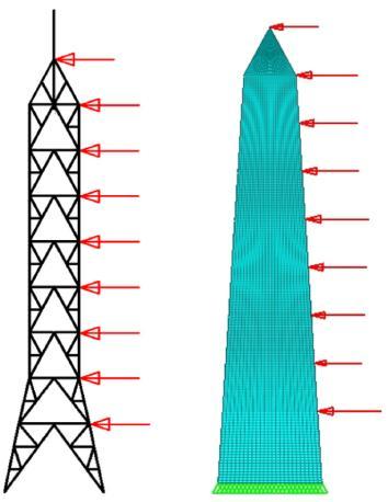
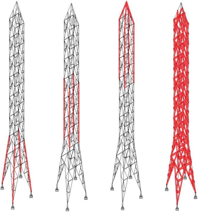
Alldesigndomainscreatedarebasedonthegeometryofa steel lattice self-supported tower located in Greece designedtoresistwindaswellasseismicactions(Fig.2.3).
The19mheightfour-leggedloomfeaturessquareonplan configuration, partially-tapered vertical profile and triangular shaped tip to allow antenna fitting. This structure represents a conventional geometry for lattice telecommunication towers and will be referred in this worktoasoriginaltowerUA.Three2Ddistinctgeometries were formed, all based on the perimeterlines of the tower UA; (i) a fully-tapered (FT), (ii) a fully-straight (FS), and (iii) a partially-tapered (PT) (Fig.2.3). The analysis of the domain to produce the most consistent and realistic outcomes shall be considered in the creation of the novel skeleton.
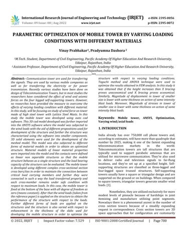
highermagnitude of distributed load, it has improved the outcome of theanalyses by providing coherent and ideal topologylayouts.
Fig. 2.1 Initial loading scenario used for the OA.
BasedonFig.3,thereductionoftheelementthicknessand volume fraction constraint improved the clarity of the solution with fewer core elements replacing smaller and thinner dense elements (i.e., struts and ties). Analysis C clearly indicated the stress paths required by a single tower face to withstand the loading scenario presented in Fig. 7. In addition, it is confirmed that the final output is dependent on the specified loading scenario and support conditions.
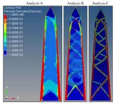
Fig.2.1.Developing the 2D domains based on the geometry UA.
Moreover, as for the boundary conditions, it is assumed thatthefullbasewidthofthe2Ddesigneddomainsisfixed duringtheoptimisationstudies.Thisistoidentifytheexact location of stress paths generatedwithin the domain, and hence estimate the number and location ofcolumns required in a single tower face. Providing fixities only at thebase corners would force the analysis to distribute the material from thetop to the bottom two fixities of the domain, and therefore, potentiallylimit the number of columns. On the other hand, to reduce the computationaltime of the 3D domain OA and provide a morecoherentresult,fixitiesareprovidedonlyatthebase corners.Furthermore, the initial analyses are performed considering pointloads applied only at the top and at the locations of secondary horizontalbracing members as currently used in the topology of UA model (Fig. 2.2). It is noticed that by altering the loading scenario to a
Fig. 2.3 progressively improving OA output by altering parameters
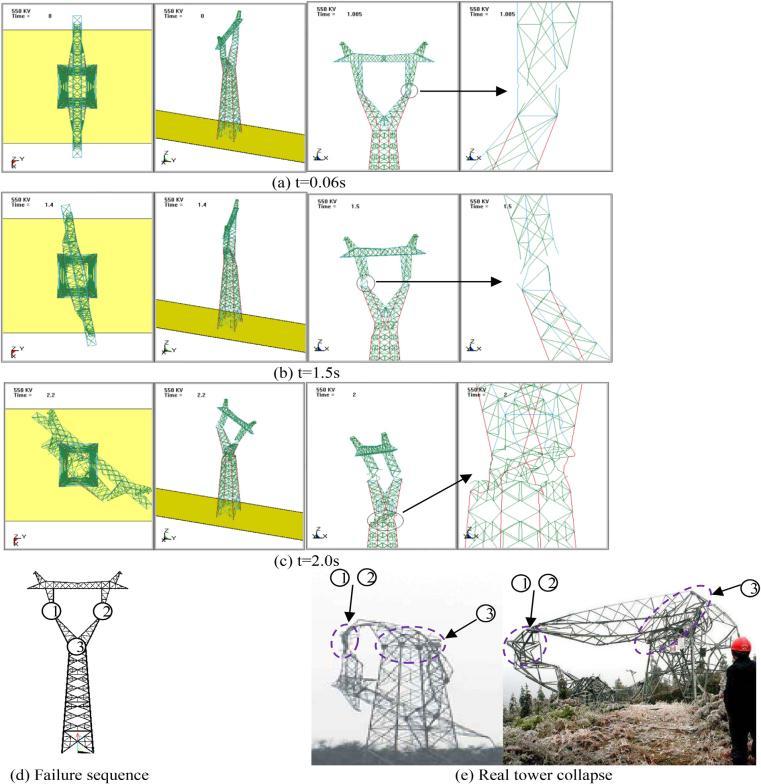
Fig. 2.4 shows the progressive collapse process of the tower. At 0.06 s, the unbalanced torsion due to line fracture leads to the fracture of a few structural members
International
e-ISSN: 2395-0056
Volume: 09 Issue: 08 | Aug 2022 www.irjet.net p-ISSN: 2395-0072
which connect the middle V-part and upper part of the tower, as shown in Fig. 2.4(a). Then, the middle V-part startstotwist. The structural memberswhichconnectthe middle V-part and upper part of the tower on the other side also fracture at 1.5 s. Thanks to the fixed supports of towerbottom,thebottompartofthetowerremainssteady undertorsionalforce.At2.0s,theconnectingcomponents between middle V-part and bottom part of the tower all fracturewhichleadstothe wholecollapseofthetower. As shown in Fig. 2.4(d), the upper part of the tower breaks into pieces from the middle V-part firstly, followed by the breakage between the middle V-part and bottom part of thetower.AsshowninFig.17(e),thecollapseofthetower inthesimulationshowsasimilarpatternwiththecollapse of the real wine-cup shape tower. The bottom part of the tower normally would not collapse, only if the failure happensatthetowerfeetconnections.
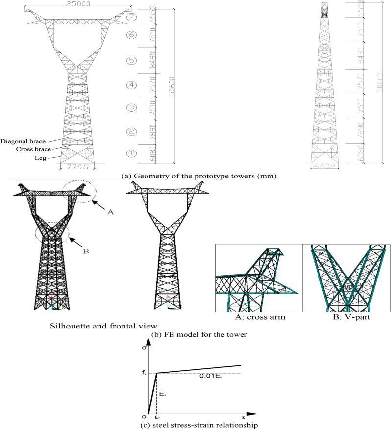
The finite element (FE) model of the prototype tower is developedbyusingANSYSasshowninFig.5(a).BEAM188 3D beam element withuser-defined profile is used to simulate leg members and cross-bracemembers. This element works best with the default choice in solutioncontrol. 3D uniaxial tension-compression truss element LINK8 withoutbending capacity is used to simulate diagonal-brace members. Materialnonlinearity and large deflection capabilities are available for bothBEAM188 and LINK8 elements. Both ends of the braces are assumed tobe pinned. The stress-strain relationship of steel is shown in Fig. 5(b).According to the investigation of power transmission tower collapseaccidents, the failure normally would not occur at thelegfeetconnection,exceptthattheboltsusedtofixleg feetaresabotaged.Therefore,thebottomendofthemodel is fixed. Geometric nonlinearityis considered in the finite elementmodel.
Fig.2.4 Progressive collapse simulation.
Fig.2.5 Prototype towers and the finite element model.
Theexistingtower,modelUA,hasapartiallytaperedform, with thecolumn member sections changing at three different heights (Fig. 6).Symmetries are maintained on both the axes in the plan view, making it simple for the designer in estimating and assigning the possible loads acting on the tower structure. Angle sections are used in
International Research Journal of Engineering and Technology (IRJET) e-ISSN: 2395-0056
Volume: 09 Issue: 08 | Aug 2022 www.irjet.net p-ISSN: 2395-0072
theentiremodel.Theprofileisconsiderablysimple,where the first bay is 3 m in height, followed by 8 bays of 2 m height each. This is owing to the bracings that are equally spaced. There are a total of 428 members altogether comprising of columns and bracings at varying levels. The column sections change at three different heights, while thebracingmembersectionsremainthesameintheentire model.
Fig 2.6 Sections groups considered in Model UA.
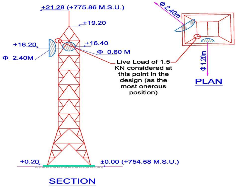
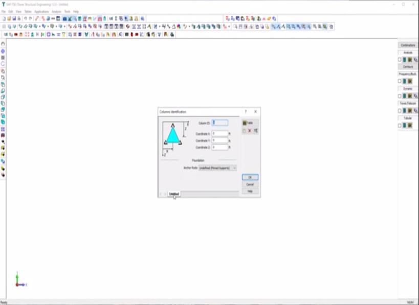
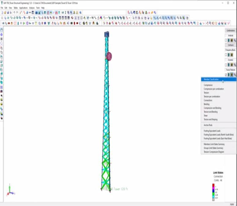
Therealtowerispositionedatanelevatedbaseof20mm above the existing ground level. As shown in Fig. 7 there are two antennas of different sizes, having radius 1.2 m and0.6m,facingdifferentdirectionsonthetower.Looking at the plan and section, the positions of the antennas can be known. Their positioning is fixed and cannot be changed as they are directed towards the satellite that transmits signals to these receivers. Orientation is critical, hence the antennas shall be fixed at the exact height and direction as per the recommendations from the service provider. The live load is considered as 1.5 kN. By engineeringjudgement,thisisthemostonerouscondition, and hence will display the worst condition for which the towerwillbedesigned.
Fig.2. Existing tower location - plan and section.
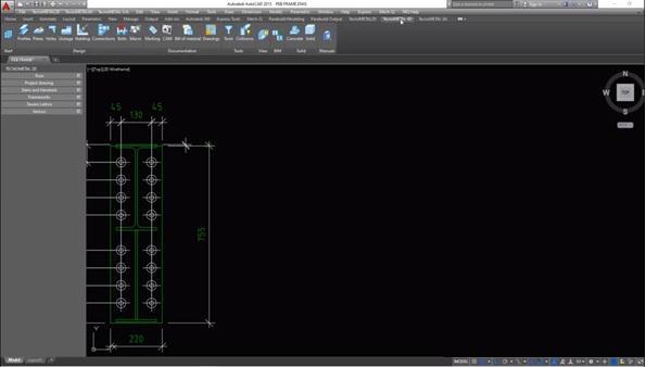
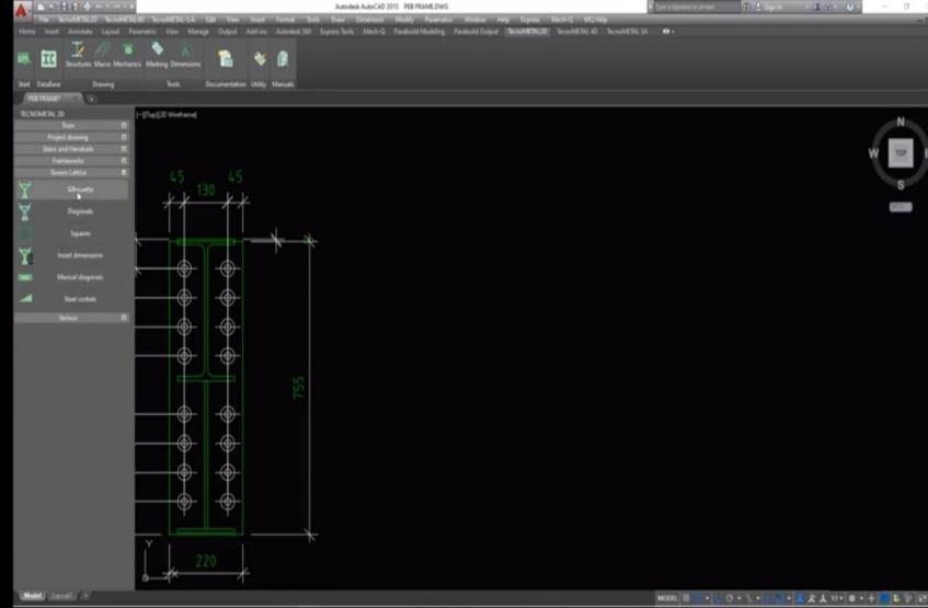
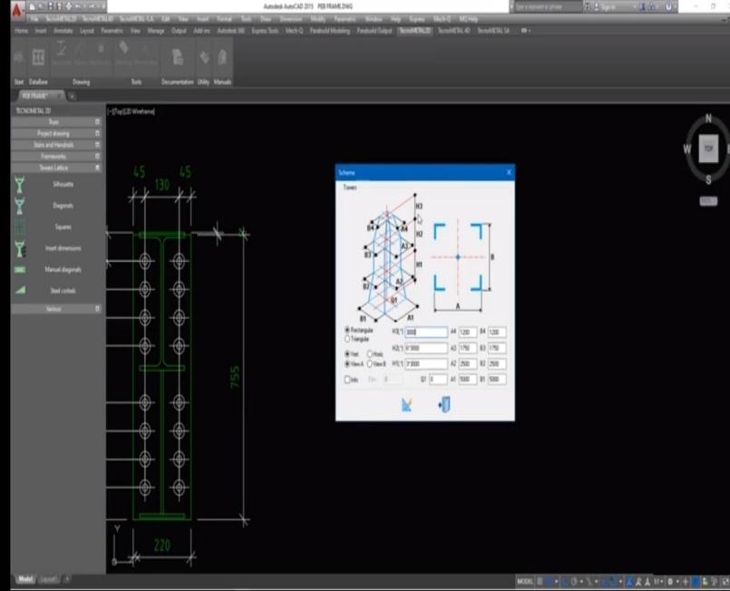
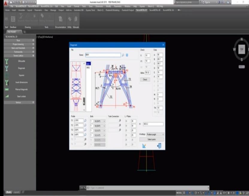
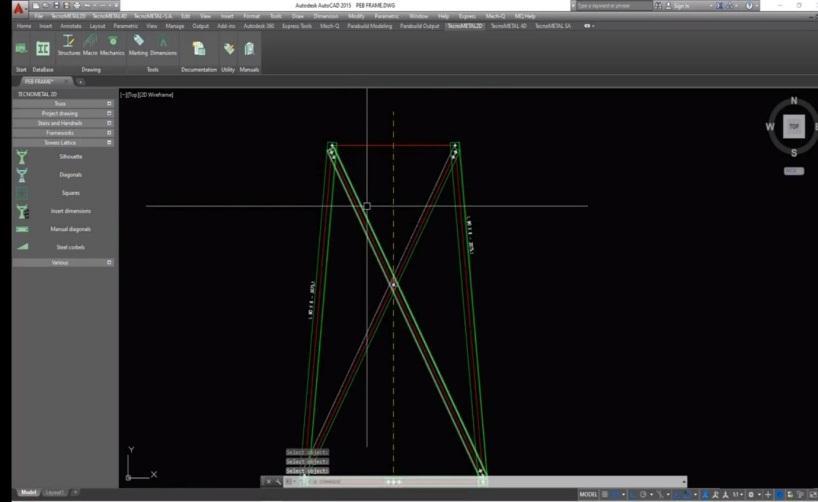
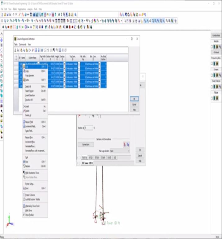
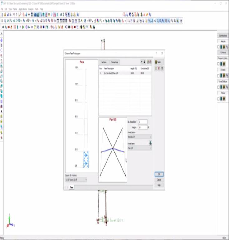
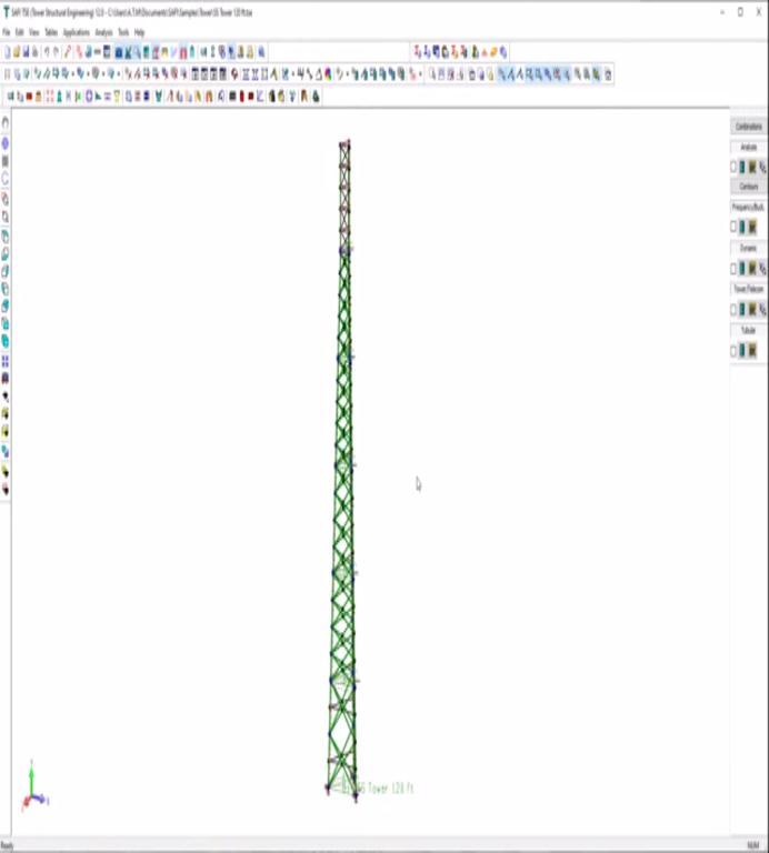
Modelling of telecommunication tower is perform in AutoCADsoftware.Inthissoftwarewiththeaidofspecific keywords like definition of point, line connections further section development were used to specify the developmentofamobiletower.
International Research Journal of Engineering and Technology (IRJET) e-ISSN: 2395-0056
Volume: 09 Issue: 08 | Aug 2022 www.irjet.net p-ISSN: 2395-0072
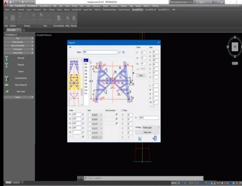
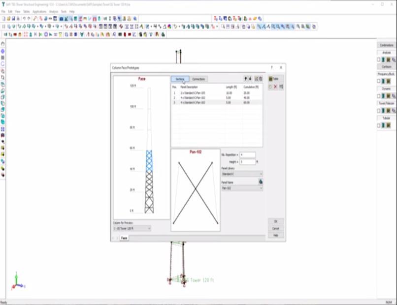
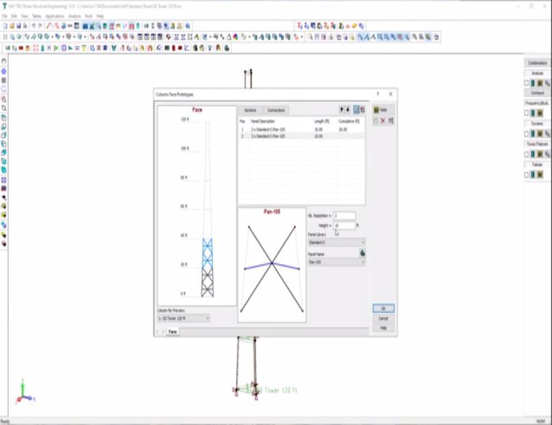
In Fig 4.4 the mobile tower is developed using different complex cross-sectional section cross bars/ties inorder to maintain the connection between critical load carrying members and further they were connected in such a way the load transferred properly and each cross-member remains under safe condition with respect to maximum loads
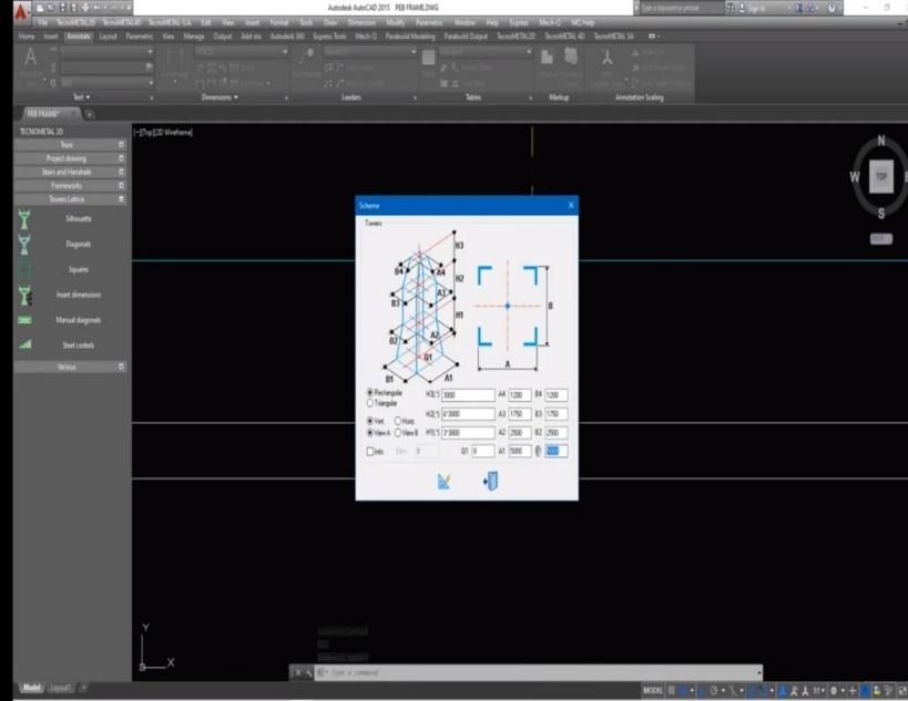
Using the finite element method, the tower bar was modeled as a 3D truss and 3D beam element to maintain the dynamic properties of the structural model. The main parametersthataffectthenaturalfrequencyofthebranch tower,andthevibrationmodesassociatedwiththem.The main purpose of the modeling strategy adopted was to study the structural behavior of the branch towers and prevent the development of disturbing structural mechanisms that could lead to uneconomical or unsafe structures. The towers (50m, 70m, 90m) examined in this study have a truss-like shape with a square cross section. Thehot-rolledanglesections,connectedbybolts,formthe mainstructureaswellasthebracesystem.
International Research Journal of Engineering and Technology (IRJET) e-ISSN: 2395-0056
Volume: 09 Issue: 08 | Aug 2022 www.irjet.net p-ISSN: 2395-0072
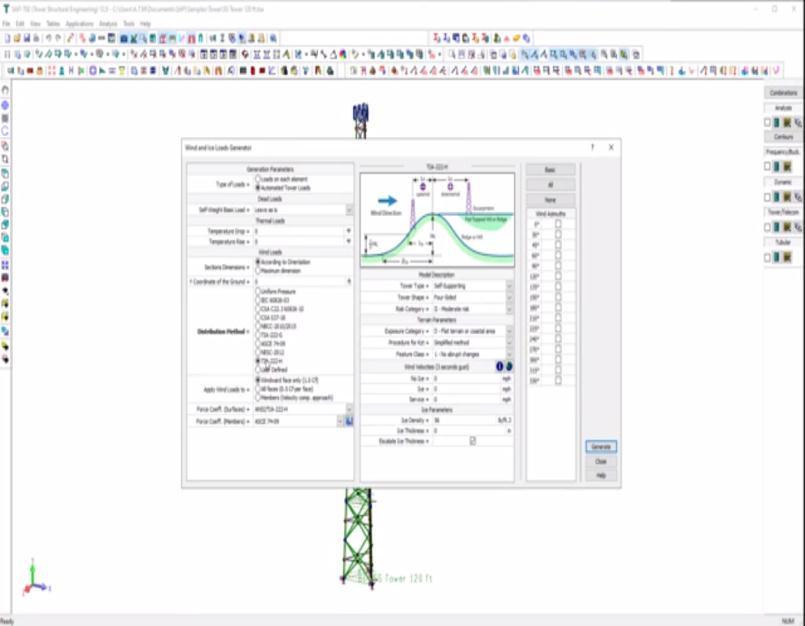
Prestressed cables support key structures that must be under constant tension. Some of these cables are connected to specific rod sets that are placed to improve the torsional stiffness of the system. This study took into accountthevertical loadsacting(the weightofstructures, stairs,antennas,cables,etc.).Themainhorizontalloadwas theeffectofthewindonthetower.Thesehorizontalloads were calculated according to the method described in BraziliancodeNBR6123(NBR6123,1988)andappliedto the nodes of the branch tower. Two wind load cases related to actions perpendicular and diagonal to the towers face were considered in this analysis. Theadopted guy prestress loads were in accordance to the valuesdescribed in the Canadian Code CSA S37-94 (CSA S37-94,1994).
Towermodelinghascausedproblemsrelatedtothelossof continuityin partsofthestructureduetothepresenceof hinges connected to 3D finite truss elements. The apex angle (main landing gear) is usually connected by three bolts, so the design assumptions are strict. Truss connections are considered flexible, so truss elements are used to model the angle at which a moment break occurs. On the other hand, using only one screw for diagonal or horizontal diagonal connection creates another discontinuity. In-plane movement can be considered flexible, but out-of-plane movement ignores the twist and bend continuity that exists in the structure. To overcome this problem, dummy bars, without mass and with low axial stiffness, were incorporated to the structure. In this process every new bar represents the suppression of an internaldegreeoffreedom.Althoughthetowershaveonly four bars in the horizontal plane defined by a typical transversal section it is still necessary to add a fifth dummy bar to create two isostatic triangles. If this restraint was not considered a simple structural mechanismcollapsewouldoccur.Anotherreasonforusing thesebarsistoimprovethestructuretorsionstiffness. All the abovementioned aspects allied to all the difficulties associated with the investigated tower geometry and to the truss finite element characteristics highlight the fact that the traditional truss design is not the bestrecommended methodology to be used. It should be stressedthatthelargenumberofdummybars,adoptedto enablethestructuralanalysistobeperformed,isthemajor disadvantageofthisstructuralmodellingstrategy
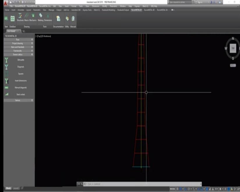
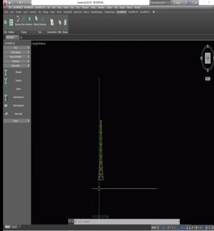
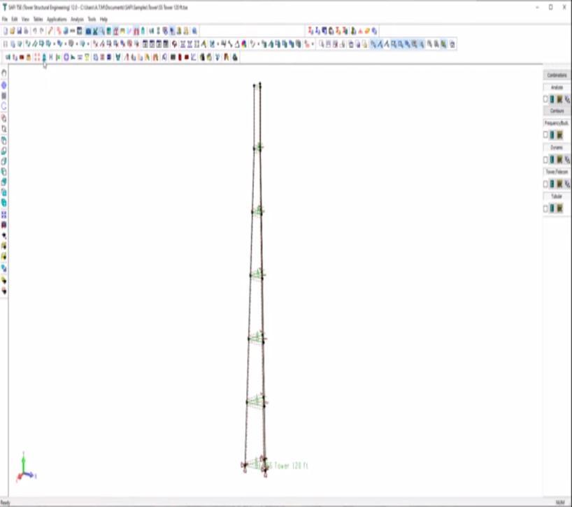
In fig 4.1 the mobile tower of different height 50 m, 60 m and70mrespectivelywasdefinedtopbedevelopedaFEM model. The developed FEM model was prepared using Triangular and Quad shaped elements of specific shapes and sizes. The core elements were the transformed into differentlayerstoobtaindifferentsizeoftowers.
International Research Journal of Engineering and Technology (IRJET) e-ISSN: 2395-0056
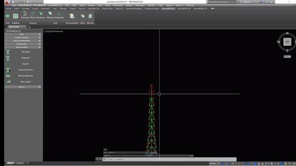
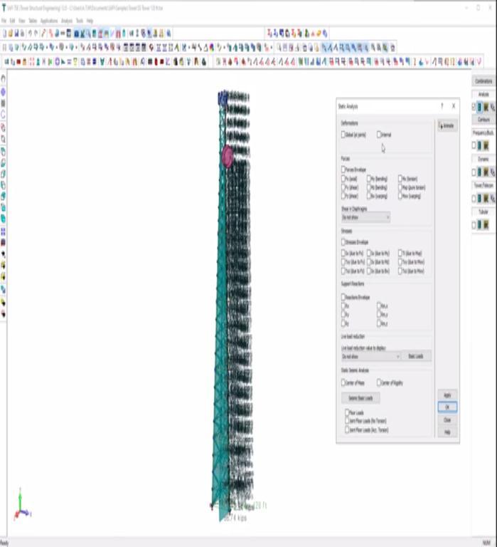
applicationof loads.In this case,the mobile tower isfixed at the bottom of the base with all degree of freedom as zero (means constant). After that the wind loads (taken from the reference paper) is applied on the structure to obtaintheperformanceofthestructurewithrespecttothe loads.
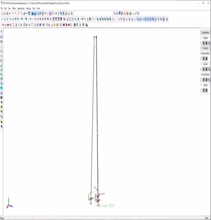
In order to solve a FEM problem the most critical thing to betakenintoaccountisthatthewholestructurehastobe properly constrained. The structure developed has to define fully with respect to its boundary condition and
Fig. 4.3 Applied border conditions and material assignments
Volume: 09 Issue: 08 | Aug 2022 www.irjet.net p-ISSN: 2395-0072 © 2022, IRJET | Impact Factor value: 7.529 | ISO 9001:2008 Certified Journal | Page710
International Research Journal of Engineering and Technology (IRJET) e-ISSN: 2395-0056
Volume: 09 Issue: 08 | Aug 2022 www.irjet.net p-ISSN: 2395-0072
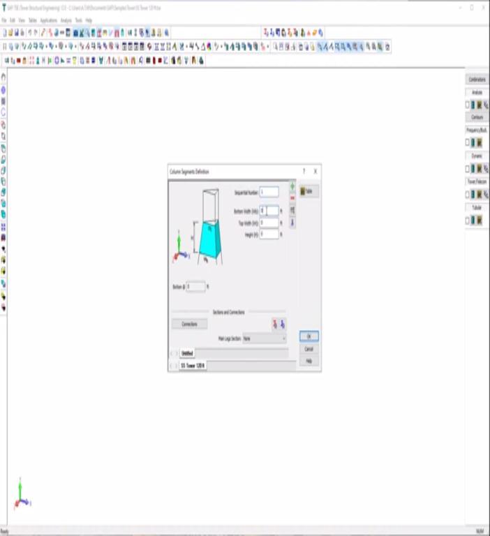
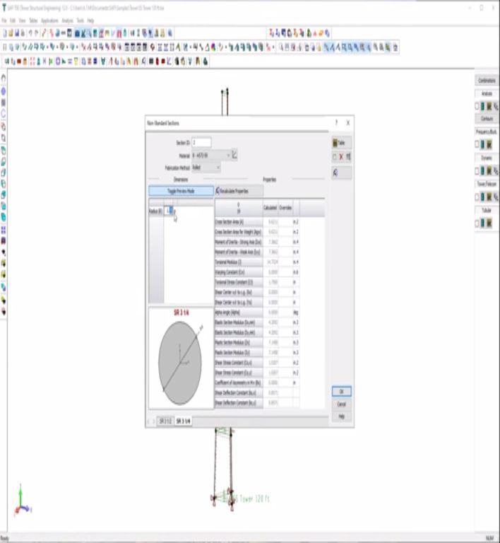
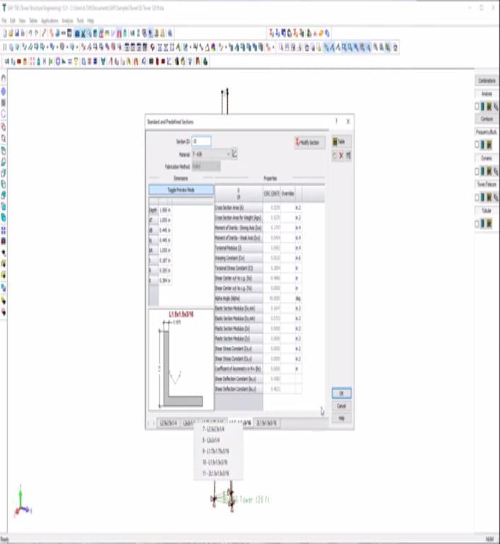
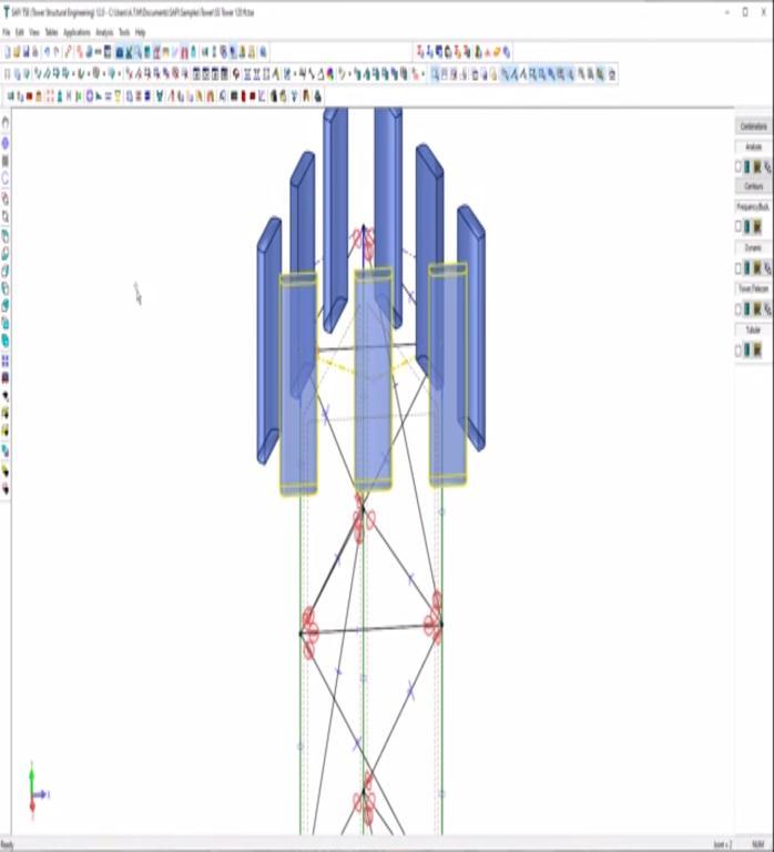
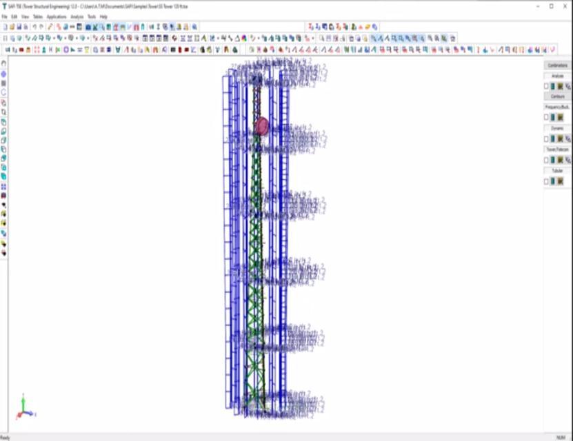
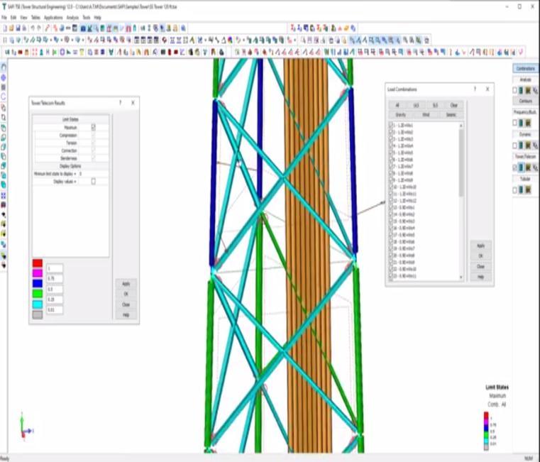
In Fig. 4.4, it is indicated that the mobile tower is developed with aid of different elements and all the elementsdevelopedwillrequiredefiningthecross-section oftheelementstoobtainthedisplacementandthestresses in the structure. Therefore, in this case the sections of different elements are defined with respect to different conditions of the load action upon it and also the position theelementisplaced.
International Research Journal of Engineering and Technology (IRJET) e-ISSN: 2395-0056
Volume: 09 Issue: 08 | Aug 2022 www.irjet.net p-ISSN: 2395-0072
Fig.4.5 Different Cross tie members
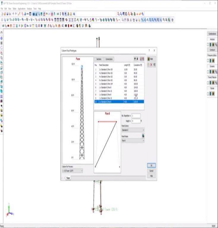
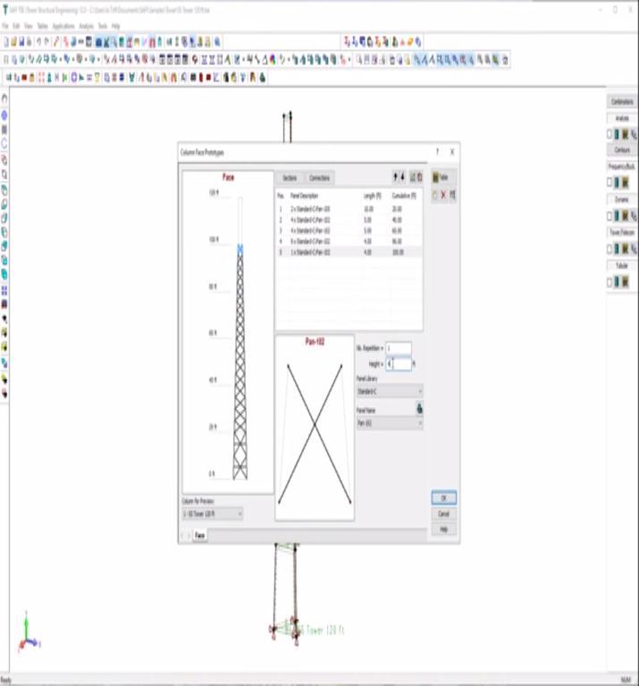
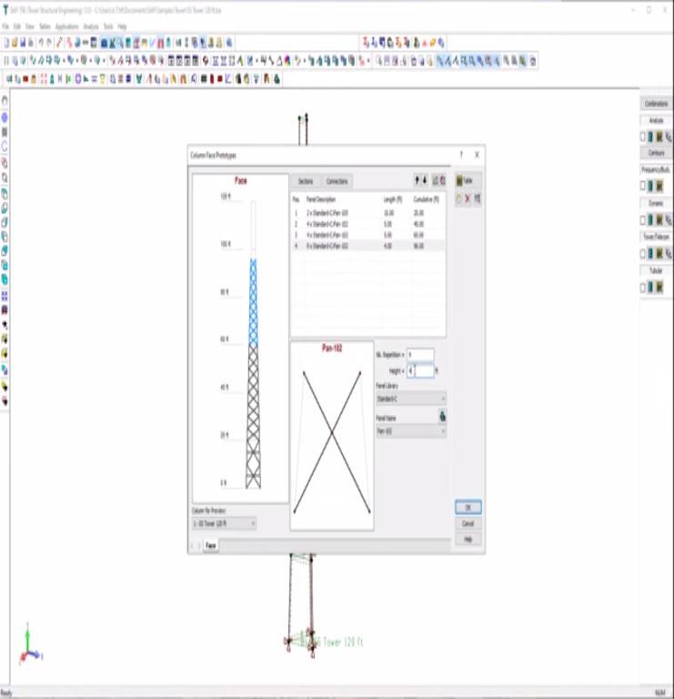
Fig.4.6 Mobile tower with complete cross tie members
© 2022, IRJET | Impact Factor value: 7.529 | ISO 9001:2008 Certified Journal | Page712
International Research Journal of Engineering and Technology (IRJET) e-ISSN: 2395-0056
Volume: 09 Issue: 08 | Aug 2022 www.irjet.net p-ISSN: 2395-0072
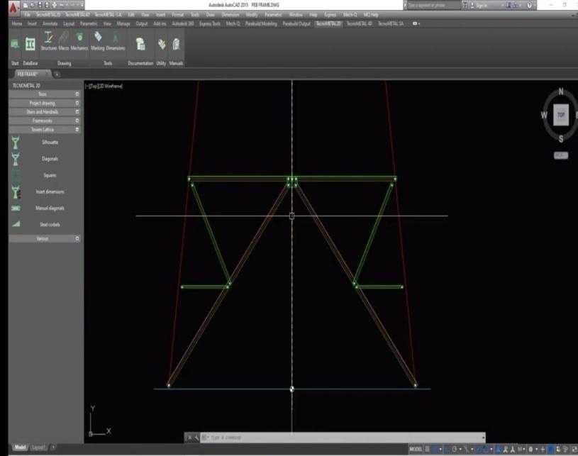
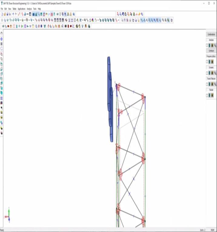
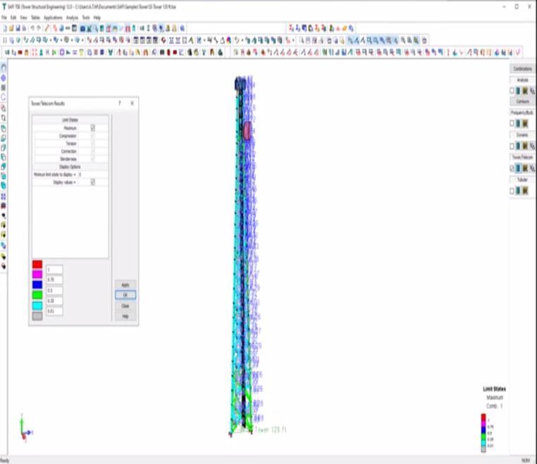
Differentmobiletowersweredesignedwithrespect tothe height of the tower but irrespective of that the model of the structure developed remains more of less the same. Crossmembertiesarespecificallyusedwiththedefinition of proper glued contacts so the contact definition within the surfaces remains the structures to act as a single structureandappropriateloadtransfer.
Fig. 4.7 Complete mobile tower with attachments
International Research Journal of Engineering and Technology (IRJET) e-ISSN: 2395-0056
Volume: 09 Issue: 08 | Aug 2022 www.irjet.net p-ISSN: 2395-0072
International Research Journal of Engineering and Technology (IRJET) e-ISSN: 2395-0056
Volume: 09 Issue: 08 | Aug 2022 www.irjet.net p-ISSN: 2395-0072 © 2022, IRJET | Impact Factor value: 7.529 | ISO 9001:2008 Certified Journal | Page715
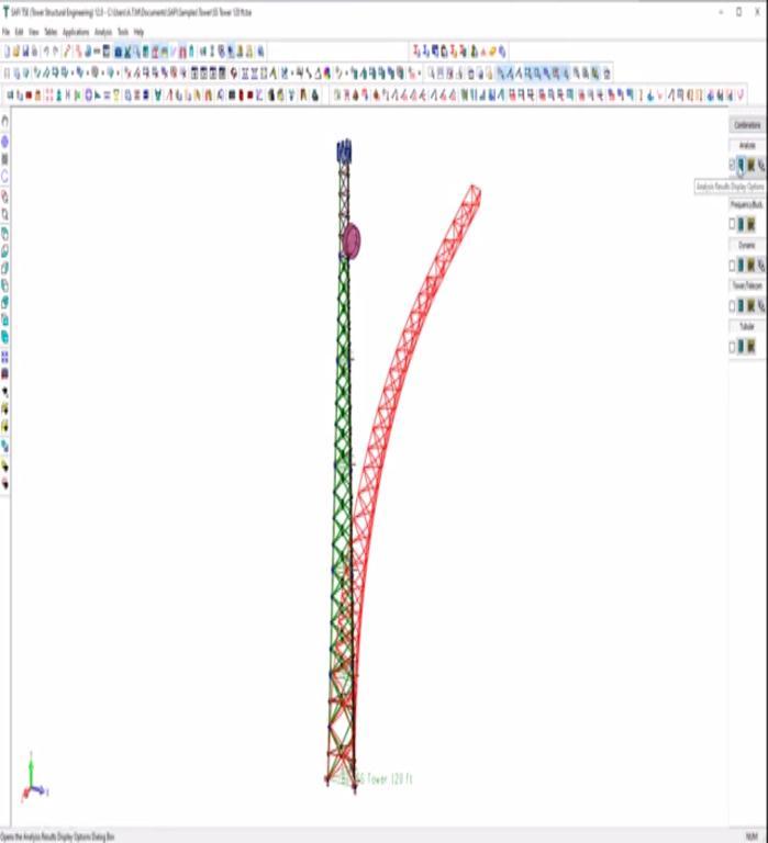
Fig 4.9 Vibration analysis of towers with height 50 m, 60 m and 70 m respectively
International Research Journal of Engineering and Technology (IRJET) e-ISSN: 2395-0056
Volume: 09 Issue: 08 | Aug 2022 www.irjet.net p-ISSN: 2395-0072
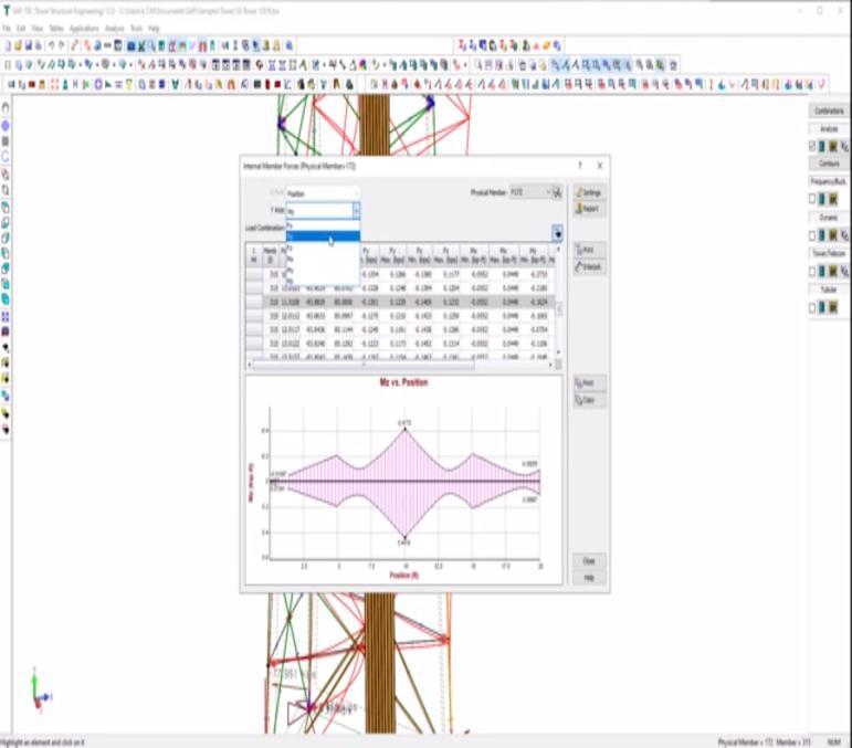
Fig. 4.10 Different modes of vibration on 50 m mobile tower
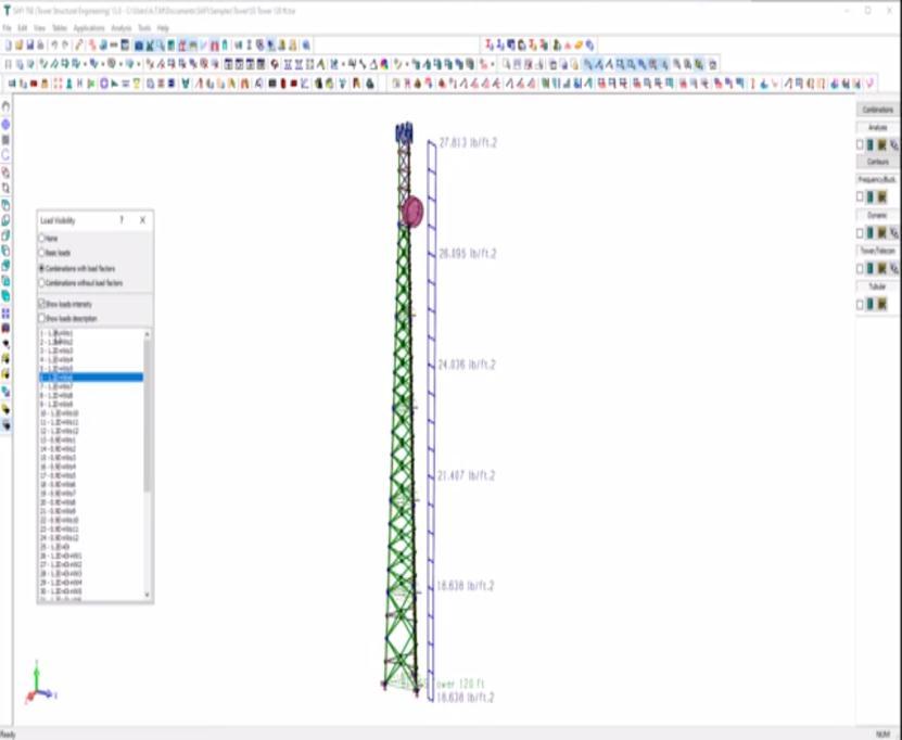
The impact loads considered in this analysis are selfweightandtwowindloadcases.Inthesecases,horizontal wind loads are applied perpendicularly and diagonally to the face of the piers. The transverse wind load was calculated according to the procedure described in the Brazilian code NBR 6123 (NBR 6123, 1988) and was appliedtothesteelnodesofthetower.Theresultsofstatic
International Research Journal of Engineering and Technology (IRJET) e-ISSN: 2395-0056
analysis of cell towers for towers with bars are studied (heights 50 m, 70 m and 90 m), according to the three structuralmodelsmentionedabove.Themaximumvalues of stress and transverse displacement are presented and compared.
The start line for each production process/product optimization was Taguchi’s optimization philosophy. However,thisphilosophyisbeingglobalcriticizedbecause of its incapability to resolve multi goal optimization problem. To remove this, it was observed in the literature that utility of Grey relational analysis, desirability feature approach,softwaretheory,TOPSIS,fuzzyinferencesystem (FIS), and most important issue analysis (PCA) [33-35], in my opinion incorporated with Taguchi method. The most important motto is to transform more than one targets into an equal unmarried goal feature; that may sooner or later be optimized via way of means of Taguchi method. However,thosetechniquesdependonafewassumptions.
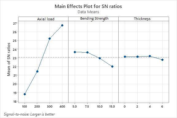
There isa loss featurewhichdescribesthedeviationfrom the target(preferred level)andinaddition convertedinto S/Nratio.TheconvertedS/Nratioislikewisedescribedas first-rate assessment index. The least variant and the choicest layout are acquired through reading S/N ratio. The better the S/N ratio, the greater solid the attainable first-rate. It additionally reduces the sensitivity of the machineoverallperformancetosupplyofvariant.
There are three S/N ratios of common interest for optimizationofstaticproblems:
In this approach, the closer to the target value, the better andthedeviationisquadratic
The lower is better approach held when a company desires smaller values.The formula for these characteristicsis;
It is required when a manufacturer desires higher values of a characteristic. The formula for these characteristicsis; ∑
Here, is the average of observed values; is the variance of observation and is the number of observations
However, Taguchi method is considered only for single-objective optimization problems. It cannot be utilizedfor getting the single optimal setting of process parameters considering more than one performance parameter.
Volume: 09 Issue: 08 | Aug 2022 www.irjet.net p-ISSN: 2395-0072 © 2022, IRJET | Impact Factor value: 7.529 | ISO 9001:2008 Certified Journal | Page717
Taguchi’s experimental approach has been followed to minimize the experiment trails, and L16 orthogonal array has been used to perform the experimentalruns.Besides,ANOVAhasbeenperformedto find out the significance of process variables. Axial Load, Bending Strength and Thickness are taken as input parameters and maximum displacement as a Output parameters
International Research Journal of Engineering and Technology (IRJET) e-ISSN: 2395-0056
8 200 15 4 10 9 300 5 4 21 10 300 7.5 6 19.5 11 300 10 0 17.6 12 300 15 2 15.4 13 400 5 6 20 14 400 7.5 4 24.3 15 400 10 2 22.6 16 400 15 0 20.3
Table 2 Response Table for Signal to Noise Ratios
Larger is better
Level Axial Load Bending Strength Thickness
1 18.82 23.66 23.14 2 21.44 23.63 23.13 3 25.23 22.95 23.19 4 26.74 21.99 22.77 Delta 7.92 1.67 0.41 Rank 1 2 3
Table 3 Response Table for Means
Level Axial Load Bending Strength Thickness
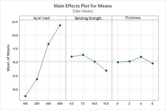
1 8.750 16.000 14.975 2 11.875 16.325 15.125 3 18.375 15.050 15.950 4 21.800 13.425 14.750 Delta 13.050 2.900 1.200 Rank 1 2 3
Regression Equation
Volume: 09 Issue: 08 | Aug 2022 www.irjet.net p-ISSN: 2395-0072 © 2022, IRJET | Impact Factor value: 7.529 | ISO 9001:2008 Certified Journal | Page718
Maximum Displacement = 6.45 +0.04565AxialLoad0.287BendingStrength+0.007Thickness
International Research Journal of Engineering and Technology (IRJET) e-ISSN: 2395-0056
Volume: 09 Issue: 08 | Aug 2022 www.irjet.net p-ISSN: 2395-0072
Table 4 -Maximum Displacement Numerical vs Regression equation S.No MaximumDisplacement Numerical Regression Equation 1 9.5 9.58 2 9 8.87 3 8.5 8.17 4 7.1 6.75 5 14.5 14.15 6 14.24 13.42 7 12.92 12.75 8 11.30 11.05 9 19.03 18.73 10 18.92 18.03 11 17.6 17.27 12 15.4 15.85 13 23.92 23.31 14 23.05 22.58 15 22.6 21.85 16 20.3 20.40
Coefficients
Term Coef SE Coef T-Value P-Value VIF
Constant 6.45 1.45 4.45 0.001
AxialLoad 0.04565 0.00344 13.29 0.000 1.00 Bending Strength -0.287 0.104 -2.76 0.017 1.00
Thickness 0.007 0.172 0.04 0.966 1.00
S R-sq R-sq(adj) R-sq(pred) 1.53652 93.88% 92.35% 87.60%
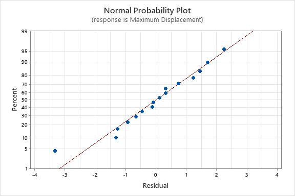
Source DF Adj SS Adj MS F-Value P-Value Regression 3 434.789 144.930 61.39 0.000
AxialLoad 1 416.784 416.784 176.54 0.000 Bending Strength 1 18.000 18.000 7.62 0.017
Thickness 1 0.004 0.004 0.00 0.966
Error 12 28.331 2.361 Total 15 463.120
International Research Journal of Engineering and Technology (IRJET)
e-ISSN: 2395-0056
Volume: 09 Issue: 08 | Aug 2022 www.irjet.net p-ISSN: 2395-0072
1. A.N. Nayak and Dr.S.K. Bhattacharya. Behavior of joints with rectangular and square hollow sections. Journal of the Institution of Engineers, CivilEngineeringDivision.78:116-122,Nov1997.
The developed method in this study is less conservative than traditional methods. The proposed methodology, as it uses 3D bean truss model for modelling the whole mobile structure relevanttowindandseismicloads.
2. BerdingDanielandCharneyFinleyA.Theeffectof modeling parameters on the wind drift of steel frame buildings. 2007 Structures Congress: New HorizonsandBetterPractices,ASCE.
The mobile tower with different heights of same configuration namely 50 m, 60 m and 70 m were developed using FEM technique to obtain the natural displacement and stresses developed usingdifferentloadsets.
3. Da Silva J.G.S. et al. Structural assessment of current steel design models for guyed steel telecommunication towers for radio antenna. JournalofConstructionalSteelResearch.61:11081134,2005.
Foraheightof 50mtowerrestingonthebuilding Xbracingiseconomicalintheformofdeflectionat thetopofthetower
4. Gomathinayagam S.et al. Dynamic Response of Lattice Tower with Antenna under Wind Loading.Journal of the Institution of Engineers (India).87:37-43,2000.
If the height increases then X bracing proves uneconomicalandKbracingproveseconomical.
5. Gucuyen Engin et al. Effect of changes on joint connections of steel lattice towers due to environmental loads. International Journal of EngineeringandIndustries.2(11),2011.
Magnitude of displacement in tower of smaller size is lower with same thickness on action of sameintensityblastloads.
Magnitude of stresses in tower of smaller size is lower with same thickness on action of same intensityblastloads
6. Harikrishna P. et al. Analytical and Experimental Studies on the Gust Response of a 52m Tall Steel Lattice Tower under Wind Loading. Computers and Structures, 70:149-160, 1999. Structural EngineeringResearchCentre,Chennai.
Intensity of displacement in tower design combination showed an increase with the enhancement in the intensity of blast loads. The maximum displacement of 50 mm happens at 2495 N load while at 195 N load the maximum displacementwas12mm.
7. Jiang W.Q. et al.Accurate modelingof joint effects in lattice transmission towers. Engineering Structures.33:1817–1827,2011.
8. Sullins Eric James. Analysis of radio communication towers subjected to wind, ice and seismic loadings.MS notion, (2006)Facultyofthe Graduate School of the University of Missouri,Columbia.
ANOVA analysis is also carried to analyse the parametricperformanceofMobiletowerdesign.
Taguchi analysis is performed for analysis of the parametersofMobiletowerdesign
9. Cello F.Carril Jr., Nicholas Isyumov, Reyolando M.L.R.F Brazil (2003) "Experimental Study of The Wind Forces on Rectangular Lattice CommunicationTowerswithAntennas"Journalof Wind Engineering and Industrial Aerodynamics, vol.91pp.1007-1022.
International Research Journal of Engineering and Technology (IRJET) e-ISSN: 2395-0056
Volume: 09 Issue: 08 | Aug 2022 www.irjet.net p-ISSN: 2395-0072
10. Ananias Kudzys (2006). "Safely of Power Transmission Line Strictures’ under Wind and lee Storms"EngineeringStructure,vol.28pp.682-689
11. NitinBhosale, Prabhat Kumar, PandeyA.D.[1], (2012):“Influenceofhoststructurecharacteristics on response of rooftop telecommunication towers”,InternationaljournalCivilandStructural Engineering, Volume2,Issue No3, 2012, ISSN NO. 0976-4399.
12. Ananias Kudzys (2006). "Safely of Power Transmission Line Strictures’ under Wind and lee Storms" Engineering Structure, vol.28pp.682-689
13. NitinBhosale, Prabhat Kumar, PandeyA.D.[1], (2012):“Influenceofhoststructurecharacteristics on response of rooftop telecommunication towers”,InternationaljournalCivilandStructural Engineering, Volume2,Issue No3, 2012, ISSN NO. 0976-4399.
14. Grekavicius L, Hughes JA, Tsavdaridis KD, Efthymiou E. Novel morphologies of aluminium cross-sections through structural topology optimisation techniques. In: The 13th International Aluminium Conference (INALCO 2016). 21–23 September 2016, Naples, Italy; 2016b.
15. Groen JP, Sigmund O. Homogenization-based topology optimization for high-resolution manufacturable microstructures. Int J Numer MethEng2018;113(8):1148–63.
16. Hajirasouliha I, Pilakoutas K, Moghaddam H. Topology optimization for the seismic design of truss-like structures. Comput Struct 2011;89(7–8):702–11.
17. Holmes JD, Banks RW, Roberts G. Drag and aerodynamic interference on Microwave dish antennasandtheirsupportingtowers.JWindEng IndAerodyn1993;50:263–70.
18. Jiang C, Jia H. Evolutionary based intelligent algorithm for topology optimizationof structure. Sixth international conference on intelligent systems design and applications.California: IEEE; 2006.p.897–902.
19. KefalA,SohouliA,Oterkus E,YildizM,SulemanA. Topology optimization ofcracked structures using peridynamics. Continuum Mech Thermodyn2019;31(6):1645–72.
20. Kentli A. Topology optimization applications on engineering structures. IntechOpenpublications; 2019.
21. Nielsen MG, Støttrup-Andersen U. Advantages of using tubular profiles for telecommunication structures 31 August/2 September Quebec City. London: Taylor & Francis Group plc; 2006. p. 45–51.
22. Nicolaou A, Tsavdaridis KD, Efthymiou E. Topology optimisation study for the design of lattice towers. In; The 9th Greek National Steel StructuresConference.5–7October,2017,Larissa, Greece; 2018.<http://eeme.ntua.gr/proceedings/9th/ Papers/063_PAP_Nicolaou.pdf.
23. NoiiN,AghayanI,HajirasoulihaI,KuntMM.Anew hybrid method for size and topology optimization of truss structures using modified ALGA and QPGA.JCivEngManage2016.ISSN1392-3730.
24. ISO12494.2001.AtmosphericIcingofStructures. InternationalstandardISO12494:2001(AnnexD).