International Research Journal of Engineering and Technology (IRJET) e-ISSN: 2395-0056

Volume: 09 Issue: 08 | Aug 2022 www.irjet.net p-ISSN: 2395-0072
International Research Journal of Engineering and Technology (IRJET) e-ISSN: 2395-0056
Volume: 09 Issue: 08 | Aug 2022 www.irjet.net p-ISSN: 2395-0072
1
2
3
1Subhash Gopi, Division Manager, Cyient Ltd, Manikonda, Hyderabad, India.
2Maharshi Reguri, Senior Design Engineer, Cyient Ltd, Manikonda, Hyderabad, India.
3HarshaVardhan Yeruva, Senior Design Engineer, Cyient Ltd, Manikonda, Hyderabad, India.
4Omprakash Adalam, Division Manager, Cyient Ltd, Manikonda, Hyderabad, India.
***
4
Abstract - Turbine and compressor disks with Airfoil blades are the critical components of Gas turbine engines as they play a vital role in engine performance. Structural strength and integrity at different rotating speeds and temperatures in operating conditions are essential for the better service life of these disks. The first step in the Design and Development of a Rotor Disk is an iterative concept design phase using CAD (Computer-Aided Design) software followed by a validation process with FEA (Finite Elemental Analysis) software to meet its structural integrity requirements. The paper aims to demonstrate the process improvement using a less iterative automation approach over the mentioned conventional approach in developing the final CAD geometry concept that is structurally and thermally viable.
The automation tool interpolates the intermediate radial points (also referred to as radial stations) from the given input design parameters required for precise mapping of the elastic stresses developed in the disk. It calculates elastic tangential and radial stresses in the disk using the inbuilt mathematical equations at each radial station. All the governing equations for elastic stresses are taken from the classic “Manson method” [1] to calculate elastic stresses in the rotating disk. Design iterations are carried out using the tool by changing the input design parameters to validate the stresses at each radial station and finalize the design concept. The validated input geometrical parameters are exported to CAD to build a final optimized design concept. Final stress variation contour plots and critical results are generated in the tool dashboard. It saves almost 80% of design and developmental efforts as compared to the conventional approach.
Key Words: Rotor Disk, Gas turbine engine, Elastic stresses, Automation, Design Concept, CAD, FEA
Inproductdevelopment,CADgeometryfortheGasturbineRotorDiskpartisderivedthroughaniterativeconceptdesign process.Itneedsadetailedstructuralandthermalevaluationtofreezethedesignconceptthatcanwithstandalltheinduced stressesinthecomponentduringfieldoperation.Thepaperaimsatbringingoutanalternativeefficientoptiontoreducethe leadtimeintheconceptdevelopmentoftheGasturbinedisk.
FirstlythegeometricalanddesignparametersofthecompressororturbinediskarepopulatedintheAutomationtoolthat generatesseveralinterpolatedpoints.Thetangentialandradialstressesarecalculatedusingthe"Mansonequations"[1]at eachinterpolatedradial pointalsocalledtheRadial stations. The resultantstressat eachRadial station isvalidated with allowablestresscriteriafortheStructuralandThermalintegrityofdisksfromtheinbuiltequations.Oncealltheinterpolated pointsarevalidated,thefinalizedgeometricalparametersrelatedtothevalidatedinterpolatedpointsarefurthertakenas inputstogeneratetheCADmodelfromtheAutomationtool.Iteliminatestheiterativeprocessofmodelingandanalyzingusing CADandFEAsoftware,thusreducingoverallturnaroundtime,costandmakingitmoreproductive.
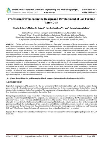
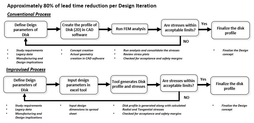
Figure1showstheconventionalandcurrentimprovisedprocessapproachofRotorDiskconceptdesigntogeneratetheCAD Geometry.
International Research Journal of Engineering and Technology (IRJET) e-ISSN: 2395-0056
Volume: 09 Issue: 08 | Aug 2022 www.irjet.net p-ISSN: 2395-0072
Figure 1: ConventionalandCurrentimprovisedprocessapproachofDiskConceptDesign
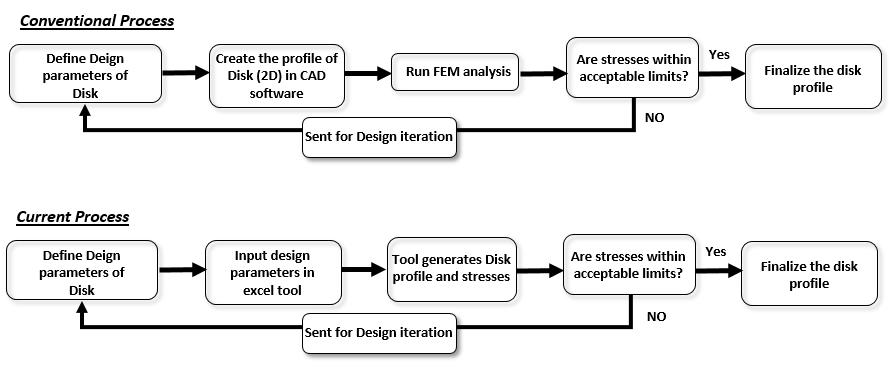
TurbineandcompressordisksofaGasturbineneedtobestructurallyviableastheirfailureinservicecouldresultinsevere enginedamage.Sodeterminationandvalidationofstressesinthediskunderoperatingconditionsplayanimportantroleinthe designofdisks.Theconceptbuildingstageindiskdesignrequiresnumerousiterationsandmayconsumealotoftimein extractingtheresultsforeachiteration.TheAutomationtooldevelopedcancalculatethestressesinthediskatvariousradial locationsfromboretorim.Solet’sunderstandtheDiskconfigurations,Designparameters,andtheGoverningequationsused fromtheMansonmethod[1]ofelasticstressescalculationfor Disks.Inthelatersection,wewilllookintotheresultsand validationtobuildanoptimizedDiskconcept.
DiskdesignconfigurationsasshowninFigure2areofthreemajortypes[2],whicharealsoconsideredindesigningthetool: 1. Webdisk 2. Hyperbolicdisk 3. Ringdisks
Figure 2:Diskconfigurationsusedforthetool
2022, IRJET | Impact Factor value: 7.529 | ISO 9001:2008 Certified Journal |
International Research Journal of Engineering and Technology (IRJET) e-ISSN: 2395-0056
Volume: 09 Issue: 08 | Aug 2022 www.irjet.net p-ISSN: 2395-0072
ThedevelopedautomationtoolhasaninbuiltbaselinediskgeometryselectionoptionasperFigure2.AlltheGeometricdesign parametersandDimensionsarereflectedasinputfieldsinthetoolbasedonthedisktypeselectionasshowninFigure3.Users canpickthedisktypeandgivethenecessarydesignerinputsaspertheDesignrequirement.
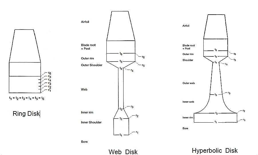
Figure3showsalltheprimaryinputswiththefeasibilityofpickingthenecessaryunits.Theparametersarerelatedtothedisk criticaldimensions,bladeparameters,materialproperties,rotationalspeed,andtemperatures.AlltheDiskdesignparameters fedhereinturnfeedthegoverningequationsasinputsinFigure4whichcalculatestheRadial(σr)andTangentialstresses(σt) ateachradialstationlocation(n).Thestationlocation(n)isderivedfrominterpolateddatausingtrigonometricfunctionsand thebaselinegeometricparameters.Thetoolalsohastheoptiontogivetemperatureinputsateachstationlocationshownin Figure3whichhelpsinbuildingnotonlystructuralbutevenathermallyviableDiskdesignconcept.
ThetoolusestheMansonmethod[1]governingequationswhicharefinite-differenceformulationstocalculatetheTangential andRadial stressesina rotatingdisk.Ina thinrotatingdisk ofvariablethickness,thestateofstressatanyradiuscanbe completelydefinedbythetwoprincipalstresses,theRadial(σr)andTangential(σt)stresses.Belowarethetwofundamental governingequationsusedtoderivethetwounknownstressesfromtheMansonapproach[1]
Note:SeetheDetailsoftheSymbolsusedaboveinFigure4
Thefirstoftheseaboveequationscanbeobtainedfromtheconditionsofequilibriumofanelementofthedisk;thesecondis fromthecompatibilityconditions,whicharemathematicalstatementsoftheinterrelationbetweentheradialandtangential strains in a symmetrical disk. The equilibrium and compatibility equations result in differential form defining relations between the stresses at disk radius r and those at a radius infinitesimally removed from r. To facilitate a solution, the differentialequationsarerewritteninthefinite-differenceequationsshowninFigure4toarriveattheelasticstressesateach radiallocationr(alsoreferredtoasradialstationsinthetool).
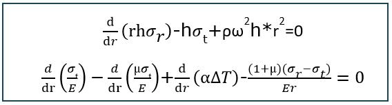
Toderivetheseradiallocationsandusethegoverningfinite-differenceequationsinthetool,thebaselinegeometric2Dprofile ofthediskisdividedintoseveralincrementalinterpolatedradialpoints.These“n”numberofpointsatincrementalradial heightsareusedasinputstothegoverningManson’sfinite-differenceequationstocalculatethestressesateachradiallocation.
2022, IRJET | Impact Factor value: 7.529 | ISO 9001:2008 Certified Journal | Page691
International Research Journal of Engineering and Technology (IRJET) e-ISSN: 2395-0056
Volume: 09 Issue: 08 | Aug 2022 www.irjet.net p-ISSN: 2395-0072
Nowallgoverningfinite-differenceequationsareusedintheAutomationtoolto
elasticRadialandTangentialstresses asshowninFigure4atallthe“n”radialstations.Thesestresseswithinterpolatedpointsaremappedasresultsbythetool whichwouldbeexplainedinthenextresultsection.
2*(rn-rn-1)(ρnhnrn 2+ρn-1hn-1rn-1 2) C'n ((µn)/En)+((1+µn)(rn-rn-1))/2Enrn D'n (1/En)+((1+µn)(rn-rn-1))/2Enrn F'n ((µn-1)/(En-1))+((1+µn-1)(rn-rn-1))/(2En-1rn-1)
G'n (1/(En-1))-((1+µn-1)(rn-rn-1))/(2En-1rn-1) H'n (αn∆Tn)-(αn-1∆Tn-1)
Kn ((F'nDn-FnD'n)/(C'nDn-CnD'n) Ln (-(G'nDn+GnD'n)/(C'nDn-CnD'n))
K'n ((F'nCn-FnC'n)/(C'nDn-CnD'n)
L'n (-(C'nGn+CnG'n)/(C'nDn-CnD'n))
Mn (H'nDn+HnD'n)/(C'nDn-CnD'n)
M'n (C'nHn+CnH'n)/(C'nDn-CnD'n)
Ar,n (Kn*Ar,n-1)+(Ln*At,n-1);whereAr,a=0,At,a=1
At,n (K'n*Ar,n-1)+(L'n*At,n-1)
Br,n (Kn*Br,n-1)+(Ln*Bt,n-1)+Mn;whereBr,a=Bt,a=0
t,n (K'n*Br,n-1)+(L'
Thederivedinterpolatedpointsateach
location(n)playacriticalroleinbuildingtheoptimizedfinaldesignconcept. Thetoolcalculatesstressesateach
themagainstbaselineallowablestresslimits.Multipleiterations canbecarriedoutwithaclickbychangingthebasicgeometricalparametersearliershowninFigure3,whichinturngenerates anewsetofinterpolatedcoordinateswithstressresults.Thisflexibilitytochangethedesignparameterstogettheresultsina quickturnaroundmakestheprocesseffective.TheoutputDiskcoordinatesarecapturedandthestressmagnitudeismapped
International Research Journal of Engineering and Technology (IRJET) e-ISSN: 2395-0056
Volume: 09 Issue: 08 | Aug 2022 www.irjet.net p-ISSN: 2395-0072
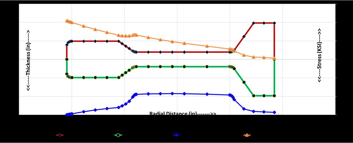
acrosstheradialstationsasshowninFigure5.Themagnitudeofthestressplotsischeckedfortheallowablestressmargin beforefinalizingthedesign.Oncethedesignermeetsthetargetedgeometricalandstressmarginshecouldfreezetheconcept andexportthegeometricparameterstoCADSoftwareforbuildingthefinalCADmodel.
CriticalstressresultsareextractedfromthestresscontourinFigure5.Alongwiththeprofile,theweightofthediskisalso generatedbythetoolwhichisalsoanecessaryattributetofreezetheconcept.Theconsolidatedreportenablesthedesignerto makeafinaldecisiononfreezingtheconceptbeforeexportingittoCADtobuildanoptimizedconceptmodel.
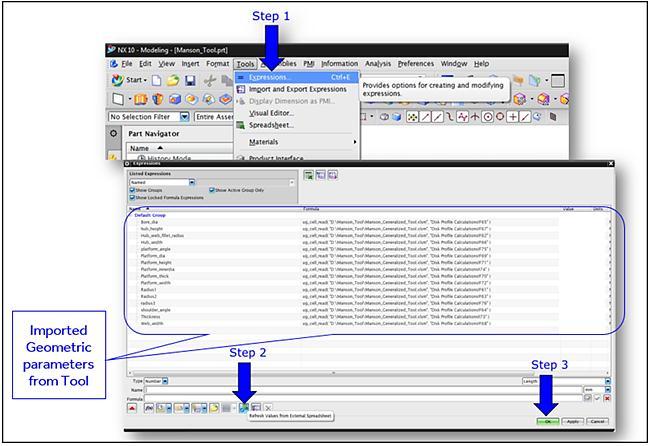
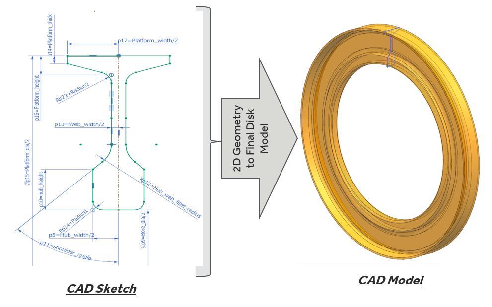
Once we are good with the geometry and the stress margins next step is to derive the CAD geometry using the finalized geometricparameters.NXCADsketchfollowedbyfinaldesign3Dconceptgeneratedbyimportingfinalizeddesignparameters fromthetoolasexpressionasshowninFigure6andFigure7.Asyounoticethatitisjustafewclicksandonetimejobafterthe toolvalidationiscompleted.
Figure 6:ImportingoffinalizedToolGeometricParameters(Dimensions)toCAD(NX)Software
2022, IRJET | Impact Factor value: 7.529 | ISO 9001:2008 Certified Journal |
International Research Journal of Engineering and Technology (IRJET) e-ISSN: 2395-0056
ExpressionImport:openNXfile Tools Expressions Refreshvaluesfromtheexternalspreadsheet
Figure 7:DerivedCAD(NX)GeometryfromimportedtoolDesignGeometricDimensions
Asaresultofthenewprocess,wecouldnowimproveproductivitybyapproximately80%comparedtotheconventionaldesign process. Figure8showsthe detailedcomparison ofimprovisedprocessstepsover theconventional approach.Thegiven processisforoneiterationandinreal-timediskconceptdesign,numberofiterationshavetobeperformedtofinalizethe designparameterswhichaddsfurthercostsavingsandproductivity.
Figure 8:ProductivitysavingsofApprox.80%withimprovisedprocess
AutomationofdesignprocessflowbringsupgreatproductivityfortheDesignengineers.Thepaperhasattemptedtobringone such automation of the Gas turbine Disk Design that could generate approx. 80% of productivity savings for each design
Volume: 09 Issue: 08 | Aug 2022 www.irjet.net p-ISSN: 2395-0072 © 2022, IRJET | Impact Factor value: 7.529 | ISO 9001:2008 Certified Journal | Page694
International Research Journal of Engineering and Technology (IRJET) e-ISSN: 2395-0056
iteration.Asthedesignprocessisiterativeinnaturethetotalproductivitysavingsmultiplywitheachdesigniteration.The automationgivesgreatflexibilitytoDesignersforabettersolutioninquickturnaroundtimeandincreasesproductivity.
ByviewingtheoutputstressesacrosstheradialstationandcriticalstressesintheDashboard,thedesignercanmakequick decisionsaboutfinalizingthedesignconcept.CADmodelsarebuiltwithoutswitchingfromFEAtoCADsoftwareeachtime. Oncethedesignerissatisfiedwiththeoutputofthetool,hecanusethegeometricparameterstogeneratethefinalbaseline CADmodelinjustafewclicks.
Thetoolisvalidatedbycomparingtheresultswithactualstructuralanalysisresultsandbotharealmostmatchingwitha negligible 2% deviation which is within the allowable Margin Of safety (MOS) requirements for the Disk design. The automationtoolmakestheDiskdesignsimple,economic,productive,anddesigner-friendly.
[1]S.SManson,“Determinationofelasticstressesingasturbinedisks.” https://www.academia.edu/2540868/Determination_of_elastic_stresses_in_gas-turbine_disks
[2]M.T.Tong,I.Halliwell,andL.J.Ghosn,“Acomputercodeforgasturbineengineweightanddisklifeestimation” https://www.semanticscholar.org/paper/A-Computer-Code-for-Gas-Turbine-Engine-Weight-and-TongHalliwell/47687573303c141037cf950486005e14946fb730
Overall17+yearsofexperienceinthefieldofEngineeringDesignanddevelopmentofCommercial GasTurbine,Industrial gasturbines,AeroEngineTestRigs,Aerostructureassemblies&Reverse Engineeringprojects.
10.5 years of experience in detail design and engineering of commercial aero engines. Creating componentManufacturingdrawings,AssemblydrawingsandLayoutdrawings
Having 5.5 years of experience in the field of Engineering Design and development involving in Design,Modeling,AssemblyandDraftingofGasTurbineEngineComponents.


Overall17+yearsofexperienceinthefieldofEngineeringDesignanddevelopmentofCommercial GasTurbine,Industrialgasturbines,AeroEngineTestRigs,Aerostructureassemblies&Reverse Engineeringprojects.ExperienceinAutomationusingML,AI,NLP,Artificialneuralnetworkswith PYTHONprogramminglanguage

Volume: 09 Issue: 08 | Aug 2022 www.irjet.net p-ISSN: 2395-0072 © 2022, IRJET | Impact Factor value: 7.529 | ISO 9001:2008 Certified Journal | Page695