International Research Journal of Engineering and Technology (IRJET) e ISSN: 2395 0056

Volume: 09 Issue: 07 | July 2022 www.irjet.net p ISSN: 2395 0072
International Research Journal of Engineering and Technology (IRJET) e ISSN: 2395 0056
Volume: 09 Issue: 07 | July 2022 www.irjet.net p ISSN: 2395 0072
1Mtech, Structural engineering, Ilahia college of engineering and technology, Muvattupuzha, Kerala, India 2Assistant Professor, Ilahia college of engineering and technology, Muvattupuzha, Kerala, India ***
Abstract Seismic forces are the one of the destructive forces acting on the building. The seismic forces adversely affect the building. Many researches are going on to reduce the adverse effect of seismic forces on the building.one of the method adopted to mitigate the seismic forces are the installation of seismic dampers. This paper mainly focuses on the installation of multi tubular dampers on beam column joint to mitigate the seismic forces. Rigid connections are considered in this study. ANSYS software is used for the analysis of models. Parametric study is conducted on models to find the effective size of the damper. Studies are conducted on various shapes of dampers like ellipse, oval, x shape, circular to find effective shape. Also, studies are conducted on various materials of damper to find damper of better performance. Then the effective damper is installed in a five storied building frame and analyze the building frame to find base shear and storey displacement
Key Words: Dual pipe dampers, Seismic forces, Building frames, Kobe earthquake, cyclic loading
Anearthquakeis the shaking of the surface of the earth resulting from a sudden release of energy in theearth'slithospherethat createsseismic waves Theseismicity, orseismic activity, of an area is the frequency,type,andsizeofearthquakesexperiencedovera particulartimeperiod
Earthquakesareoneofthemostdestructivenaturalhazards that cause huge amount of loss of life and property. Therefore,thereductionoftheirreparabledamageofthis natural hazard at the lowest cost has always been the ultimate goal of researchers and practitioners in the earthquakeengineeringfield[3].
Oneofthemethodsadoptedtoreducetheeffectofseismic forcesonbuildingistheinstallationofdualpipedampers.By installingthesedualpipedampersinbuilding,itabsorbsthe seismic forces coming in to the building and maintain the building in an elastic state. Amir Masoumi Verki , Adolfo Preciado[3] proposed experimental and analytical investigationsofenhancedsemi rigidconnectionswithdual pipedampers.Inthisstudy,anexperimentalandanalytical studyofasemi rigidconnectionwithDPDsisevaluated.The studiedmodelsinthisresearchhaveabeamconnectionto twosteelcolumnswithDPDswithasemi rigidconnection.
Also,ABAQUS®softwareisusedtoperformfiniteelement analysis Inthenextstep,oneoftheavailablelaboratories has been used to perform experimental tests. Then, the resultsbetweenFEMandtestedresultsmodelshavebeen compared.
Hossein Akbari Lor, Mohsen Izadinia, Parham Memarzadeh[4]proposedexperimentalandnumericalstudy of I shape slit dampers in connections . In this study, the proposed damper is installed and tested under cyclic loading.Basedontheexperimentalresults,theconnection hashighseismicperformanceandrotationalcapacitymore than0.04radians Also,theslitdamperconnectionhasmore moment capacity than other common connections and indicates a good hysteretic behavior. Also, local buckling didn’toccurontheflangesandwebofthebeam.Thecolumn and beam remain in elastic state. Some numerical models weremadeinABAQUSsoftware.Analysisresultshadgood agreement with experimental results and showed high energydissipationandductilityintheproposedconnection.
Jie Zheng, Chunwei Zhang [6] proposed experimental Investigation on the Mechanical Properties of Curved MetallicPlateDampers.Inthisstudy,proposesacurvedsteel plate damper to improve the seismic performance of structures. The theoretical analysis of the curved plate damperwascarriedoutderivingformulasofkeyparameters ofthecurvedplatedamperincludingelasticlateralstiffness, yield strength, and yield displacement. Moreover, a cyclic loadingtestoffoursetsofspecimenswasconducted,andthe hysteretic performance, ductility, energy dissipation performance,andstrainofthespecimenswerestudied.The resultsshowedthattheinitialstiffnessofthedamperwas large,noobviousdamagewasobserved,andthehysteresis loopwasfull.
AliAshasi Sorkhabi n, HadiMalekghasemi, AmirrezaGhaemmaghami b, OyaMercan[7] proposed experimental investigations of tuned liquid damper structure interactions in resonance considering multiple parameters.Inthisstudy,tunedliquiddampers(TLDs)are costeffectiveandlowmaintenancevibrationabsorbersthat can be used to suppress structural vibrations. A TLD dissipatesenergythroughliquidboundarylayerfriction,free surface contamination, and wave breaking. In this paper, usingastate of the artexperimentaltestingmethod,namely real time hybrid simulation (RTHS), a comprehensive
International Research Journal of Engineering and Technology (IRJET) e ISSN: 2395 0056
Volume: 09 Issue: 07 | July 2022 www.irjet.net p ISSN: 2395 0072
parametric study is conducted to investigate the effectiveness of TLDs During RTHS the TLD response is obtainedexperimentallywhilethestructureismodeledina computer,thuscapturingtheTLD structureinteractionin real time.Bykeepingthestructureastheanalyticalmodel, RTHS offers a unique flexibility in which a wide range of influential parameters can be investigated without modifyingtheexperimentalsetup.
MohammadMahdiJavidana,SeunghoChunbandJinkooKim [5]proposedexperimentalstudyonsteelhystereticcolumn dampersforseismicretrofitofstructures.Inthisstudy,the seismicperformanceofasteelcolumndamperisevaluated using cyclic loading tests of two one story one bay reinforced concrete (RC) frames before and after retrofit. The theoretical formulation and design procedure of the damperareexplainedfirstandthenthedetailsofthetests aredescribed.Theseismicperformancesofthetestframes are evaluated in terms of hysteretic behavior, energy dissipation,crackpattern,failuremechanism,anddamper behavior.Theanalyticalmodelofthedamperisestablished and verified using the experimental data. The seismic performance of the structure is evaluated and compared beforeandafterretrofitindetailusingpushover,nonlinear time history,andfragilityanalyses.Theresultsshowthatthe presented damper can efficiently reduce inter story drifts and damage of the structure. The details of modeling techniquesandsimulationsgiveninthisstudycanprovide guidelinesandinsightintononlinearanalysisandretrofitof RCstructures.
Rongqian Yang 1 and Xuejun Zhou 2[8] proposed experimental Research and Theoretical Analysis of the Seismic Behavior of Prefabricated Semirigid Steel Frame with X Shaped Braces. In this study, three semirigid connections which are convenient for prefabrication have beenproposedinthispaper.Basedonthem,thequasistatic test was conducted on three prefabricated semirigid steel frames with X shaped braces in order to investigate their hysteresis behavior, bearing capacity, energy dissipation capacity,andfailuremechanism.Acomparativeanalysisof the semirigid connections was made to analyze their advantagesanddisadvantages.Anumericalsimulationwas carriedoutviausingABAQUStoverifythetestresults,and thecausesoftheerrorswereanalyzed. Theresultsshowed thattheprefabricatedsemirigidsteelframeswithX shaped braces had good seismic behavior, the braces cooperated well with the steel frame in resisting lateral load, and the braces failed before the steel frame, which meant the structurehadtwoseismicfortificationlines.
Wei Guo XingyeWang , Yujie Yua,Xueyuan Chen , Shu Li a, Wenbin Fanga, Chen Zenga,YangWang a, Dan Bud[9] proposed experimental study of a steel damper with X shapedweldedpipehalves.Inthisstudy,anewsteeldamper named X shaped pipe damper (XPD), is proposed and examined.Theproposeddamperismadethroughwelding two oppositely positioned pipe halves to forma X shaped
core,andconnectingtheX shapedcoretosideplateswith fillet welds or circumferential welds. The XPD damper provides the lateral resistance and energy dissipation behaviorsinitiallythroughflexuralbendingofpipeplates, andlatterthroughthetensilestretchingatcompositepipe halves. Theoretical derivations of initial stiffness and yielding properties were conducted, and the nonlinear working mechanisms and seismic performance were investigated through cyclic quasi static tests. Effect of welding methodsand pipeconfigurationson thestiffness, strength, ductility and energy absorption efficiency of the XPDswerestudied.
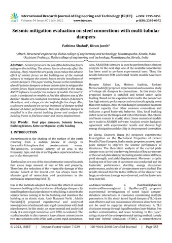
Dual pipe damper is fabricated of two horizontal pipes in contact welded to each other and to a top and bottom supporting plate at certain locations to optimize the performance.Sixlinesofweldareusedinthefabricationof DPD fourflarebevelgrooveweldsbetweenthepipesand supportingplatesandtwoflareVgrooveweldsbetweenthe pipes. The pipe material should be mild steel with a minimum of 25% elongation in tensile coupon test to guaranteeductilebehavior.Fig1showsamodelofdualpipe damper.
Fig1Modelofadualpipedamper.
The main objective of this paper is to identify the seismic performance of joint with a and without damper.Parametricinvestigationsforsizeoptimizationof thedamperinthebeamcolumnjointbyvaryingdiameter, width, thickness and number of the dampers and finding optimumperformance.Toinvestigatethecyclicperformance of the pipe connection under cyclic analysis to evolve it ultimate load, moment capacity, drift, ductility, energy absorptioncapacity
Thestudyisfocusedmainlyontherigidconnections
International Research Journal of Engineering and Technology (IRJET) e ISSN: 2395 0056
Volume: 09 Issue: 07 | July 2022 www.irjet.net p ISSN: 2395 0072
ThegeometricmodellingiscarriedoutinANSYSsoftware. BareframeismodelledinANSYSsoftware.Thebeam(B)and column(C)dimensions[8]aregiveninthetable1
Depth (mm) Flange width (mm)
Web thickness (mm)
Flange thickness (mm)
B 600 220 12 19 C 310 288 18.5 33
Table1Beamcolumndimensions
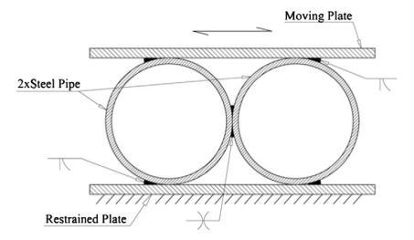
Geometric modelling of beam column joint without damperisdoneusingANSYSsoftware.Fig2showsamodel ofbeamcolumnjointwithoutdamper.
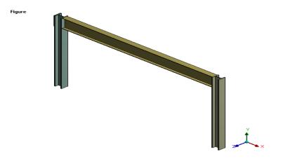
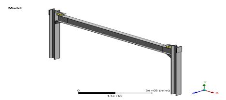
The geometric modelling is carried out in ANSYS software. Frame with damper is modelled in ANSYS software.Thebeam(B)andcolumn(C)dimensionsaresame asgiveninthetable1
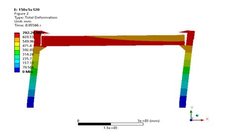
3.1.1 Modelling of beam column joint with damper Model1:150x5x120
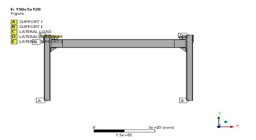
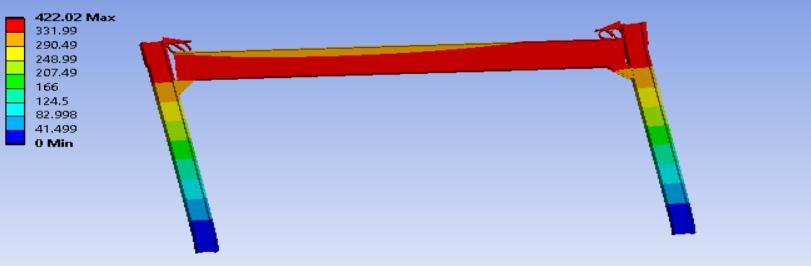
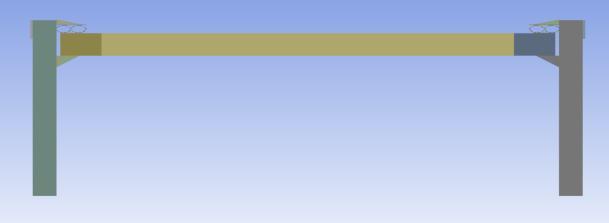
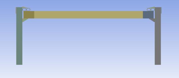
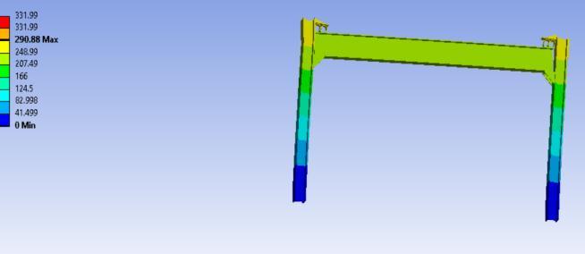
Fig4showsthemodelofframewith damper.Fig5shows theloadingdiagramandfig6showsthetotaldeformation diagram
Fig4 Modelofframewithdamper
Fig2 Modelofbeamcolumnjointwithoutdamper.
After modelling, meshing is done as rectangular mesh which is a 4 nodded mesh. Here a mesh size of 10 mm is adopted.Theloadisappliedtothebeamcolumnjoint.
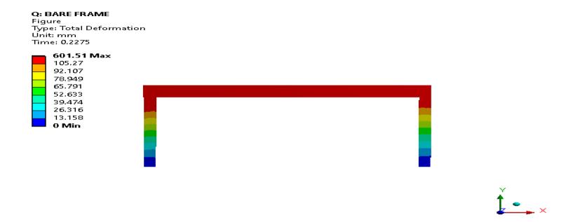
Nonlinear static analysis is carried out to find out the maximumloadcarryingcapacitybyusingANSYSsoftware. Fig3showsthetotaldeformationdiagramofbeamcolumn jointbytheapplicationofload.
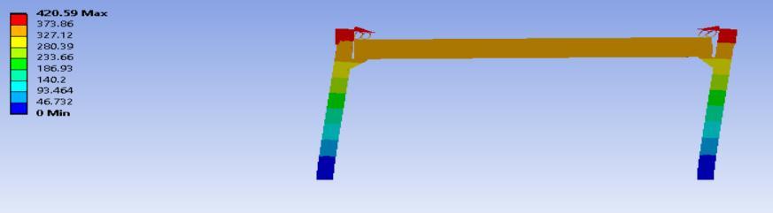
Fig5.loadingdiagram
Fig6Totaldeformationdiagram Model 2:150x10x120
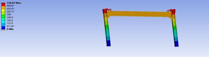
Fig7showsthemodelofframewithdamperandfig8shows thetotaldeformationdiagram.
Fig.3Totaldeformationdiagram
2022, IRJET | Impact Factor value: 7.529 | ISO 9001:2008 Certified Journal
International Research Journal of Engineering and Technology (IRJET) e ISSN: 2395 0056
Volume: 09 Issue: 07 | July 2022 www.irjet.net p ISSN: 2395 0072
Fig7 Modelofframewithdamper
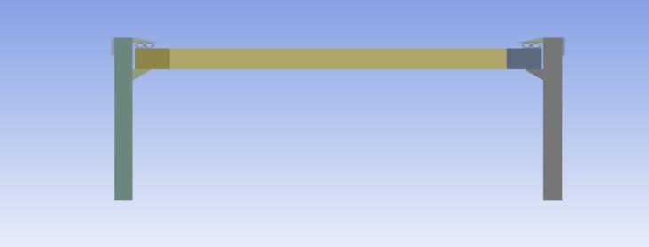
Fig11modelofframewithdamper
Fig8 Totaldeformationdiagram. Model 3:150x15x120
Fig 9 shows the model of frame with damper and fig 10 showsthetotaldeformationdiagram.
Fig9Modelofframewithdamper
Fig10Totaldeformationdiagram
Model 4:150x15x80
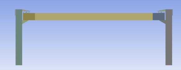
Fig 11 shows the model of frame with damper and fig 12 showsthetotaldeformationdiagram.
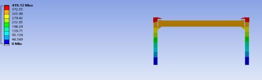
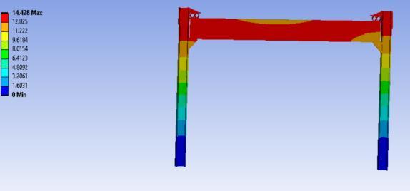
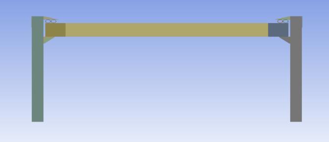
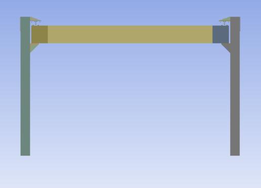
fig12 Totaldeformationdiagram
Model 5:200x5x120
Fig 13 shows the model of frame with damper and fig 14 showsthetotaldeformationdiagram.
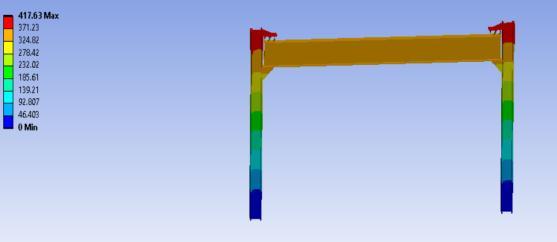
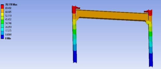
Fig13Modelofframewithdamper
Fig14Totaldeformationdiagram.
Model6:200x15x120
Fig15showsthemodelofframewithdamperandfig16 showsthetotaldeformationdiagram.
2022, IRJET | Impact Factor value: 7.529 | ISO 9001:2008 Certified
International Research Journal of Engineering and Technology (IRJET) e ISSN: 2395 0056
Volume: 09 Issue: 07 | July 2022 www.irjet.net p ISSN: 2395 0072
LOAD Vs DEFORMATION
Fig15Modelofframewithdamper
Load(kN)
Fig16 Totaldeformationdiagram. Model 7:200x15x80
Fig17showsthemodelofframewithdamperandfig18 showsthetotaldeformationdiagram.
Fig17Modelofframewithdamper
Fig18Totaldeformationdiagram.
3.1.2 Results and comparison
Fig19showsthegraphofcomparisonofvarious sizesofdampers
1000
800
600
400
200
0
1200 0 500 1000
Deformation(mm)
BARE FRAME 150x5x120 150x10x120 150x15x120 150x15x80 200x5x120 200x15x120 200x15x80
Fig19.parametricstudyondampers
Fromtheabovemodels,themodel200*15*120havemore ductilityandloadcapacity.So,theeffectivesizeofdamperis 200x15x120.
3.2 Damper with various shapes
Model 1: elliptical shaped damper
Frameismodelledwithsamedimensionsandelliptical damperisinstalledinbeamcolumnjoint.Fig20showsthe model of elliptical damper. Fig 21 shows the deformation diagramofellipticaldamper
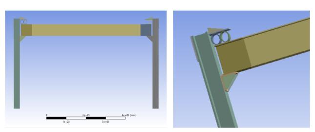
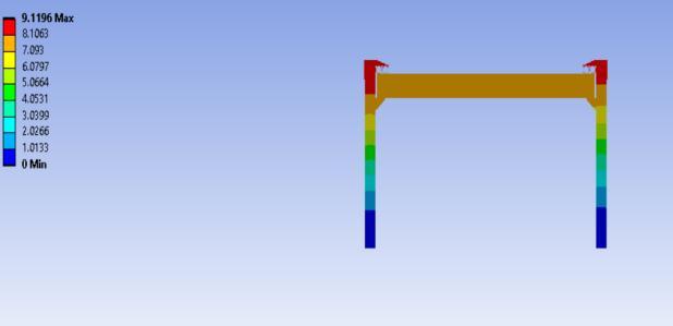
Fig20.Modelofellipticaldamper
Fig21.Deformationdiagramofellipticaldamper
2022, IRJET | Impact Factor value: 7.529 | ISO 9001:2008 Certified Journal
International Research Journal of Engineering and Technology (IRJET) e ISSN: 2395 0056
Volume: 09 Issue: 07 | July 2022 www.irjet.net p ISSN: 2395 0072
Frameismodelledwithsamedimensionsandovalshaped damperisinstalledinbeamcolumnjoint.Fig22showsthe model of oval damper. Fig 23 shows the deformation diagramofovaldamper.
Fig25.DeformationdiagramofXshapeddamper
Model 3: circular shaped damper
Frame is modelled with same dimensions and circular shaped damper is installed in beam column joint. Fig 26 showsthemodelofcircularshapeddamper.Fig27shows thedeformationdiagramofcircularshapeddamper.
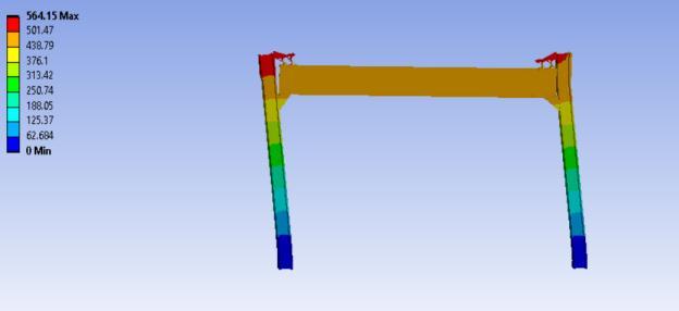
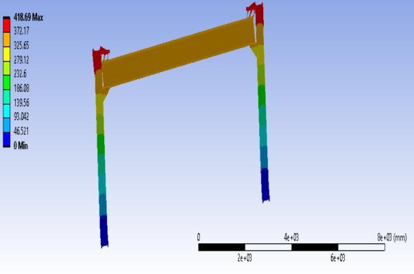
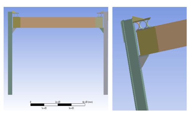
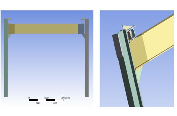
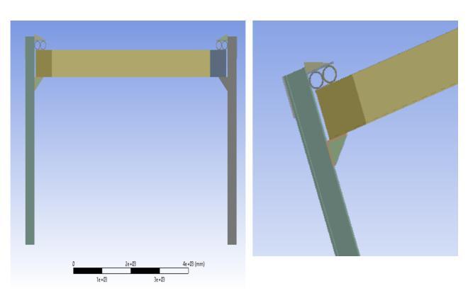
Fig22.Modelofovaldamper
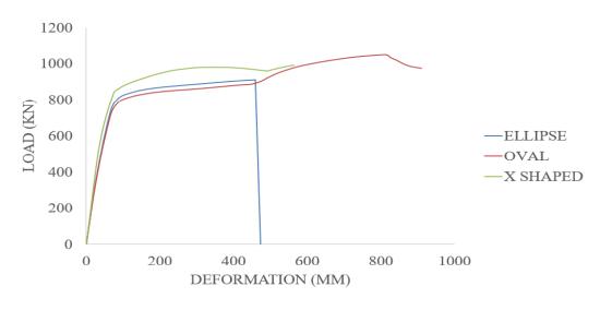
Fig23.Deformationdiagramofovaldamper.
Model 3: X shaped damper
Frame is modelled with same dimensions and X shaped damperisinstalledinbeamcolumnjoint.Fig24showsthe model of Xshapeddamper. Fig25showsthedeformation diagramofXshapeddamper.
Fig26.Modelofcircularshapeddamper
Fig24.ModelofXshapeddamper
Fig27.Deformationdiagramofcircularshapeddamper 3.2.1Results and comparison
Fig28showsthegraphofcomparisonofdifferentshapesof damper
Fig28.Graphofcomparisonofdifferentshapesofdamper
2022, IRJET | Impact Factor value: 7.529 | ISO 9001:2008 Certified Journal
International Research Journal of Engineering and Technology (IRJET) e ISSN: 2395 0056
Volume: 09 Issue: 07 | July 2022 www.irjet.net p ISSN: 2395 0072
Various shapes of models like ellipse, oval, x shape, circular is modelled in ANSYS software. From the above models, the circular shaped damper shows more load carryingcapacityandductility.
Frameismodelledwithsamedimensionsandovalshaped damperisinstalledinbeamcolumnjoint.Thematerialused hereisalowyieldingsteelwithyieldstrength100MPa.Fig 29showsthemodelofovalshapeddamper.Fig30showsthe deformationdiagramofovalshapeddamper.
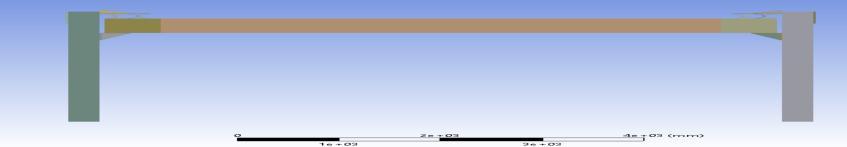
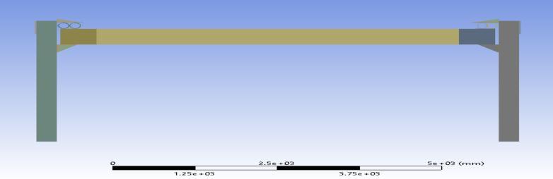
Fig32.Deformationdiagramofellipticalshapeddamper
Model 3: X shaped damper
Frame is modelled with same dimensions and X shaped damperisinstalledinbeamcolumnjoint.Thematerialused hereisalowyieldingsteelwithyieldstrength100MPa.Fig 33showsthemodelofXshapeddamper.Fig34showsthe deformationdiagramofXshapeddamper.
Fig29.Modelofovalshapeddamperdamper
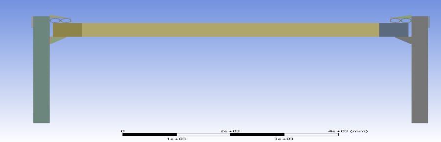
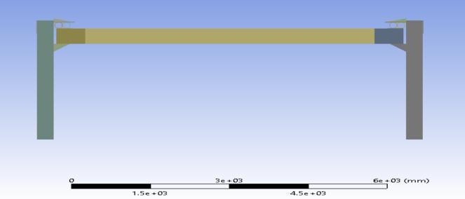
Fig30.Deformationdiagramofovalshaped
Frame is modelled with same dimensions and elliptical shaped damper is installed in beam column joint. The materialusedhereisalowyieldingsteelwithyieldstrength 100 MPa. Fig 31 shows the model of elliptical shaped damper.Fig32showsthedeformationdiagramofelliptical shapeddamper.
Fig33ModelofXshapeddamper
Fig31.Modelofellipticalshapeddamper.
Fig34.TotaldeformationofXshapeddamper
Frame is modelled with same dimensions and Circular shaped damper is installed in beam column joint. The materialusedhereisalowyieldingsteelwithyieldstrength 100MPa.Fig35showsthemodelofCircularshapeddamper. Fig 36 shows the deformation diagram of Circular shaped damper
Fig35.ModelofCircularshapeddamper
International Research Journal of Engineering and Technology (IRJET) e ISSN: 2395 0056
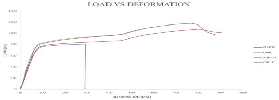
Fig36.DeformationdiagramofCircularshapeddamper
3.3.1Results and comparison
Fig37showsthecomparisonofdifferentmaterialsof dampers
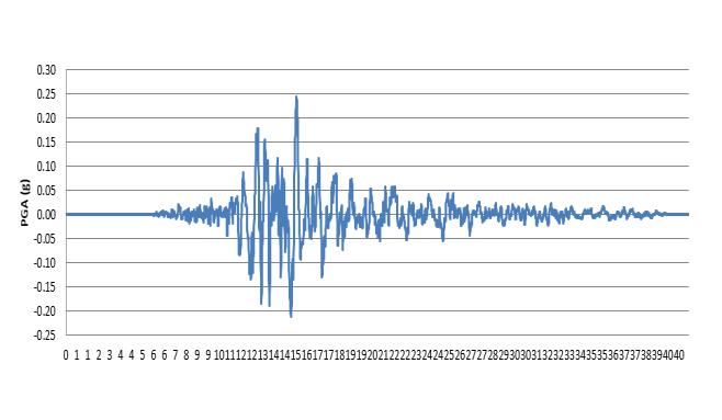
Fig39.AccelerationTimehistoryofKobeearthquake
Fig37.comparisonofdifferentmaterialsofdampers
Low yielding materials used in modelling of dampers. By modelling dampers with low yielding material, circular dampershowsmoreloadcarryingcapacity(1177.7kN)and ductility(12.629).
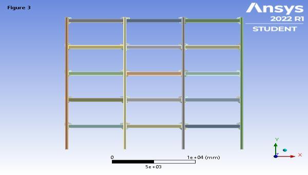
A five storied building frame is modelled in the ANSYS software without damper. Fig 38 shows the model of a buildingframewithoutdamper.
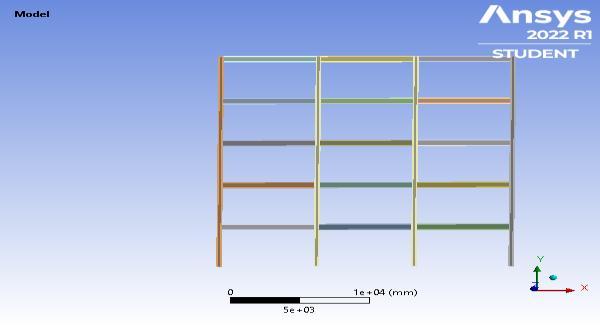
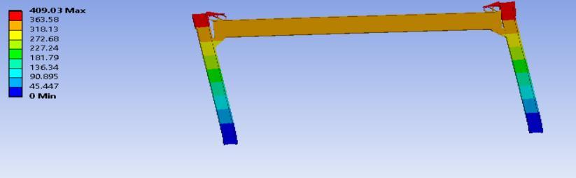
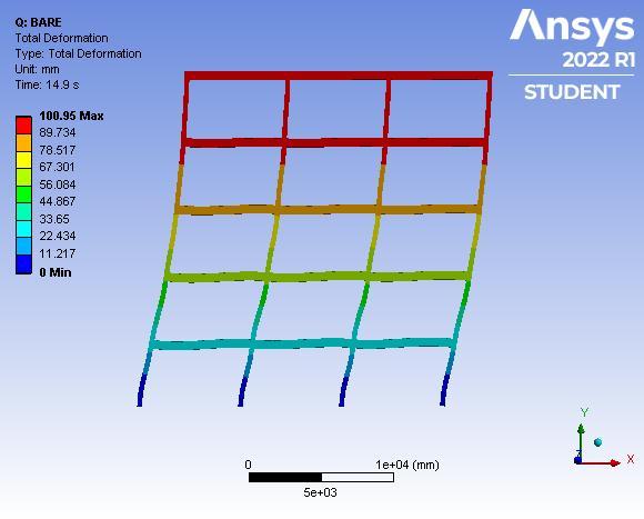
Fig4Deflectionofthebuildingframe.
4 2Analysis of Building frame with damper
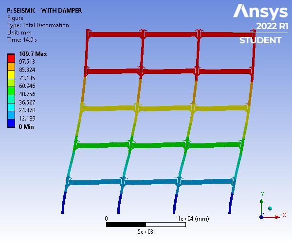
A five storied building frame is modelled in the ANSYS softwarewithdamper.Fig41showsthemodelofabuilding frame with damper. Fig 42 shows the total deformation diagram A loading of Kobe earthquake is applied to the buildingframe.
Fig38.Modelofabuildingframewithoutdamper
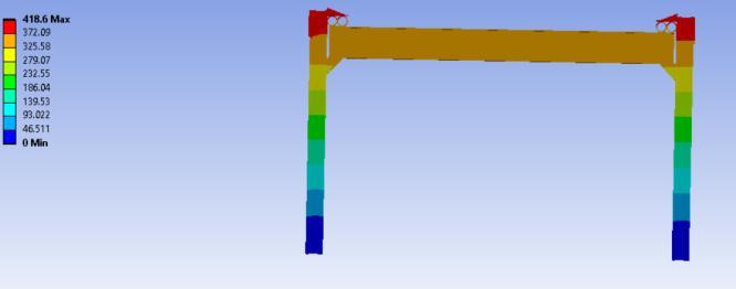
LoadingsuchasKobeearthquakeisappliedtothestructure. Fig 39 shows the Acceleration Time history of Kobe earthquake. Fig 40 shows the deflection of the building frame.
Fig41.Modelofabuildingframewithdamper
Volume: 09 Issue: 07 | July 2022 www.irjet.net p ISSN: 2395 0072 © 2022, IRJET | Impact Factor value: 7.529 | ISO 9001:2008 Certified Journal |
International Research Journal of Engineering and Technology (IRJET) e ISSN: 2395 0056
Volume: 09 Issue: 07 | July 2022 www.irjet.net p ISSN: 2395 0072
Fig42Totaldeformationdiagram
4.3 Results and comparison
Fig43showsthegraphofbaseshearcomparisonofmodel withandwithoutdampers
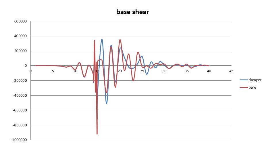
Table2comparisonofbaseshearanddisplacement MODELS DISPLACEMENT (mm) BASE SHEAR(kN)
BAREFRAME 100.95 71643 FRAMEWITH DAMPER 108.18 57967
Thebareframehasadisplacementof100.95mmwhereas theframewithdamperhasadisplacement108.18mm.The bareframehasabaseshearof71643kNwhereframewith damperhasabaseshear57969kN.
Differentmodelsaresubjectedtoparametricstudy withandwithoutdamperinbeamcolumnjoint.
Byanalysingthemodelwithoutdamper,itshowsa ductilityof4andtheloadcarryingcapacityof1022 kN
Byconductingparametricstudy,themodelhaving moreductilityandloadcarryingcapacityisselected as effective size (200x15x120). The model with damper shows more ductility and load carrying capacity.
Variousshapesofmodelslikeellipse,oval,xshape, circular is modelled in ANSYS software. From the above models, the circular shaped damper shows moreloadcarryingcapacityandductility.
Low yielding materials used in modelling of dampers.Bymodellingdamperswithlowyielding material,circulardampershowsmoreloadcarrying capacityandductility.
Time history analysis is carried out in multi storeyedbuildingframe.5storiedbuildingframes with and without damper is analysed in the software.Dampersareinstalledinthebeamcolumn jointoftheframe.Themodel withdampershows moredisplacementthanthebareframe.Thebare frameshowsmorebaseshearthanthemodelwith damper.ie,themodelwithdampershowslessbase shearthanbareframe.So,theforcescominginto thebuildingreducesto19%.
Hence conclude that stability of the building increases when circular dampers are installed in beam column joint of a multi storeyed building frame.
[1].SilviaCostanzo,MarioD’Aniello⁎,Raffaele
Landolfo “The influence of moment resisting beam to column connections on seismic behavior of chevron concentricallybracedframes”JournalofConstructionalSteel Research188(2022)107057
[2].OnurSeker “Seismic response of dual concentrically braced steel frames with various bracing configurations” JournalofConstructionalSteelResearch188(2022)107057
[3].AmirMasoumiVerki,AdolfoPreciado“Experimentaland analyticalinvestigationsofenhancedsemi rigidconnections withdualpipedampers”Structures33(2021)3765 3778
[4].HaifengBu,LiushengHe ,HuanjunJiang“Studyonsteel slit shear walls with different characteristics of hysteretic behavior”Thin walledstructures128
[5].MohammadMahdiJavidana,SeunghoChunbandJikoo Kim “Experimental study on steel hysteretic column dampers for seismic retrofit of structures” Steel and CompositeStructures,Vol.40,No.4(2021)495 509
6].JiaZheng,ChunweiZhang“ExperimentalInvestigationon theMechanicalPropertiesofCurvedMetallicPlateDampers” Appl.Sci. 2020,10(1),269.
[7].Ali Ashasi Sorkhabi ,AmirrezaGhaemmaghami , OyaMercan“Experimental investigationsoftunedliquid damper structure interactions in resonance considering multipleparameters”JournalofSoundandVibration
[8].Rongqian Yang 1 and Xuejun Zhou 2 “Experimental ResearchandTheoreticalAnalysisoftheSeismicBehaviorof PrefabricatedSemirigidSteelFramewithX ShapedBraces” LatinAmericanJournalsofSolidsandStructures
[9].WeiGuo,XingyeWang ,YujieYua,XueyuanChena,Shu Li a , Wenbin Fang , Chen Zeng , Yang Wang , Dan Bu “ExperimentalstudyofasteeldamperwithX shapedwelded pipe halves” Journal of Constructional Steel Research170(2020)
International Research Journal of Engineering and Technology (IRJET) e ISSN: 2395 0056 Volume: 09 Issue: 07 | July 2022 www.irjet.net p ISSN: 2395 0072 © 2022, IRJET | Impact Factor value: 7.529 | ISO 9001:2008 Certified Journal