1,2
International Research Journal of Engineering and Technology (IRJET) e ISSN: 2395 0056

Volume: 09 Issue: 08 | Aug 2022 www.irjet.net p ISSN: 2395 0072
1,2
International Research Journal of Engineering and Technology (IRJET) e ISSN: 2395 0056
Volume: 09 Issue: 08 | Aug 2022 www.irjet.net p ISSN: 2395 0072
3,4,5,6
Abstract To build a 3D virtual model of an aircraft by modelling in the MATLAB Simulink. The Simulink model consists of the circuit model of aircraft containing its design parameters nested in the model containing input for control deflections and atmospheric variables. Mean Sea Level Conditions used here, with the assumption of aircraft flying near sea level. The first aim was to generate the graphs of changes in translational velocities, rotational velocities and Euler angles with respect to time, corresponding to a cruising aircraft with specified deflection of a single controlsurfacefor an interval of 5 seconds after which the control surface was brought back to original configuration. The results of the graphs werwe compared with the results of an ideal case obtained from solving the equation of motion of an aircraft. The database of information regarding the changing parameters acts as a feed to the circuitry containing the virtual model. 'Aeroblk_HL20' was the virtualaircraftusedfor animation. The values of aircraftorientationparametersafter computation goes to 'Aeroblk_HL20' which changes its attitude and position accordingly. The position of the aircraft has been tracked using non inertial North East Down system in which the origin was fixed at the Centre of Gravity of aircraft and its axes were oriented along the geodetic directions as defined by the earth surface. The behaviour of aircraft in animation was in accordance with the ideal values obtained from graphs for the given condition.Thisverification thus proves the efficiency of the virtual tool built. This tool bridges the gap between the myriad of aircraft orientation data and the simulation of an aircraft in flight.
On December 17, 1903, Wright brothers invented aircraft controls makingfixed wing powered flight possible.Their fundamentalbreakthroughwastheinventionofthree axis control, enabling the pilot to control the aircraft and maintain its equilibrium. With the advancement and development in aircraft sector it becomes mandatory for controlengineerstoinvestigatethestabilityoftheaircraft. Aircraft and missiles are usually equipped with a control system to provide stability, disturbances rejection and referencesignaltracking.Themotionofanaircraftinfree flightisextremelycomplicated.Thecontroltheoryforthe
***
samehastwoapproaches[1].Thefirstapproachisbasedon frequency response methods, the root locus technique, transferfunctions,andLaplacetransforms.Thisapproachto controltheoryissometimescalledclassicalorconventional controltheory.Amajorfeatureoftheseanalysismethodsis theiradaptabilitytosimplegraphicalprocedures.Withthe advent of high speed digital computers, control system analysis methods are developed based on the state space formulation of the system. These analysis techniques, developed since the 1960s, are commonly called modern control theory [2]. With the state space formulation and usage of graphic tools, it becomes easier to simulate an aircraft in flight and also to keep a check on the control parametersof theaircraft. Suchabilities arecrucial inthe design and working of automatic flight controller and workingofautopilot.Sperry brothersarethedesigners of thefirstautomaticflightcontroller.Thisinventionchanged thewholeaircraftmanufacturingsectorandalsoboostthe invention of other technologies like, aerodynamics, structures, materials, population and flight control [3]. As per the objective of this paper, a simple simulation tool is designedasthebaseforconvertingnumericdataintovirtual model. This basic tool, upon further modification can be helpful in understanding and designing of Flight Control Systems.Ambitiousaircraftprogramsandtoughcompetition betweenmanufacturershelpsstrivetowardsFlightControl System (FCSs), to provide improved and efficient performance [4]. Generally, aircraft contains three translationmotions(vertical,horizontalandtransverse)and threerotationalmotions(pitch,yawandroll)bycontrolling aileron, rudder and elevator. To reduce the complexity of analysis,theaircraftisusuallyassumedasarigidbodyand aircraft’s motion consist of a small deviation from its equilibriumflightcondition[5]
An aircraft in flight is free to rotate about the three axes, namely,vertical,lateralandlongitudinal.Themomentsabout theseaxesarecalledyaw,pitchandrollrespectively.These axesmovewithvehicleandrotaterelativetotheearthalong withtheaircraft.TheyawaxispassesthroughC.G.ofaircraft andisperpendiculartothewingsandfuselagereferenceline. Itisdirectedtowardsthebottomoftheaircraft. Apositive yawing motion moves the nose of the aircraft to the right. Thepitch axisor transverseorlateral axis passes through
International Research Journal of Engineering and Technology (IRJET) e ISSN: 2395 0056
Volume: 09 Issue: 08 | Aug 2022 www.irjet.net p ISSN: 2395 0072
C.G.ofaircraftandisdirectedtotheright,paralleltoaline drawnfromwingtiptowingtip.Apositivepitchingmotion raises the nose of the aircraft and lowers the tail. Theroll axisorlongitudinalaxispassesthroughC.G.andisdirected forward,parallel tothefuselagereference line.Anangular displacementaboutthisaxisiscalledbank.Apositiverolling motionliftstheleftwingandlowerstherightwing.These momentsaboutprincipleaxesaregeneratedbythedeflection ofthreeprimarycontrolsurfaces,whichvarythepressure distributionoverthesurface,thusvaryingthenetforceabout aircraft’sC.G.
TheprincipleforcesactingonanaircraftinflightareLift force,Dragforceandthemomentsduetothesame.Liftcan bedefinedasthenormalcomponentoftheresultantforce thatisresponsibleforflyingoftheaircraft.Thedragforceis thehorizontalcomponentoftheresultantforce,oppositeto the direction of motion, that provides resistance to the motionofaircraftinair.Theliftanddragforcesactthrough the aerodynamic centre of the aircraft. The engine forces provideforwardthrusttotheaircraft.Theseforcesgenerate moments about C.G., whose magnitude is dictated by the magnitudeoftherespectiveforcesandtheirdistancefrom theC.G. Lift
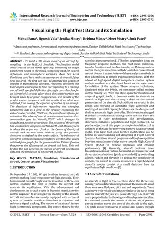
MATLAB is a programming and numeric computing environmentusedbymillionsofengineersandscientists to analyse data, develop algorithms, and create models. MATLAB provides professionally developed toolboxes for signal and image processing, control systems, wireless communications, computational finance, robotics, deep learning and AI and more. MATLAB combines a desktop environment tuned for iterative analysis and design processes with a high level programming language that expressesmatrixandarraymathematicsdirectly.Theaircraft modelusedunderthisprojectisa6 DOFRCAM(Research CivilAviationModel)[1].Theaimistomodelthestatevectors andcontrolvectorsofthisaircraftaswellasthechangein them in the form of state derivatives. There are 12 state vectorsand5controlvectors.Thestatevectorsconsistof3 translationalvelocities,3rotationalvelocities,3Eulerangles and3directions(i.e.,positionNorth,positionEast,position Down). The control vectors are deflections in Aileron, Elevator, Rudder, throttle 1 and throttle 2. The maximum deflectionsofcontrolsurfacesandthrottleissetwhichalso limits the values of control vectors. The maximum and minimumdeflectionforaileronis+25and 25,forelevatorit is+10and 25,forrudderitis+30and 30,forboththrottles itis0.5and10respectively.
Amulti domainmodellingandsimulationenvironmentfor engineersandscientistswhodesigncontrols,wireless,and otherdynamicsystems.WithSimulink,youcandesignand simulatesystemsbeforemovingtohardware,andyoucan exploreandimplementnewdesignswithouthavingtowrite C, C++, or HDL code.Simulink is the platform for Model BasedDesignthatsupportssystem leveldesign,simulation, automatic code generation, and continuous test and verificationofembeddedsystems.
Keycapabilitiesinclude:
Agraphicaleditorformodellingallcomponentsofa system.
Alibraryofprebuiltblocksformodellingalgorithms andphysicalsystems.
Large scalemodellingblocksforcreatingreusable systemcomponentsandlibraries.
AsimulationenginewithODEsolversforverifying thatallpartsofsystemworktogether.
International Research Journal of Engineering and Technology (IRJET) e ISSN: 2395 0056
Volume: 09 Issue: 08 | Aug 2022 www.irjet.net p ISSN: 2395 0072
Visualization tools for analysing and comparing resultsfrommultiplesimulations.
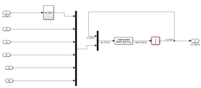
ThecompleteSimulinkmodelusedisasbelowinFig 1and Fig 2:
direction of the oncoming air. The difference in these directionsistheAngleofAttack.So,parametersaredefined intermsofaslightlymodifiedaxissystemcalled"stability axes". The stability axis system is used to get the X axis aligned with the oncoming flow direction. Essentially, the body axis system is rotated about the Y body axis by the trimAngleofAttackandthen"re fixed"tothebodyofthe aircraft. Engine forces for both the engines calculated initially using the Newton’s Second law according to the throttlesettingandthenitdefinedinthebodyaxissystem.
ThefinalinputintotheMATLABcreatedfunctioninvolves calculationofthetranslational,rotationalvelocitiesandthe Eulerangles.Thefirst9statevectorscalculatedasfollows:
Fig 1:Completesimulationmodel
;whereFb isthesummationofgravityforce,engineforces andaerodynamicforces.
Rotation of parameters in body frame to aircraft carried North,EastandDownframebysuitableEulerangleshelpin determining position of aircraft w.r.t earth Aircrafts usea coordinatesystemofaxeswhichhasitsoriginastheCentre ofGravityoftheaircraft.Twoslightlydifferentalignmentsof theseaxesareuseddependingonthesituation:“bodyfixed axes”and“stabilityaxes”.Bodyfixedaxesdefinedandfixed relativetothebodyofthevehicleasfollows:
X bodyaxisisalongthevehiclebodyandispositive towardsthenormaldirectionofmotion.
;whereMCG isthesummationofmomentaboutCGdueto engineandaerodynamicmomentsaboutCG.Ibistheinertia matrix.
Y body axis is at right angle to X body axis and is oriented along the wing. The Y axis is usually positivetotherightsideofvehicle.
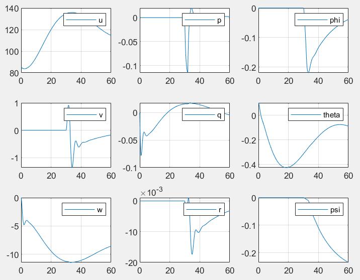
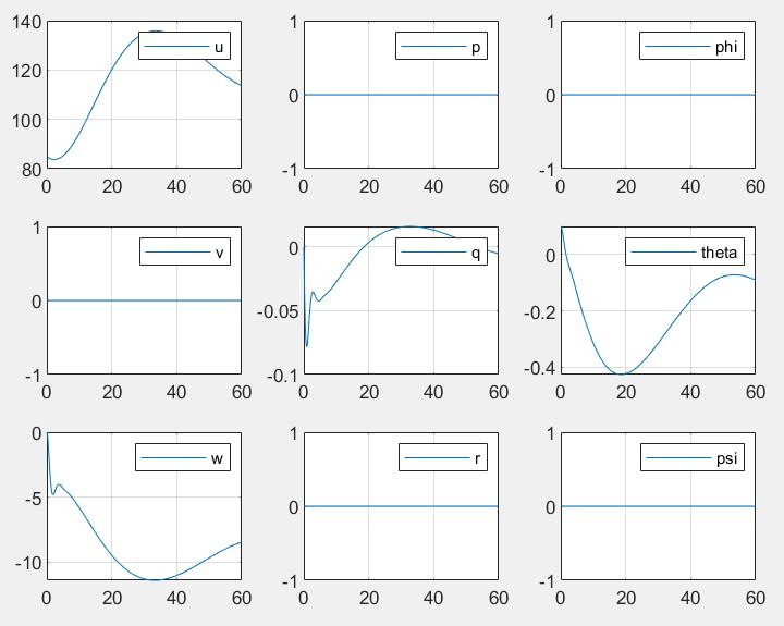
The aircraft flying at a speed of 85 m/s with all control surface deflections at zero. The throttles set at minimum condition required for flying for RCAM model. The initial position of aircraft according to [PN, PE, PD] is kept at [ 12000, 1000, 4000] The‘.m’fileisrunforatimeperiodof 60secondsandtheresultsaregeneratedasshowninFig 3 Theaircraftflyingataspeedof85m/s.Thedeflectionfor rudder and elevator is kept at zero while the ailerons deflected at time t=30 seconds for about 2 seconds by an angle of 5 degrees and then brought back to normal. The throttles setatminimumconditionrequiredforflyingfor RCAMmodel.Theinitialpositionofaircraftaccordingto[PN, PE,PD]iskeptat[ 12000, 1000, 4000]
Z body axis is perpendicular to wing body (XY) planeandusuallypointsdownwards.
Aircraft operates at constant "trim"Angle of Attack. The angle of the nose (the X Axis) does not align with the
The‘.m’fileisrunforatimeperiodof60secondsandthe resultsaregeneratedasshowninFig 4
International Research Journal of Engineering and Technology (IRJET) e ISSN: 2395 0056
Volume: 09 Issue: 08 | Aug 2022 www.irjet.net p ISSN: 2395 0072
intermsofaslightlymodifiedaxissystemcalled"stability axes".
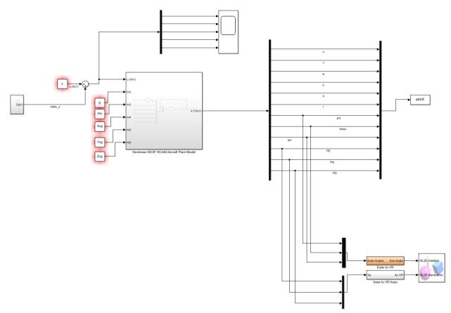
The virtual model of aircraft with position and direction indicated in bottom right corner as shown in Fig 4. This modelwastakenfromtheinbuiltmodelof“aeroblk_HL20” present in the MATLAB environment. Aerodynamic force coefficient matrix formed which consists of 3 elements namely,rollcoefficient,pitchcoefficientandyawcoefficient. Moment and forces considered along body axis and about theaerodynamiccentreofaircraft.Theaerodynamicforces arecalculatedfromtherespectiveforcecoefficients.These forces are primarily in stability axis system. They are converted into the body axis system by rotating them by specificangles.Aircraftoperatesataconstant"trim"Angleof Attack.Theangleofthenose(theXAxis)doesnotalignwith the direction of the oncoming air. The difference in these directionsistheAngleofAttack.So,parametersaredefined
The results from graphical representation of various coordinates and angles from the scope used in the block diagramofSimulink.Deflectingtheaileroncontrolandgot the graphical representation for different variables. Upon deflectingtheaileronby5degrees,thereisapeakobserved inthegraphindicatingrotationaboutxaxisi.e.,thevalueof 'p'.Afterdeflectingitthedipobserved.Thisshowsthatthe aircrafthasundergonerollingwhichisshownbychangesin the graphs of 'p' and 'phi'. The graphs obtained from the virtual model in the MATLAB Simulink are in accordance withtheactualresultsobtainedfromtheaircraftflyingwith ideal condition. This proves the efficiency of the model developed. This model helps in better understanding of control&navigationofaircraftsandmissilesbytheusageof 3 dimensionalmodelview.Itactsasabridgebetweenthe theoreticalunderstandingandthepracticalapplication.Even though this model is based upon the ideal conditions of atmosphere, modelled for sea level conditions, it can be furthermodifiedtosimulatethereal lifeproblemwiththe data available from Flight Data Recorder and by usage of atmosphericmodelling.
[1] Robust Flight Control Design Challenge Problem Formulation and Manual: The Research Civil Aircraft Model(RCAM),GARTEUR/TP 088 3,June15,1995.
[2] R. C. Nelson, Flight stability and automatic control, PublishedbyWCB/McGraw Hill,1998.
[3] LucioR.Riberio,NeusaMariaF.Oliveira:“UAVAutopilot ControllersTestPlatformUsingMatlab/SimulinkandX Plane”, 40th ASEE/IEEE Frontiers in Education Conference,October27 30,2010,Washington,DC.2010.
International Research Journal of Engineering and Technology (IRJET) e ISSN: 2395 0056 Volume: 09 Issue: 08 | Aug 2022 www.irjet.net p ISSN: 2395 0072
[4] Omur Akyazi,A.SefaAkpinarandM. AliUsta:“A self tuning fuzzy Logic Controller for aircraft roll Control System”, International Journal of Control Science and Engineering.2012.
[5] J.K. Shiau, D.M. Ma: “An Autopilot Design for the Longitudinal Dynamics of a Low Speed Experimental UAV using Two Time Scale Cascade Decomposition”, Transaction of the Canadian Society for Mechanical Engineering,Vol33,No3,2009.
[6] Ye, G. & Tian, Z. & Yan, C.. (2011). Flight test data visualizationofaircraft'sflightcoursebasedonOpenGL. 32.1050 1057.
[7] Li, W. & Yan, C. & Tian, Z. & Meng, Q.. (2012). Data visualizationofaircraftloadspectrumbasedonVC++. 32.458 461.
[8] Tian, Z. & Yan, C.. (2015). Design of visual simulation systemofaircraftflightload spectrummeasureddata basedondouble bufferingtechnology.BeijingHangkong HangtianDaxueXuebao/JournalofBeijingUniversityof AeronauticsandAstronautics.41.431 436.