International Research Journal of Engineering and Technology (IRJET) e ISSN: 2395 0056

Volume: 09 Issue: 07 | July 2022 www.irjet.net p ISSN: 2395 0072
International Research Journal of Engineering and Technology (IRJET) e ISSN: 2395 0056
Volume: 09 Issue: 07 | July 2022 www.irjet.net p ISSN: 2395 0072
1Lecturer, Mechanical Engineering, GPT, Arakere, Mandy Dist, Karnataka, India 2Lecturer, Mechanical Engineering, GPT, Mirley, Mysuru Dist, Karnataka, India 3Lecturer, Mechanical Engineering, GPT Belagavi, Karnataka, India ***
Abstract In this study, efforts were made to study the effect of profile modification on the vibratory behaviour of standard and profile modified spur gears. Profiles have been modified by the disposition of an addendum with a suitable modification factor. TheFiniteelementmethodisusedtocarry out modal analysis of standard and profile modified spur gears. Ansys Workbench v.17 is used as finite element software. Vibratory behaviour has been studied in terms of modal. It is shown that profile modified spur gearshavebetter vibratory behaviour compared to standard gears.
Key Words: Standard gear, spur gear, profile modification, modal analysis, Profile modified spur, Vibration analysis, Modification factor, Natural frequency, finite element, Ansys.
GEARS,ortoothedwheels,arethebasicmachineelements thattransmitmotionandpowerbysuccessiveengagementof teeth on their periphery. They constitute an economical methodforsuchtransmission,particularlyifpowerlevelsor accuracy requirements are high. Gears are an important elementinalltypesofmachinery.Applicationsofgearsare diverse,like automobiles, aerospace,agriculture, precision equipment,robots,machinetools,etc.
Spurgearsareusedtotransferlowandmediumpower betweentwoparallelaxes.Thedisadvantageofspurgearis that more operating sound will be produced at a higher operatingspeed.Gearstransmitpowerduetomeshingaction betweenthegears.Themeshingactionofgearsoccursdueto rollingandslidingactionbetweenthegears.Generally,gears failduetowear,scoring,fatigue,corrosion,spalling,pitting, and interference. This results in alteration of profile modificationofteethandbecomesasourceforthevibration of gears. Hence, it is necessary to study the profile modification of gears to minimise the vibration and give directcontroloverthefailureofgears.
The main purpose of the gear tooth profile is to transmit power constantly from one shaft to another through the conjugateactionofgearteeth.Theinvolutetoothprofileis commonlyusedbecauseofitsvariousadvantages.Themain sourceofvibrationofthegearisfromtheprofileofthegear tooth, and vibration may increase or decrease due to
modificationoftheprofile.Corrosion,pitting,wear,scuffing, etc.,willalsoincreasevibrationingears.
Spur gears have their teeth parallel to the axis and are usedfortransmittingpowerbetweentwoparallelshaftswith a basic rack of standard gears having an equal amount of tooth thickness and tooth space on the pitch circle. For standardgears,thereisnoprofilecorrectionandtheradius ofcurvatureoftheinvoluteattherootiszero.Thepressure angleforstandardgearsmayvaryfrom14.5˚to20˚,etc.,and theteethmaycomeintheformoffull depthorstubtooth systems.The20˚fulldepthinvolutesystemiswidelyused.
Vibration is a virtual property of the system when it is subjected to dynamic loads.A spur gear isa geometrically symmetricstructure,andeachtoothisasubstructureofthe gear. Loading on spur gear is unsymmetrical, resulting in unbalanced forces that lead to vibration [1]. The non conformity of the tooth profile while manufacturing gear resultsinvibrationofthegear.
Hence, vibrationanalysis vibration ofspur gear isvery important and it has to be minimised before the actual working environment for long service. Modal analysis, harmonic analysis, and transient analysis are the types of vibrationanalysis.Modalanalysisisthefreevibrationofthe gears under no load conditions. This analysis will give the naturalfrequencyandmodeshapesofgearteeth.
Byalteringtheprofileofthegear,thevibrationofthegear behaviourcanbealtered.Therearemanymethodsofprofile modification, like linear profile modification [2], parabolic profilemodification[3],toothleadcrownrelief,andprofile shiftmodification[4].Profileshiftmodification,alsoknown asaddendummodification,involvesdispositionofaddendum anddedendumrelativetothepitchcircleonbothpinionand gear by selecting the portion of the involute with a larger radiusofcurvaturewithasuitablemodificationfactor.
A profile modification factor is a fraction related to theselectedgearmodule.Positiveprofilemodificationmeans shiftingofthetoothprofileawayfromthecentreofthegear
International Research Journal of Engineering and Technology (IRJET) e ISSN: 2395 0056
Volume: 09 Issue: 07 | July 2022 www.irjet.net p ISSN: 2395 0072
andnegativeprofilemodificationmeansshiftingofthetooth profiletowards the centre of the gear. The positive profile modificationwillhavealargertooththicknessonthepitch circle,andthenegativeprofilemodificationwillhavemore toothspaceonthepitchcircle.
Therearetwotypesofprofileshiftmodification,i.e.,SO andSgearsystems.ForSogeargearingsystems,thesumof themodificationsonbothpinionandgearmustbeequalto zero,whichmeansonegearwithpositiveandtheotherwith negativeprofilemodificationtobedone.Hence,thecentre distance will be constant. The S gear system of profile modification must have a positive or negative sum of modificationfactorsonboththepinionandthegear[5].
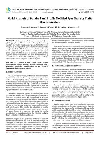
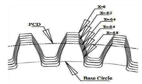
Figure1representsthenatureoftheinvolutesofacircle. Inastandardpinion,theradiusofcurvatureofinvolutesat rootiszeroandwillhaveadefiniteradiusofcurvatureatthe tip circle diameter. Figure 1.2 distinguishes the curvature radius at the tip circle diameter for standard and profile modified gears. The increase in the profile shiftcoefficient yieldsa specific portion of involute witha larger radius of curvature.
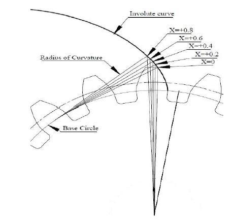
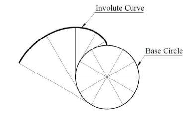
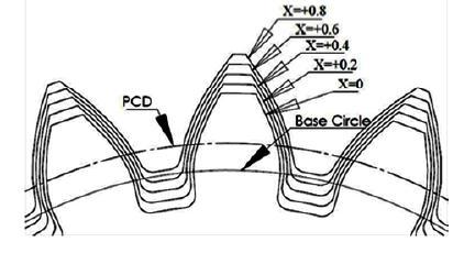
Figure 3 and 4 gives information on addendum modificationwithsuitablemodificationfactorforbothpinion and gear. Profile modifications also have the following advantages.Positivelycorrectedpinionswillhaveanincrease inthestrengthattherootofthepinionastooththicknesson thepitchcircleisincreased,slidingandcontactrelationsare improved, and contact stresses are decreased, resulting in bettersurfacedurability.
Fig 1: Involuteofacircle
Fig 2: Involutecurvewithdifferentmodificationand radiusofcurvature
Fig 3: Addendummodifiedpinionwithpositive(+)profile modification
Fig 4: Addendummodifiedgearwithnegative( )profile modification
Thefollowingmainpapershavebeengonethrough,and abriefoverviewofthosepapersisgivenhere.S.S.Ghoshand G. Chakraborty [2] have studied the effects of gear tooth profilemodificationontheoveralldynamicsofaspurgear system. They have been studied with the objective of achievingthebestprofilewhichwillleadtoalowvibration level.
HsiangHsiLin[3]hasstudiedtheeffectoftoothprofile modification on the dynamic performance of spur gear systems. Parabolic tooth profile modification is generally preferredforlowdynamicresponseingear, whichoperates atlowoperatingoverrangeofloadingconditions.
International Research Journal of Engineering and Technology (IRJET) e ISSN: 2395 0056
Volume: 09 Issue: 07 | July 2022 www.irjet.net p ISSN: 2395 0072
The author, Hui Man [5], has carried out a study on optimum profile modification. Based on a mesh stiffness modelofprofileshiftedgearswithaddendummodification andtoothprofilemedications(TPM)proposedinthispaper, time varying mesh stiffness (TVMS), load sharing factor (LSF),loadsharingandtransmissionerror(LSTE),andnet loadsharingandtransmissionerror(NLSTE)oftheprofile shiftedgearwithdifferentamountsofprofilemodification corresponding to four types of profile modification are analyzed.
ZehuaHu[5],focusesontheanalysisoftheeffectsofthe tooth profile modification on the dynamic responses of a high speedgear rotor bearingtransmissionsystem.
The authors M. Divandari [6] and others discuss the effectsoftoothprofilemodificationanditseffectsonthegear pairvibration.Theyhavetriedtoconcludeeffectonlocalized toothdefectsduetotoothprofilemodificationbycalculating toothmeshstiffness.Themeshstiffnessofgearteethvaries duetothechangesintheprofileofgearteeth.
Basedontheabove,theproblemforthisworkisdefined as "Modal Analysis of Standard and Profile Modified Spur GearsbyFiniteElementAnalysis."
To realise the objectives outlined above, the following methodologyhasbeenadopted.
1. Estimation of the module using Lewis theory and determiningthedimensionsofstandardandprofilemodified spurgearforaspecificloadingcondition.
2.Geometricmodellingofstandardandprofile modifiedspur gears
3. Modal analysis of the gear tooth by using the Finite ElementMethod(FEM)
4. Comparison of modal analysis results of standard and profile modifiedspurgear
Modalanalysisistheundampedfreevibrationofthesystem toknowthedynamiccharacteristicsofthesystem.Natural frequency, modal behaviour, and damping coefficients are dynamiccharacteristicsofthesystem.
The methods of determination of natural frequencies for continuous systems are explained here [7]. 1. Mass and stiffness method 2. Rayleigh's method and 3. Numerical (FEM)methodInthiswork,anumericalmethodisadoptedto findthenaturalfrequencyofstandardandprofilemodified spurgearteeth.
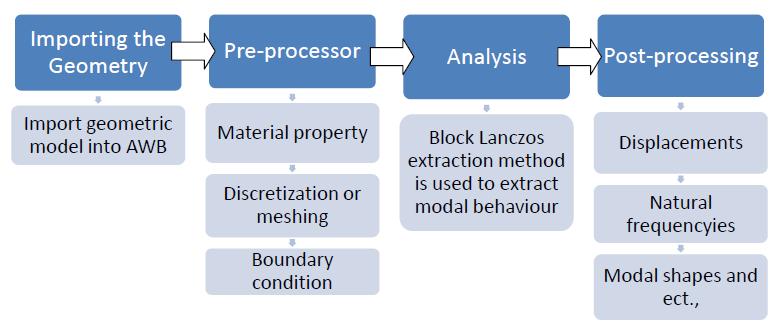
AnalysisworkhasbeencarriedoutinAnsysWorkbench17.0. These are steps to be followed in any FEM based analysis software,andFigure5showstheflowchartofFEMsteps.
Fig 5: GeneralprocedureformodalanalysisusingFEA
2.2 Modal Analysis of Standard and Profile Modified Pinion
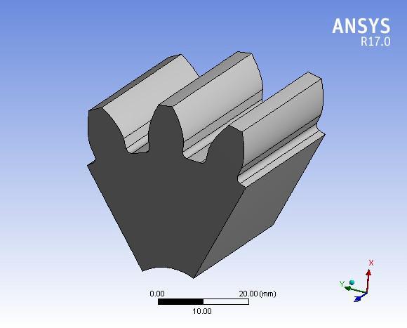
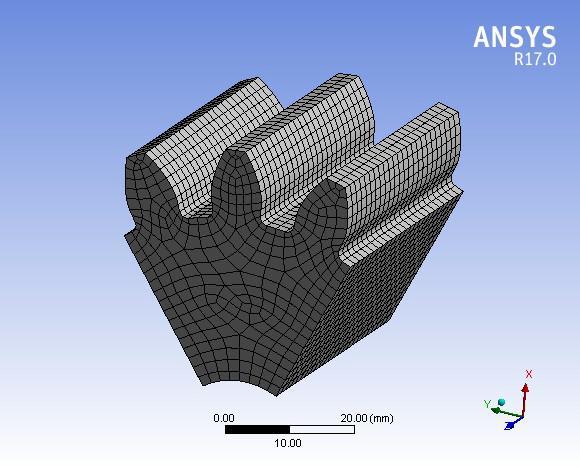
Figure 6. A gear model of pinion consisting of 3 teeth sections subtended by an angle of 60 degrees is shown in Figure6.Thetotalnumberofteethis18,withamoduleof5 mm.Thethree toothmodelisconsidered[6]forthemodal analysisbecausethegearhasacyclicallysymmetricstructure andeachtoothisasub structureofthegear.Onetoothmay beconsideredforanalysisandappliedboundarycondition, butitwill notbesimilartotheactual one.Hence,adjacent teetharealsoconsideredfortheanalysis.Theboundariesof adjacent teeth are constrained. Thus, displacement of the centraltoothwillbethesameasinactualgear.
Fig 6: PinionmodelforFEManalysis.
International Research Journal of Engineering and Technology (IRJET) e ISSN: 2395 0056
Volume: 09 Issue: 07 | July 2022 www.irjet.net p ISSN: 2395 0072
The imported solid model has been divided into small elements,asshowninFigure3.3.TheelementtypeSOLID186 willbebestsuitedfortheanalysisofsolidmodelsinAWB. This model consists of 34,760 nodes and 7464 elements. Figure7showsadiscretizedmodelofthepinion.
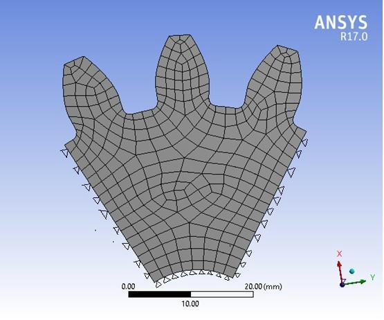
Thetotalanglesubtendedbythethree(3) toothgear sector [7] of the 18 tooth model is about 60 degrees. The followingboundaryconditionshavebeenchosenformodal analysis of standard pinion. A gear is a cyclically (axisymmetric) symmetric mechanical element. Therefore, there will be no deformation in the tangential (rotational) direction. Hence, the outer radial lines of the three tooth sectorsandrimareconstrainedinalldirectionsasshownin Figure3.4.Theteeth'souterandinnersurfaceshavebeenleft untouched.
Theresultsofnaturalfrequenciesofmodalanalysisaregiven inTable1.Thenaturalfrequenciesofthefirstsixmodesof vibrationaretabulatedbecausethefirstmodeanduptothe thirdmodeofvibrationcanbeobservedinpractisewhilethe rest of the modes of vibration cannot be observed due to modesuperposition[7].InTable3.1,X=0,X=+0.2,andso onrepresenttheprofilemodificationfactor,and1,2,andso on represent the number of vibration modes. Each cell representsthenaturalfrequencyofmodesofvibrationwitha correspondingmodificationfactorX.
Table 1: Naturalfrequencyofthestandardandprofile modifiedpinion
Mode Numb er
X=0 X=+0.2 X=+0.4 X=+0.6 X=+0.8
1 31489 31281 31178 31107 31029
2 33197 35580 37865 39770 41209
3 34797 37591 40236 42074 43243
4 35022 37745 40369 42557 43300
5 37916 39924 41490 42800 44807
6 39627 42038 44318 46413 48222
Fig 7: Discretizedmodelofpinion
The variation of the first six natural frequencies for standard and profile modified pinions with different modification factors X is shown in chart 1. The natural frequencies(NFs)ofstandardpinionsarelowerthanNFof profile modifiedpinions.TheNFsofprofilemodifiedpinions increase as the profile modification factor increases. As observed in geometric modelling, the width of the pinion toothincreasesatpitchcirclediameter.Duetothis,theNFsof profilemodifiedpinionincreasesasthemodificationfactor increases.
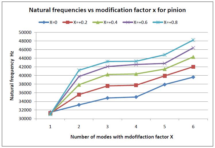
Fig 8: Boundaryconstrainedmodelofstandardpinion
Chart -1:VariationofNaturalfrequenciesforpinionwith modificationfactorX
International Research Journal of Engineering and Technology (IRJET) e ISSN: 2395 0056
Volume: 09 Issue: 07 | July 2022 www.irjet.net p ISSN: 2395 0072
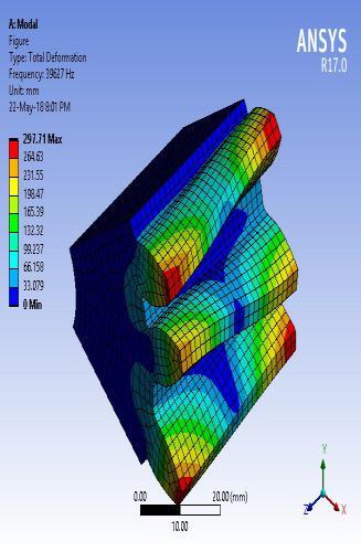
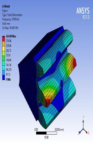
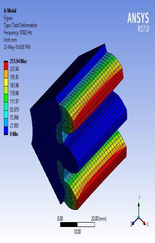
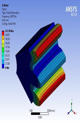
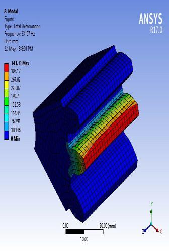
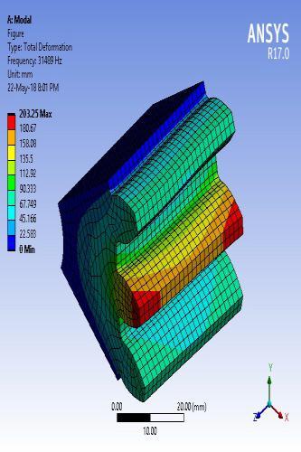
Themodalbehaviourofaprofile modifiedpinionremainsthe same as a standard pinion.Brief discussions on the modal behaviourofstandardpinionteetharepresentedhere.The firstmodeofvibrationoccursatanaturalfrequencyof31849 Hz.Apiniontoothvibratesinanaxialdirection.Thesecond modeofvibrationoccursatanaturalfrequencyof33197Hz. Pinion tooth bending occurs in a tangential direction. The third mode of vibration occurs at a natural frequency of 34797 Hz. The bending of adjacent teeth occurs with the sameamplitude in the opposite directiontangential to the pinionaxisofrotation.Thefourthmodeofvibrationoccursat a natural frequency of 35022 Hz. The bending of adjacent teethoccurswiththesameamplitudeinthesamedirection radial to the pinion axis of rotation. The fifth mode of vibration occurs at a natural frequency of 37916 Hz. The twistingpinionstootheachotherinthesamedirectionalong theaxisofrotationpinion.Thesixthmodeofvibrationoccurs at a natural frequency of 39627 Hz. The twisting pinions tooth each other in opposite directions along the axis of rotationpinion.Thefirstsixmodesofvibrationpinionare showninfigure9.
Fig - 9: Firstsixmodalbehaviourofstandardpinion 2.6 Natural Frequencies of Standard and Profile Modified Gear
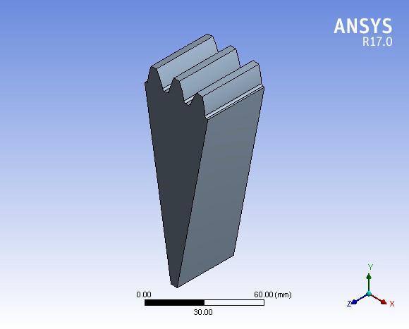
Figure 10. A gear model of pinion consisting of 3 teeth sections subtended by an angle of 20 degrees is shown in Figure10.Thetotalnumberofteethis54withamoduleof5 mm.Thethree toothmodelisconsidered[7]forthemodal analysisbecausethegearhasacyclicallysymmetricstructure andeachtoothisasub structureofthegear.Onetoothmay beconsideredforanalysisandappliedboundarycondition, butitwill notbesimilartotheactual one.Hence,adjacent teetharealsoconsideredfortheanalysis.Theboundariesof adjacent teeth are constrained. Thus, displacement of the centraltoothwillbethesameasinactualgear.
Fig 10: Importedmodelofthreeteethstandardgear. The model has been discretized and boundary conditions have been applied as in the case of pinion. The results of natural frequenciesofmodal analysisstandardandprofile modifiedgeararegiveninTable2.Thenaturalfrequenciesof thefirstsixmodesofvibrationaretabulatedbecausethefirst modeanduptothethirdmodeofvibrationcanbeobserved inpractisewhiletherestofthemodesofvibrationcannotbe observedduetomodesuperposition[7].InTable2X=0,X= 0.2,etc.,representsthenegativeprofilemodificationfactor
International Research Journal of Engineering and Technology (IRJET) e ISSN: 2395 0056
Volume: 09 Issue: 07 | July 2022 www.irjet.net p ISSN: 2395 0072
and1,2,3etc.,representsthenumberofmodesofvibration. Each cell represents the natural frequency of modes of vibrationwithacorrespondingmodificationfactorX.
0
0.2
0.4
Table 2: Naturalfrequencyofthestandardandprofile modifiedgear Mode numbe
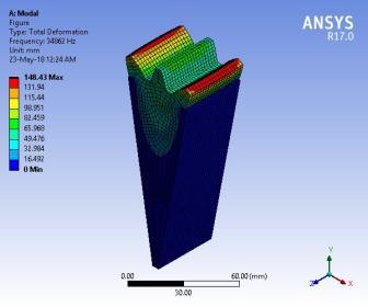
1 27823 27985 28015 28174 28213 2 34862 34885 34556 34266 33463 3 38169 38165 36631 35520 34008 4 41515 41065 39550 38274 36376 5 41572 41611 41387 40765 39188 6 42023 41968 41485 40914 39878
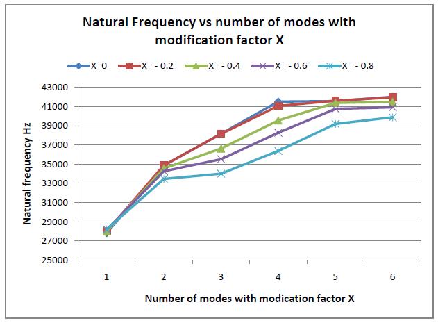
Thevariationofthefirstsixnaturalfrequenciesforstandard andprofilemodifiedgearwithdifferentmodificationfactors X is shown in chart 2. The natural frequencies (NFs) of standardgeararehigherthantheNFofprofilemodifiedgear. TheNFsofprofilemodifiedpinionsdecreaseastheprofile modification factor increases. As observed in geometric modelling, the width of the gear tooth decreases at pitch circlediameter.Duetothis,theNFsofprofilemodifiedpinion decreasesasthemodificationfactorincreases.
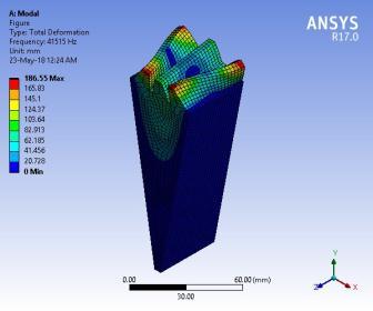
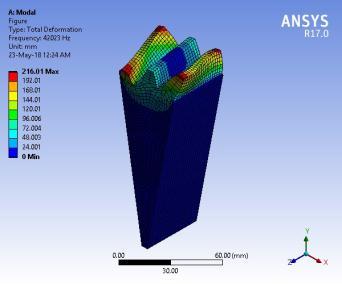
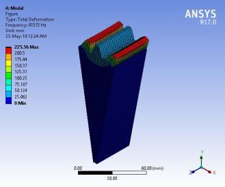
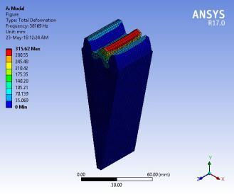
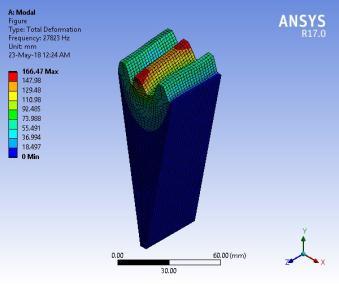
Theresultofthefirstsixmodalbehaviourofstandardgearis showninFigure11.Themodalbehaviourofprofile modified gearremainsthesameasstandardgear.Hence,themodal behaviourofstandardgearispresentedinthiswork.Brief discussionsonthemodalbehaviourofstandardgearteeth arepresentedhere.Thefirstmodeofvibrationoccursata naturalfrequencyof27867Hz.Gearteethvibrateinanaxial direction.Thesecondmodeofvibrationoccursatanatural frequencyof34862Hz.Thebendingofadjacentteethoccurs withthesameamplitudeintheoppositedirectionradialto thegearaxisofrotation.Thethirdmodeofvibrationoccurs at a natural frequency of 38169 Hz. Gear tooth bending occursinatangentialdirection.Thefourthmodeofvibration occursata natural frequencyof41515Hz.Thebendingof adjacent teeth occurs at the same amplitude in the same direction tangential to the gear axis of rotation. The fifth modeofvibrationoccursatanaturalfrequencyof41572Hz. The twisting gears tooth each other in the same direction along the axis of the rotation gear. The sixth mode of vibration occurs at a natural frequency of 42023 Hz. The twistinggearstootheachotherinoppositedirectionsalong therotationgear'saxis.
International Research Journal of Engineering and Technology (IRJET) e ISSN: 2395 0056
Volume: 09 Issue: 07 | July 2022 www.irjet.net p ISSN: 2395 0072
Modal analysis of standard and profile modified pinions (SPMP)andstandardandprofilemodifiedgears(SPMG)has been done. There is variation in natural frequency in both SPMPandSPMGwithrespecttoprofilemodificationadapted (positiveornegative)topinionandgearisshowninFigure 3.12. Natural frequency variation with respect to SPMP is always increased with increasing positive profile modificationfactorXduetoanincreaseinthicknessatthe piniontooth'srootsection.Similarly,asthenegativeprofile modification factor X increases, the variation of natural frequencywithrespecttoSPMGdecreasesduetoadecrease inthicknessattherootsectionofthegeartooth.
Due to the increase in natural frequency of the profile modified pinion with respect to modification factor, the pinioncanoperateathigherspeedsthanthestandardpinion between modification factors of x = +0.2 and x = +0.8. Therefore, optimised profile modification is required for betterperformanceofthegear.
[1] V.RamamurthyandM.AnandaRao:“Dynamicanalysis ofspurgeartooth”,Journalofcomputerandstructures, volume29,No5,pp831 843,1988
[2] S.S.Ghosh⁎,G.Chakraborty:“Onoptimaltoothprofile modificationforreductionofvibrationandnoiseinspur gearpairs”,MechanismandMachineTheory105(2016) 145 163,Elsevier
[3] HsiangHsiLinFredB.OswaldDennisP.Townsend: “Dynamicloadingofspurgearswithlinearorparabolic tooth profile modifications”, Mechanism and Machine Theory Volume 29, Issue 8, November 1994, Pages 1115 1129.Elsevier.
[4] Hui Man, Xu Pang, RanjiaoFeng, BangchunWen:“Evaluation of optimum profile modificationcurvesofprofileshiftedspurgearsbased onvibrationresponses”,MechanicalSystemsandSignal Processing,70 71(2016)1131 1149,Elsevier.
Chart 3:Comparisonofnaturalfrequenciesbetween standardandprofilemodifiedpinionandgearwith differentmodificationfactorX.
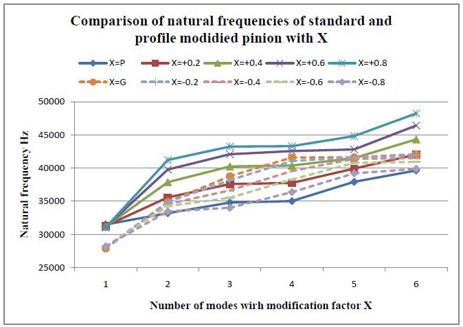
1. Thefollowingpointswereobserved.
2. The natural frequencies of standard pinions are initiallylowerthanthoseofstandardgears,butas the modification factor increases, the natural frequencies of pinions are higher than standard gears.
3. Due to the increased natural frequency of the profile modifiedpinionwithrespecttomodification factor,thepinioncanbeoperatedathigherspeeds thanthestandardpinion.
Natural frequencies of positively corrected pinions increase with increasing modification factor, but they decrease with increasing modification factorof negatively correctedgearteeth.Hence,bothextremeconditionsarenot suitable for practical application because the pinion will haveasharptipandthegeartoothwillbethin.
[5] Gitin M Maitra: “Handbook of Gear Design”, second edition2001, Tata McGrawHill PublishingCompanyLimited,NewDelhi.
[6] M. Divandri, B.H. Aghadam and R. Barzamini: “Tooth Profile modification and its effect on spur gear pair vibrationinpresenceoflocalizedtoothdefect”,Journal ofmechanics,Volume28,pp373 381,2012.
[7] AliRaadHassan:“Transientstressanalysisonmedium modules spur gear by using mode super position technique”, International journal of mechanical and mechatronics engineering, volume 3(5), pp 463 470, 2009.
Prashanth Kumar J. M.Tech(MachineDesign) LecturerinMechanicalDept. GovernmentPolytechnicArakere, MandyaDist,Karnataka,India

International Research Journal of Engineering and Technology (IRJET) e ISSN: 2395 0056
Volume: 09 Issue: 07 | July 2022 www.irjet.net p ISSN: 2395 0072
M.Tech(MachineDesign) LecturerinMechanicalDept. GovernmentPolytechnicMirle, Dist:Mysore,Karnataka,India


M.Sc(Engg)ByResearch LecturerinMechanicalEnggDept, GovernmentPolytechnicBelagavi. Karnataka,India.
2022, IRJET | Impact Factor value: 7.529 | ISO 9001:2008 Certified Journal