International Research Journal of Engineering and Technology (IRJET) e ISSN: 2395 0056

Volume: 09 Issue: 07 | July 2022 www.irjet.net p ISSN: 2395 0072
International Research Journal of Engineering and Technology (IRJET) e ISSN: 2395 0056
Volume: 09 Issue: 07 | July 2022 www.irjet.net p ISSN: 2395 0072
1PG Student, Dept. of Civil Engineering, Ghousia College of Engineering, Ramanagara, Karnataka, India 2Prof & HOD, Dept. of Civil Engineering, Director (R&D), Ghousia College of Engineering, Ramanagara, Karnataka, India ***
Abstract Reliability is the capacity of the structure to satisfy the construction specifications outlined under particular circumstances throughout the service life for which it is intended. Different levels of reliability can be established based on the carrying capacity, serviceability, and durability of the construction. The reliability index is one of the greatest ways to illustratethedegreeofuncertainty in the notion of reliability.The reliabilityanalysisof CFT is conducted in the presentstudybyFOSM(First Order Second Moment) method to clearly understand the impact of the random features of CFT. The definition of the performance functions is based on the numerical modelling of earlier works of literature and statutory provisions. Reliability index is analysed by FOSM for longer columns (L/D > 12) and for shorter columns (L/D < 12). Probability of failure is calculated for different dimensions of both the columns.
Keywords Concrete fil1ed steel tubular (CFST), First order second moment (FOSM), First order Reliability method (FORM), second order Reliability method (SORM).
CFST columns are in great demand in construction work becauseoftheirsmallcross sectionalareatoload carrying capacity ratio. With this great feature, the huge concrete columns in tall structures can be replaced by smaller sectionsofCFSTcolumns.Andalso,forbridgesconstructed inaverycompactarea,CFSTelementscanserveaspiersfor bridges.Buteventhoughsuchstructuralelementsmustbe fully investigated before being used in critical structures, TheCFSTcolumnsexhibitincreasedcompressivestrengthas theycombinetheactionsofthesteeltubeandconcrete.The steelsectionisrestrictedtolocalbucklingbytheconcrete core.ThisCFSTcolumnhasbecomeincreasinglyused.
Composite columns are made up of amalgamation of concreteandsteel,andmakeuseofthebeneficialproperties ofthecomponentmaterials.Useofthis,reducesthesizeof column and gives the premium floor space, which can
ultimately lead to considerable economic savings. A compositecolumnisacompressioncomponentinwhichthe steelandconcreteelementsactinconcert.Theconcretecore in a composite column resists not only compressive pressuresbutalsobucklingofsteelcomponents.
The bond strength in the composite columns plays highly recognisable role in the construction. Bond strength essentiallyinfluencespressure move intheCFSTsegment between the concrete center and steel tube. It likewise assumesasignificantpartinforestallinglimitedclaspingof steeltubes,givinglong lastingformwork,andgivingsteel concrete bond strength, guaranteeing that the two unmistakablepartscooperatetoendurethedifferentoutside loadings of pressure, twist, shear, and bowing second. Accordingly,thestructuralwayofbehavingofCFSTstillup intheairbythebondstrength.
Numerous structural advantages come from the concrete poured inside the hollow steel tubes, including enhanced strength due to concrete confinement, less dead load, material savings, and construction that is simpler and quickerthanusingconventionaltechniques.
Thesteelpipe'scross sectionalform,flatwidth,diameter,or thickness,slendernessratio,concretecorestrength,andthe steel pipe's local buckling behaviour are all contributing elementstotheriseinstrength.
Ahelpfulexplanationofthecompoundactivityofconcrete andsteel isprovidedbythe displayof sectionsunderhub pressure.Thereisaseparationbetweenthesteelwalland the concrete centre because the poisson's proportion for concreteislesserthanthatforsteelduringtheunderlying stages of stacking. According to Furlong [1], the poisson's ratioofconcretesimilarlyriseswiththeload,from0.15to 0.2intheelasticrangeto0.5intheinelasticrange.
Concreteconfinementisthethree dimensionalstressstate thatformsunderanaxialloadandincreasesstrength asa
International Research Journal of Engineering and Technology (IRJET) e ISSN: 2395 0056
Volume: 09 Issue: 07 | July 2022 www.irjet.net p ISSN: 2395 0072
result of the development of radial pressure at the steel concretecontact.
Concrete confinement has a more noticeable effect on circular sections because membrane type buckling causes themtofail,whereasithaslittletonoeffectinrectangular sections.Sincethesteeltubeencirclingtheconcretecorein circular portions acts as lateral restraint, full contact betweenthesteelandconcreteoccurs,increasingstrength. AccordingtoVonMises'yieldcriterion,thisgainoffsetsthe decreaseinsteel'syieldstrengthincompressioncausedby thehooptensionrequiredtoconfineconcrete.Duetoplate buckling,hoopstresscreatedinrectangularportionsvaries alongthesides.Theconfiningeffectislessenedasaresult.
The confinement effect is lessened due to the rise in slendernessalsoincircularsections.
ThestiffnessofCFTcolumnsisdeterminedbytheconcrete's corestrength.Althoughcolumnsthosearefilledwithhigh strengthconcretedisplaybrittlebehaviourandcrushwhen loaded, stiffness rises as concrete core strength increases. Additionally, according to O Shea and Bridge [5], stiffness loss for high strength concrete in filled tubular columns happensquicklyandoccasionallywithaxialstrainreversal. Butitisatruththatfilledcolumnsbecomehighlystrongtoa greaterextentasthestrengthoftheconcretecorerises.
Thepotentialthatasystemorcomponentwillcarryoutits intendedperformancecorrectlyforapredeterminedamount oftimeunderpredeterminedoperatingconditionsisknown asreliability.Thefailurerateorthehazardrateisacrucial component of reliability analysis because it gives an indication of how the probability of failure evolves throughoutthecourseofacomponent'slifetime.Inactual use,itfrequentlytakestheshapeofabathtub.Thereliability assessment process involves choosing a reliability model, analysingthemodel,calculatingthereliabilityperformance indices,andevaluatingtheresults,whichincludesdeciding whethertomakeadjustments.
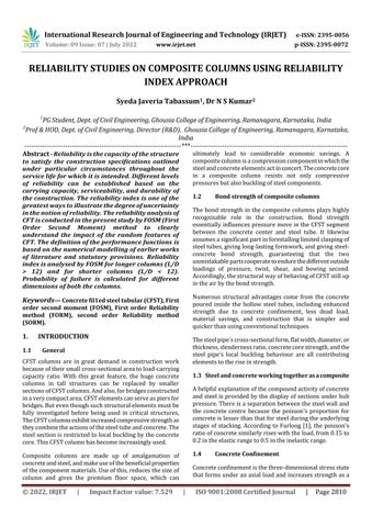
Sinceitisexpectedthatboththeresistanceprovidedbya system "R" and the load measurements on the system "S" vary,M=R Swillalsoshowfluctuation.Thedependability index‘β’isknownastheratiobetweenthemeanvalueofthe M function (µM) and the standard deviation of the M function(σM).If‘M’hasanormaldistributionandif‘Φ’is the cumulative distribution function, then β = Φ(1 Reliability)=µM/σM.
TheMostProbablePoint(MPP)isalsoknownasthepointon thelimitstatethatisfurthestfromtheorigininconventional normalspace.
Pf=Φ( β) (1.1) yieldsthefirst orderreliability estimate.
Where ‘Φ’ is the standard normal variable's cumulative distributionfunctionand‘β’isthedistancefromtheoriginto MPP.Differentmethodscanbeusedtodeterminethemost likely point (MPP). Figure 3.1 makes it obvious that the estimatedMPPsfallwithinthetargetreliabilityrange.
Fig:3.1mostprobablepointoffailure
Despitetheuncertaintiesinthemanyfactorsemployedin thestudyanddesignofthestructure,itisvery difficultto calculate the absolute safety of the structure using deterministicanalysis.Therefore,oneofthemostimportant approachestoofferajustificationforasafetyrequirement forabuildingistoevaluateitsdependabilityorlikelihoodof failure. A popular definition of reliability is the possibility thatastructurewillcontinuetoserveitsoriginalpurpose. Failureofastructureisagenerictermthatdoesn'talways mean major failure, but rather that the structure doesn't work as intended, the possibility of failure is used as a measurable indicator of safety factor in calculations involvingstructuralreliability.
Various uncertainties plague the design process in civil engineering. Some of their hidden traits can be easily distinguished, while others cannot. Stochastic and uncertaintyinimplementingsystemsanditscomponentsare twocategoriesofuncertaintyincivilengineering.Thefirst group is probabilistic, but the other group depends on humanunderstandingofthebehaviouroftheentiresystem anditsconstituentparts.Thefivegroupsthatmakeupthe mostsignificantsourceofuncertaintiesincivilengineering areasfollows.
International Research Journal of Engineering and Technology (IRJET) e ISSN: 2395 0056
Volume: 09 Issue: 07 | July 2022 www.irjet.net p ISSN: 2395 0072
Thereliabilitytechnique,accordingtoJCSS,canbedivided intothreecategories.Allsemi probabilisticmethods,suchas the semi probabilistic safety concept, are summarised at level 1. The idea is the methodological underpinning of structuralengineeringstandardsandnorms.Toensurethe necessarylevelofreliability,itmakesuseofpartof safety considerations and characteristics of materials and operations.Therecanbenodistributionfunctionsutilised, andlevel1isexpectedtouselinearlimitstatefunctions.1st and2ndorderreliabilitytheories(FORM/SORM)establish level2technique.Thetechniquesareappliedtolevel1code calibration. Probabilistic techniques including numerical integration,stochasticsimulation,MonteCarlo,andothers areincludedatlevel3.Themethodsareemployedtoratethe level1andlevel2models.Fordirectstructuralstudies,level 2andlevel3methodscanbeutilised,althoughduetotheir complexity, they are rarely used. When conventional approachescannotgive the analyses,or whenthecurrent margin of safety need to be precisely calculated, the applicationofthemethodologiesmakessense.
Thepointstate"g(X)=0"isoftentimeslinearizedbymeansof theTaylorseriesdevelopment.Inthisstrategy,constancyis assessed utilizing the 1st or 2nd request Taylor series development.TheFirstOrderSecondMoment(FOSM)and Second Order Second Moment (SOSM) approaches, individually,arethenamesoftheseprocedures.
Reliability and probability of failure are calculatedbyFOSM(FirstOrderSecondMoment)method forlongerandshortercolumnsbytakingL/Dratioas:
Longercolumns, L/D>12 Shortercolumns, L/D<12 AccordingtoEurocode 4
Limitstatefunctionis G(θExE,θRxR)=θRxR θExE
Where E Randomvariablesforactioneffects.
R Random variables for resistance of structural member.
Designbucklingresistanceofcompositecolumn Rd=k{(AsFy/γm)+(0.875AcFck/γc)}
As Areaofsteeltube, Ac areaofconcrete, Fy yieldstrengthofsteel, Fck compressivestrengthofconcrete, γm&γc partialsafetyfactor,
Table: Statistical parameters of random variables
CategoryOf Variables Variables Distribution Mean Value µx
ActionEffect Factor(Θe)
Model Uncertainty
Standard Deviation Σx
Normal 1 0.10
C/SArea(A) Normal µa 0.02µa Yield Strength (Fy)
Resistance FactorFor CFT(Θr)
Log Normal Fy+2 Σx
Log Normal Fck+2 Σx
5
30 Compressive Strength (Fck)
Normal 1.10 0.14µq
Actions Permanent (G) Normal GK 0.1µg
4.1 Reliability Analysis by Using First Order Second Moment (FOSM) Method
Data:
Outerdiaofthetube = 33.7 mm
Thickness = 2.9 mm
Innerdiaofthetube = 30.8 mm
Length = 300 mm
Fck = 23.93 N/mm^
Fy = 310 N/mm^
Pcr = 123000 N
ɣm = 1.15
ɣc = 1.5
AreaofSteel(As) = 146.83425 mm^2
AreaofConcrete(Ac) = 744.6824 mm^2
AccordingtoEurocode, Performancefunctionis, M=R S
International Research Journal of Engineering and Technology (IRJET) e ISSN: 2395 0056
M=marginofsafety R=capacityofcolumn S=Demand M=θR((AsxFy/ɣm)+(0.85*Ac*Fck/ɣc)) θE*Pcr
Where: As/ɣm = 127.6819565 0.85*Ac/ɣc= 421.9866933
θR=ResistancefactorforCFST
θΕ=Actioneffectfactor
Consider:
θR=x1 Fy=x2 Fck=x3 θE=x4 M=(As/ɣm)*x1*x2+(0.85*Ac/ɣc)*x1*x3 x4*Pcr
μm= 57107.88282 σR = 19688.52151
ReliabilityIndex(β) =μm/σR= 2.900567358
ProbabilityofFailure, FromZTable for 0% Pf=0.187%
Furtherresultsaretabulatedforlongercolumns(L/D>12) and shorter columns (L/D<12). Graphs are ploted accordingly.
Table:ReliabilityIndexbyFOSMMethod LongerColumns (L/D>12)
SL no Diameter mm Thickness mm Lengthmm Reliability Index by FOSM (First Order Second Moment Method)
1 33.7 2.6 300 1.24
2 33.7 2.6 300 1.5
3 33.7 2.6 300 1.43
4 33.7 3.2 300 1.23
5 33.7 3.2 300 1.23
6 33.7 3.2 300 1.16
7 33.7 4 300 1.2
8 33.7 4 300 1.25
9 33.7 4 300 1.21
10 42.4 2.6 300 1.29
11 42.4 2.6 300 1.39 12 42.4 2.6 300 1.29
13 42.4 3.2 300 1.12
14 42.4 3.2 300 1.18
15 42.4 3.2 300 1.11
16 42.4 4 300 1.04
17 42.4 4 300 1.12
18 42.4 4 300 1.06
19 48.3 2.6 300 1.24
20 48.3 2.6 300 1.29
21 48.3 2.6 300 1.18
22 48.3 3.2 300 0.95 23 48.3 3.2 300 0.96 24 48.3 3.2 300 0.91 25 48.3 4 300 0.83 26 48.3 4 300 0.86
27 48.3 4 300 0.83
Table:Reliability LongerColumns(L/D>12)
1 337 26 300 089251 8925
2 337 26 300 093319 9332
3 337 26 300 092364 9236
4 337 32 300 089065 8907 5 337 32 300 089065 8907 6 337 32 300 085543 8554
7 33.7 4 300 0.88493 88.49 8 33.7 4 300 0.89435 89.44 9 337 4 300 088686 8869
10 424 26 300 090147 9015 11 424 26 300 091774 9177 12 424 26 300 090147 9015 13 424 32 300 086864 8686 14 424 32 300 0881 8810 15 424 32 300 08665 8665 16 42.4 4 300 0.85083 85.08 17 424 4 300 086864 8686 18 424 4 300 085543 8554 19 483 26 300 089251 8925 20 483 26 300 090147 9015 21 483 26 300 0881 8810 22 483 32 300 082894 8289 23 483 32 300 083147 8315 24 48.3 3.2 300 0.81859 81.86 25 483 4 300 079673 7967 26 483 4 300 080511 8051 27 483 4 300 079673 7967
Volume: 09 Issue: 07 | July 2022 www.irjet.net p ISSN: 2395 0072 © 2022, IRJET | Impact Factor value: 7.529 | ISO 9001:2008 Certified Journal | Page2813
International Research Journal of Engineering and Technology (IRJET) e ISSN: 2395 0056
Volume: 09 Issue: 07 | July 2022 www.irjet.net p ISSN: 2395 0072
Table:Reliability ShorterColumns(L/D<12)
Sl No Diamet ermm Thicknes smm Lengt hmm Reliabilit y Reliabilit yin%age
1 33.4 1.65 135 0.71904 71.904
2 33.4 2.11 201 0.76424 76.424
3 33.4 2.77 268 0.76424 76.424
4 33.4 1.65 135 0.7673 76.73
5 33.4 2.11 201 0.7673 76.73
6 33.4 2.77 268 0.76424 76.424
7 33.4 1.65 135 0.77035 77.035
8 33.4 2.11 201 0.77035 77.035
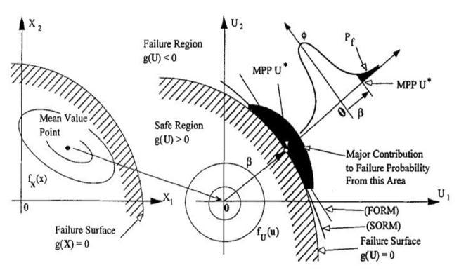
Graph: Variation of Reliability Longer Columns (L/D > 12)
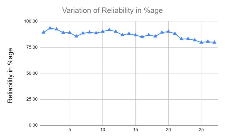
Table:ReliabilityIndexbyFOSMmethod ShorterColumns (L/D<12)
Sl No Diameter mm Thickness mm Length mm ReliabilityIndexby FOSM (First Order Second Moment Method)
1 33.4 1.65 135 0.58
2 33.4 2.11 201 0.72
3 33.4 2.77 268 0.72
4 33.4 1.65 135 0.73
5 33.4 2.11 201 0.73
6 33.4 2.77 268 0.72
7 33.4 1.65 135 0.74
8 33.4 2.11 201 0.74
9 33.4 2.77 268 0.73
10 42.2 1.65 170 0.74
11 42.2 2.11 254 0.74
12 42.2 2.77 338 0.73
13 42.2 1.65 170 0.75
14 42.2 2.11 254 0.74
15 42.2 2.77 338 0.74
16 42.2 1.65 170 0.76
17 42.2 2.11 254 0.75
18 42.2 2.77 338 0.74
19 48.3 1.65 194 0.75
20 48.3 2.11 290 0.74
21 48.3 2.77 387 0.73
22 48.3 1.65 194 0.77
23 48.3 2.11 290 0.75
24 48.3 2.77 387 0.74
25 48.3 1.65 194 0.78
26 48.3 2.11 290 0.76
27 48.3 2.77 387 0.75
9 33.4 2.77 268 0.7673 76.73
10 42.2 1.65 170 0.77035 77.035
11 42.2 2.11 254 0.77035 77.035
12 42.2 2.77 338 0.7673 76.73
13 42.2 1.65 170 0.77337 77.337
14 42.2 2.11 254 0.77035 77.035
15 42.2 2.77 338 0.77035 77.035
16 42.2 1.65 170 0.77637 77.637
17 42.2 2.11 254 0.77337 77.337
18 42.2 2.77 338 0.77035 77.035
19 48.3 1.65 194 0.77337 77.337
20 48.3 2.11 290 0.77035 77.035
21 48.3 2.77 387 0.7673 76.73
22 48.3 1.65 194 0.77935 77.935
23 48.3 2.11 290 0.77337 77.337
24 48.3 2.77 387 0.77035 77.035
25 48.3 1.65 194 0.7823 78.23
26 48.3 2.11 290 0.77637 77.637
27 48.3 2.77 387 0.77337 77.337
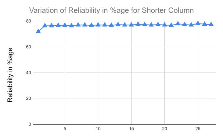
Graph: Variation of Reliability Shorter Columns (L/D < 12)
The difference between the analytical and codal results for longer and shorter CFT columns demonstratesthesuitabilityofthedesign.
2022, IRJET | Impact Factor value: 7.529 | ISO 9001:2008 Certified Journal
International Research Journal of Engineering and Technology (IRJET) e ISSN: 2395 0056
TheCFT columnsarestrong enoughto withstand theimposedloads,andexperimentalandanalytical findingswillbeconsistent.
Reliability Index analysed by FOSM method for longer columns increases as increase in diameter and thickness of column, whereas, for shorter columnsremainsalmostconstant.
Whenthesteeltube'sthicknessisincreasedwhile other factors such as concrete grade, steel grade, length, and diameter remain constant, the probabilitythattheCFTcolumnwillfailincreases.
TheprobabilityoftheCFTcolumnfailingdecreases as concrete quality in the steel tube increases, keepingotherfactorssuchaslength,diameter,and thicknessunchanged.
TheprobabilityoftheCFTcolumnfailingincreases withanincreaseinsteeltubediameteratconstant concretegrade,steelgrade,length,andthickness.
[1]Furlong,R.W.,1967,“StrengthofSteel encasedConcrete Beam columns,” J. Structural Engineering; ASCE, 93(5), pp.113 124.
[2]Schneider,S.,1998,“AxiallyLoadedConcreteFilledSteel tubes,”ASCE, J. Structural Engineering., 124(10), pp.1125 1138.
[3]Shanmugam,N.E.,andLakshmi,2001,“StateoftheArt report on Steel Concrete Composite Columns,” J. of ConstructionalSteelResearch.,57(1),pp.1041 1080.
[4] Prion, HGL, and Boehme, J., 1989, “Beam column BehaviourofSteeltubesFilledwithHigh strengthconcrete,” Proc.FourthInternationalColloquium,SSRC,NewYork.,pp. 439 449.
[5] O’Shea, M. D., and Bridge, R. Q., 1995, “Circular Thin Walled Concrete filled Steel tubes,” Proc. PCSSC 95, 4th Pacific Structural Steel Conference, Steel Concrete CompositeStructures.,3,pp.53 60.
[6]MilanHolicky&JanaMarkova“calibrationofreliability elementsforacolumns”JCSSworkshoponreliabilitybased codecalibration.
[7]EC4:1994,Eurocode4: Design ofCompositeSteel and Concrete structures, European Committee for Standardization,Brussels,Belgium
[8] AISC: 2005, Load and Resistance Factor Design SpecificationforStructuralSteelBuilding,AmericanInstitute ofSteelConstruction,Chicago.
[9] AISC LRFD: 1999, Load and Resistance Factor Design SpecificationforStructuralSteelBuilding,AmericanInstitute ofSteelConstruction,Chicago.
[10] ACI318: 1999, Building Code Requirements For Structural Concrete and Commentary, American Concrete Institute,FarmingtonHills,Mich.
[11] AS3600: 1994, Australian Standards for Reinforced ConcreteStructures,StandardsAustralia,Sydney.
[12]AS4100:1998,AustralianStandardsforSteelstructures, StandardsAustralia,Sydney.
[13]Surya J.Varma and JaneH.Henderson“Studyonthe Bond Strength of Steel Concrete CompositeRectangular FlutedSections”https://doi.org/10.1155/2020/8844799.
[14] Chethan Kumar S, Khalid Nayaz Khan and N.S.Kumar “RELIABILITYSTUDYOFCONCRETEFILLEDTUBESUSING RELIABILITY INDEX APPROACH” International Journal of AdvancesinMechanicalandCivilEngineering,ISSN:2394 2827
[15]ZhongTao,Tian YiSong,BrianUy,Lin HaiHan“Bond behaviour in concrete filled steel tubes” Journal ofConstructional Steel Research, 120, 81 93.https://doi.org/10.1016/j.jcsr.2015.12.030
[16]IzabelaSkrzypczaka,MartaSáowikb,LidiaBuda OĪóga “The application of reliability analysis in engineering practice reinforced concrete foundation” Procedia Engineering193(2017)144 151
[17] Wan Qing Lyu, Lin Hai Han “Investigation on bond strength between recycled aggregate concrete(RAC) and steeltubeinRAC filledsteeltubes”JournalofConstructional SteelResearch155(2019)438 459
[18] Anusha T S, Dr.N.S.Kumar “Optimization of Bond strength in CFST Columnsusing GRA (GreyRelational Analysis)”2021IJCRT|Volume9,Issue7July2021|ISSN: 2320 2882
[19] MilovanStanojev, DragoslavStojić “RELIABILITY ANALYSISOFSTRUCTURES”Series:ArchitectureandCivil Engineering Vol. 12, No3, 2014, pp. 265 272DOI: 10.2298/FUACE1403265S
[20] Shivadarshan S, Chethan Kumar S, Dr. N. S. Kumar “Experimental Investigation on Bond Strength in Self CompactingConcreteFilledSteelTube”ImpactFactorvalue: 7.211|ISO9001:2008CertifiedJournal|
[21] AbubakarIdris and Mohammed UsmanAttah 2007 “ReliabilityInvestigationofSteelCasedColumns”Australian JournalofBasicandAppliedSciences,1(4):561 570,2007 ISSN1991 8178.
Volume: 09 Issue: 07 | July 2022 www.irjet.net p ISSN: 2395 0072 © 2022, IRJET | Impact Factor value: 7.529 | ISO 9001:2008 Certified Journal | Page2815
[22] Arvind Kumar Mishra “Role of Reliability Analysis in StructuralDesign” HYDRONEPAL|ISSUENO.24|JANUARY 2019
[23] M. Tomii, K. Yoshimura, Y. Morishita, A method of improvingbondstrengthbetweensteeltubeandconcrete corecastincircularsteeltubularcolumns,Transactionsof theJapanConcreteInstitute,vol.2,1980,pp.319 326.
[24] M. Tomii, K. Yoshimura, Y. Morishita, A method of improvingbondstrengthinbetweensteeltubeandconcrete core cast in square and octagonal steel tubular columns, TransactionsoftheJapanConcreteInstitute,vol.2,1980,pp. 327 334.
[25]K.S.Virdi,P.J.Dowling,Bondstrengthinconcretefilled steeltubes,IABSEProceedings,vol.80,1980,pp.125 139, P 33.
[26] H. Shakir Khalil, Push out strength of concrete filled steelhollowsections,Struct.Eng.71(1993)230 243.
International Research Journal of Engineering and Technology (IRJET) e ISSN: 2395 0056 Volume: 09 Issue: 07 | July 2022 www.irjet.net p ISSN: 2395 0072 © 2022, IRJET | Impact Factor value: 7.529 | ISO 9001:2008 Certified Journal |