International Research Journal of Engineering and Technology (IRJET)
e-ISSN: 2395-0056
Volume: 09 Issue: 07 | July 2022
p-ISSN: 2395-0072
www.irjet.net
Mutual coupling analysis for 2*2 MIMO antenna using DGS Anand1 and Vijaya K2 1M.
Tech Scholar, Dept of ECE, BMSCE, Bengaluru, Karnataka, India Dept. of ECE, BMSCE, Bengaluru, Karnataka, India ---------------------------------------------------------------------***--------------------------------------------------------------------hybrid techniques [6]. In this paper, we used DGS (defective Abstract - Mutual coupling significantly lowers MIMO 2Professor,
(multiple input multiple output) antennas' system performance and radiation patterns. In this paper, mutual coupling analysis of two element MIMO antenna operating at 28 GHz with various spacing between them is carried out. The analysis was done with and without applying DGS to the proposed structure. The spacing of λ/2, λ/4 and λ/8 is considered between the antenna elements for mutual coupling analysis, where λ is the wavelength at frequency of 28GHz. It has been found that mutual coupling is greater when there is less space between the two antenna components, i.e., the mutual coupling obtained is greater when the spacing between the antenna elements is λ /8 in both the presence and absence of DGS. All the simulations carried out in this work has been done on HFSS v.15.0 tool.
ground structure) because it is easier to design, and cost required for designing purpose also less compared to other methods.
Key Words: MIMO Antenna, Mutual Coupling, DGS, Inter
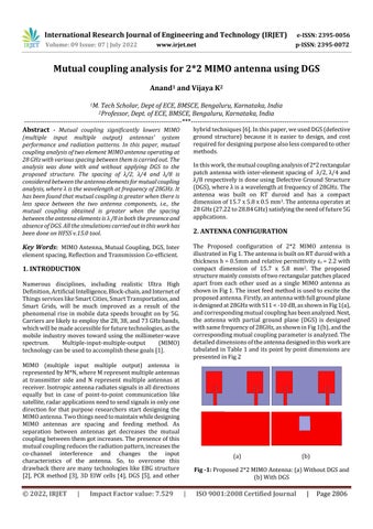
The Proposed configuration of 2*2 MIMO antenna is illustrated in Fig 1. The antenna is built on RT duroid with a thickness h = 0.5mm and relative permittivity ɛr = 2.2 with compact dimension of 15.7 x 5.8 mm2. The proposed structure mainly consists of two rectangular patches placed apart from each other used as a single MIMO antenna as shown in Fig 1. The inset feed method is used to excite the proposed antenna. Firstly, an antenna with full ground plane is designed at 28GHz with S11 < -10 dB, as shown in Fig 1(a), and corresponding mutual coupling has been analyzed. Next, the antenna with partial ground plane (DGS) is designed with same frequency of 28GHz, as shown in Fig 1(b), and the corresponding mutual coupling parameter is analyzed. The detailed dimensions of the antenna designed in this work are tabulated in Table 1 and its point by point dimensions are presented in Fig 2
In this work, the mutual coupling analysis of 2*2 rectangular patch antenna with inter-element spacing of λ/2, λ/4 and λ/8 respectively is done using Defective Ground Structure (DGS), where λ is a wavelength at frequency of 28GHz. The antenna was built on RT duroid and has a compact dimension of 15.7 x 5.8 x 0.5 mm3. The antenna operates at 28 GHz (27.22 to 28.84 GHz) satisfying the need of future 5G applications.
2. ANTENNA CONFIGURATION
element spacing, Reflection and Transmission Co-efficient.
1. INTRODUCTION Numerous disciplines, including realistic Ultra High Definition, Artificial Intelligence, Block-chain, and Internet of Things services like Smart Cities, Smart Transportation, and Smart Grids, will be much improved as a result of the phenomenal rise in mobile data speeds brought on by 5G. Carriers are likely to employ the 28, 38, and 73 GHz bands, which will be made accessible for future technologies, as the mobile industry moves toward using the millimeter-wave spectrum. Multiple-input-multiple-output (MIMO) technology can be used to accomplish these goals [1]. MIMO (multiple input multiple output) antenna is represented by M*N, where M represent multiple antennas at transmitter side and N represent multiple antennas at receiver. Isotropic antenna radiates signals in all directions equally but in case of point-to-point communication like satellite, radar applications need to send signals in only one direction for that purpose researchers start designing the MIMO antenna. Two things need to maintain while designing MIMO antennas are spacing and feeding method. As separation between antennas get decreases the mutual coupling between them got increases. The presence of this mutual coupling reduces the radiation pattern, increases the co-channel interference and changes the input characteristics of the antenna. So, to overcome this drawback there are many technologies like EBG structure [2], PCR method [3], 3D EIW cells [4], DGS [5], and other
© 2022, IRJET
|
Impact Factor value: 7.529
(a)
(b)
Fig -1: Proposed 2*2 MIMO Antenna: (a) Without DGS and (b) With DGS
|
ISO 9001:2008 Certified Journal
|
Page 2806